EP0958873A1 - Plaquette de rainurage - Google Patents
Plaquette de rainurage Download PDFInfo
- Publication number
- EP0958873A1 EP0958873A1 EP99109900A EP99109900A EP0958873A1 EP 0958873 A1 EP0958873 A1 EP 0958873A1 EP 99109900 A EP99109900 A EP 99109900A EP 99109900 A EP99109900 A EP 99109900A EP 0958873 A1 EP0958873 A1 EP 0958873A1
- Authority
- EP
- European Patent Office
- Prior art keywords
- edge
- radius
- cutting
- curvature
- cutting insert
- Prior art date
- Legal status (The legal status is an assumption and is not a legal conclusion. Google has not performed a legal analysis and makes no representation as to the accuracy of the status listed.)
- Granted
Links
- 238000007792 addition Methods 0.000 description 1
- 230000015572 biosynthetic process Effects 0.000 description 1
- 238000012217 deletion Methods 0.000 description 1
- 230000037430 deletion Effects 0.000 description 1
- 230000000694 effects Effects 0.000 description 1
- 230000002349 favourable effect Effects 0.000 description 1
- 238000003754 machining Methods 0.000 description 1
- 238000004519 manufacturing process Methods 0.000 description 1
- 238000012986 modification Methods 0.000 description 1
- 230000004048 modification Effects 0.000 description 1
- 238000006467 substitution reaction Methods 0.000 description 1
- 230000003746 surface roughness Effects 0.000 description 1
Images
Classifications
-
- B—PERFORMING OPERATIONS; TRANSPORTING
- B23—MACHINE TOOLS; METAL-WORKING NOT OTHERWISE PROVIDED FOR
- B23B—TURNING; BORING
- B23B27/00—Tools for turning or boring machines; Tools of a similar kind in general; Accessories therefor
- B23B27/04—Cutting-off tools
-
- B—PERFORMING OPERATIONS; TRANSPORTING
- B23—MACHINE TOOLS; METAL-WORKING NOT OTHERWISE PROVIDED FOR
- B23B—TURNING; BORING
- B23B27/00—Tools for turning or boring machines; Tools of a similar kind in general; Accessories therefor
- B23B27/04—Cutting-off tools
- B23B27/045—Cutting-off tools with chip-breaking arrangements
-
- Y—GENERAL TAGGING OF NEW TECHNOLOGICAL DEVELOPMENTS; GENERAL TAGGING OF CROSS-SECTIONAL TECHNOLOGIES SPANNING OVER SEVERAL SECTIONS OF THE IPC; TECHNICAL SUBJECTS COVERED BY FORMER USPC CROSS-REFERENCE ART COLLECTIONS [XRACs] AND DIGESTS
- Y10—TECHNICAL SUBJECTS COVERED BY FORMER USPC
- Y10T—TECHNICAL SUBJECTS COVERED BY FORMER US CLASSIFICATION
- Y10T407/00—Cutters, for shaping
- Y10T407/23—Cutters, for shaping including tool having plural alternatively usable cutting edges
- Y10T407/235—Cutters, for shaping including tool having plural alternatively usable cutting edges with integral chip breaker, guide or deflector
-
- Y—GENERAL TAGGING OF NEW TECHNOLOGICAL DEVELOPMENTS; GENERAL TAGGING OF CROSS-SECTIONAL TECHNOLOGIES SPANNING OVER SEVERAL SECTIONS OF THE IPC; TECHNICAL SUBJECTS COVERED BY FORMER USPC CROSS-REFERENCE ART COLLECTIONS [XRACs] AND DIGESTS
- Y10—TECHNICAL SUBJECTS COVERED BY FORMER USPC
- Y10T—TECHNICAL SUBJECTS COVERED BY FORMER US CLASSIFICATION
- Y10T407/00—Cutters, for shaping
- Y10T407/24—Cutters, for shaping with chip breaker, guide or deflector
- Y10T407/245—Cutters, for shaping with chip breaker, guide or deflector comprising concave surface in cutting face of tool
-
- Y—GENERAL TAGGING OF NEW TECHNOLOGICAL DEVELOPMENTS; GENERAL TAGGING OF CROSS-SECTIONAL TECHNOLOGIES SPANNING OVER SEVERAL SECTIONS OF THE IPC; TECHNICAL SUBJECTS COVERED BY FORMER USPC CROSS-REFERENCE ART COLLECTIONS [XRACs] AND DIGESTS
- Y10—TECHNICAL SUBJECTS COVERED BY FORMER USPC
- Y10T—TECHNICAL SUBJECTS COVERED BY FORMER US CLASSIFICATION
- Y10T407/00—Cutters, for shaping
- Y10T407/25—Cutters, for shaping including cut off tool
Definitions
- the present invention relates to a cutting insert for grooving operations.
- the present cutting insert according to the invention is suitable for radial grooving, although it also can be used for various axial grooving and parting off operations, as well as for axial and radial longitudinal turning operations.
- Chip breaking and chip formation are often of decisive importance for undisturbed production.
- Modern high productive machines put very high claims on good chip transport. Long uncontrollable chips can easily cause machine interruptions and cessation. Chip control must therefore be given high priority and governs to a high degree the tool design.
- Cutting inserts intended for grooving operations and parting off are usually clamped in a holder, which is blade shaped in order to be useful in the slot produced.
- the expression "holder of blade type” is also intended to comprise slot mills.
- Such cutting inserts are for example known from US-A-4,778,311, US-A-4,992,008, US-A-5,135,336 and US-A-5,423,639.
- a first purpose is to produce a cutting insert, which is well suited to give improved finish of the surfaces in the slot produced in a work piece.
- a metalcutting insert comprising a shank portion and a cutting head.
- the shank portion defines a longitudinal axis
- the cutting head is located at a longitudinal end of the shank portion.
- the cutting head includes an upper surface, a bottom surface, two side clearance surfaces each extending between the upper and bottom surfaces, and a front clearance surface disposed between the side clearance surfaces and extending between the upper and bottom surfaces.
- An intersection between the upper surface and the front clearance surface forms a main cutting edge extending generally perpendicular to the longitudinal axis.
- the intersection between the upper surface and each side clearance surface defines a side edge having a clearance angle.
- the upper surface includes a pair of ridges extending generally longitudinally on opposite sides of the longitudinal axis and spaced apart to define a chip-forming recess between one another.
- the cutting insert further includes corner cutting edges extending between respective ones of the side edges and the main cutting edge.
- Each corner cutting edge includes a primary curved edge extending from the main cutting edge, and a curved wiper edge extending from the primary curved edge to the side edge.
- the primary curved edge has a smaller radius of curvature than the curved wiper edge.
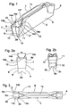
- Figures 1-3 shows a cutting insert for grooving according to the invention including a body of parallelepipedic shape with an upper surface 1, a bottom surface 2, a forward end surface 3, a rear end surface 4, as well as opposite plane parallel side faces 5, 6.
- the cutting insert is generally made of coated or sometimes non-coated cemented carbide; the upper surface 1 and the bottom surface 2 are each shaped with a longitudinally concave V-shaped keyway Ia and 2a.
- the cuffing insert can be as the embodiment according in figure 2b, where the bottom support surfaces 2b, 2c on respective sides of the central concave groove 2a, have an inclination and are intended to support against corresponding inclined support surfaces in a blade holder in the way that is described in Swedish Patent Application No.
- the central part of the cutting insert is a shank portion defining a longitudinal axis.
- a cutting head is formed at each longitudinal end of the shank portion.
- Each cutting head has an end surface composed of a front clearance surface 7 that by the intersection with the upper surface 1 forms a transverse cutting edge 8a, which via a corner 15, 16 extends to side edges 8b.
- the clearance surface 7 intersects, via a transverse break line 9, a lower front surface 10, which extends essentially perpendicularly toward the bottom surface 2.
- Each of the cutting heads has two side clearance surfaces 11, 12, situated laterally outwardly with respect to the longitudinal axis, and which via a break line 13 merge into respective ones of the side surfaces 5.
- the upper surface disposed adjacent the cutting edge 8 is a chip surface that extends inwards from the cutting edge 8 and is formed with a chip former 14 in the shape of a recess that intersects the cutting edge and passes between two separate ridges 20 and 21.
- the cutting edge 8 becomes concave in relation to the upper surface 1 and is formed with a chip angle which varies along the cuffing edge of the insert such that the chip angle is more positive at the central portion 8a than at the end portions 8c and 8d of the main cuffing edge. That is, the chip angle formed between the clearance surface 7 and a central recess 14a of the chip former, is smaller than chip angles formed between the clearance surface 7 and the ridges 20, 21.
- the depth of the recess 14a first increases from the cutting edge and, at some distance from said cutting edge 8, begins to diminish.
- the angle ⁇ extends uniformly in the axial direction, in a direction away from the cutting edge 8.
- the design is such that the obliquely downwards inclined inner side faces 14b and 14c of the ridges 20 and 21 have a width that diminishes uniformly from a broad area neat the cutting edge to a minimum area at the level of raised portions 14d, 14e which lie above the cutting edge 8.
- the width of the inner side faces 14b, 14c remains essentially constant in a rearward direction after passing the portions 14d and 14e.
- the side faces 14b and 14c have portions which converge rearwardly into a concave shaped end portion 14f.
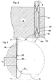
- figure 4-5 there is shown a cutting insert according to figure 1-3 in engagement with a work piece A.
- Each corner portion on the upper side 1 of the insert includes a varying convex radius of curvature. That is, each corner includes a primary curved edge 15, which extends to the adjacent end portion 8c of the main cutting edge 8, as well as a secondary cutting edge 16 or "wiper edge.” In order to reinforce the cutting edge, this wiper edge 16 could possibly be equipped with a primary chamfer. As shown in figure 5 the wiper edge 16 is formed with a radius R2 that is substantially bigger than the radius R1 of primary edge 15, whereby the edge 16 appears almost straight in Fig. 5. Wiper edge 16 extends rearwardly to the side edge 8b, the radius R3 of which is substantially less than R2. The curved edge 8b extends rearwardly with a side clearance angle of about 1-5° preferably 2-3°.
- Radius R2 of the wiper edge 16 is chosen such that the edge 16 acts like a round insert.
- the wiper edge can consequently be considered as being analogous to a segment of an imaginary circular round insert.
- the substantial advantage of the present insert compared with a round insert is that the primary edge 15 and the wiper edge 16 generate considerably narrower and thicker chips than compared with a round insert under the same operation parameters, which gives good chip control. Since radius R2 is chosen considerably larger than R1, a favorable "wiper" effect is obtained which gives considerably improved surface finish. As a further consequence, a subsequent finishing operation can be eliminated.
- the different radii of the various curved edges should be chosen within the following intervals:
Landscapes
- Engineering & Computer Science (AREA)
- Mechanical Engineering (AREA)
- Cutting Tools, Boring Holders, And Turrets (AREA)
- Milling Processes (AREA)
- Drilling Tools (AREA)
- Perforating, Stamping-Out Or Severing By Means Other Than Cutting (AREA)
- Drilling And Boring (AREA)
- Knives (AREA)
Applications Claiming Priority (2)
| Application Number | Priority Date | Filing Date | Title |
|---|---|---|---|
| SE9801800 | 1998-05-22 | ||
| SE9801800A SE512094C2 (sv) | 1998-05-22 | 1998-05-22 | Skär för spårstickning |
Publications (2)
| Publication Number | Publication Date |
|---|---|
| EP0958873A1 true EP0958873A1 (fr) | 1999-11-24 |
| EP0958873B1 EP0958873B1 (fr) | 2001-12-12 |
Family
ID=20411405
Family Applications (1)
| Application Number | Title | Priority Date | Filing Date |
|---|---|---|---|
| EP99109900A Expired - Lifetime EP0958873B1 (fr) | 1998-05-22 | 1999-05-20 | Plaquette de rainurage |
Country Status (12)
| Country | Link |
|---|---|
| US (1) | US6238147B1 (fr) |
| EP (1) | EP0958873B1 (fr) |
| JP (1) | JP3803549B2 (fr) |
| KR (1) | KR100614958B1 (fr) |
| CN (1) | CN1116140C (fr) |
| AT (1) | ATE210525T1 (fr) |
| AU (1) | AU745207B2 (fr) |
| CA (1) | CA2332285C (fr) |
| DE (1) | DE69900567T2 (fr) |
| ES (1) | ES2169578T3 (fr) |
| SE (1) | SE512094C2 (fr) |
| WO (1) | WO1999061187A1 (fr) |
Cited By (4)
| Publication number | Priority date | Publication date | Assignee | Title |
|---|---|---|---|---|
| DE10006303A1 (de) * | 2000-02-12 | 2001-08-23 | Kemmer Hartmetallwerkzeuge Gmb | Schneideinsatz, insbesondere Abstechschneideinsatz |
| SG96672A1 (en) * | 2000-12-28 | 2003-06-16 | Ngk Spark Plug Co | Cutting tool and indexiable insert therefor |
| WO2004035257A2 (fr) | 2002-10-18 | 2004-04-29 | Manchester Tool Company | Support d'outil et insert de coupe metallique a surfaces d'ebauche |
| EP3213843A4 (fr) * | 2014-10-28 | 2018-07-18 | NGK Spark Plug Co., Ltd. | Plaquette de coupe |
Families Citing this family (36)
| Publication number | Priority date | Publication date | Assignee | Title |
|---|---|---|---|---|
| SE519602C2 (sv) * | 1999-09-16 | 2003-03-18 | Sandvik Ab | Skär för spårsvarvningsoperationer med konkav central bottenyta |
| USD466537S1 (en) | 2000-03-02 | 2002-12-03 | Sandvik Ab | Cutting insert for chip forming machining |
| SE520629C2 (sv) * | 2000-09-05 | 2003-08-05 | Sandvik Ab | Skär för grovsvarvningsändamål med avsmalnande bakre ände |
| USD470516S1 (en) | 2001-08-31 | 2003-02-18 | Sandvik Aktiebolag (Publ) | Cutting insert |
| USD470517S1 (en) | 2001-08-31 | 2003-02-18 | Sandvik Aktiebolag (Publ) | Cutting insert |
| US6623217B2 (en) | 2001-09-24 | 2003-09-23 | Valenite, Inc. | Indexable turning insert |
| US6742971B2 (en) * | 2002-02-19 | 2004-06-01 | Manchester Tool Company | Cutting insert |
| AT6205U1 (de) * | 2002-06-21 | 2003-06-25 | Plansee Tizit Ag | Schneideinsatz mit zwei gegenüberliegenden schneidköpfen |
| USD502473S1 (en) * | 2003-04-04 | 2005-03-01 | Manchester Tool Company | Cutting insert structure |
| JP4407503B2 (ja) * | 2004-12-16 | 2010-02-03 | 三菱マテリアル株式会社 | 切削インサートのクランプ機構 |
| USD537854S1 (en) | 2004-12-29 | 2007-03-06 | Manchester Tool Company | Cutting insert |
| USD527400S1 (en) | 2004-12-29 | 2006-08-29 | Manchester Tool Company | Cutting insert |
| USD535312S1 (en) | 2004-12-29 | 2007-01-16 | Manchester Tool Company | Cutting insert |
| EP1980349A3 (fr) * | 2007-03-30 | 2009-02-11 | Mitsubishi Materials Corporation | Insert de découpe |
| US7665933B2 (en) * | 2007-03-30 | 2010-02-23 | Mitsubishi Materials Corporation | Cutting insert |
| KR20100014870A (ko) * | 2007-04-20 | 2010-02-11 | 미쓰비시 마테리알 가부시키가이샤 | 절삭 인서트 및 절삭 방법 |
| KR20080099471A (ko) * | 2007-05-09 | 2008-11-13 | 대구텍 주식회사 | 분단 및 모깍기 용 인서트 |
| SE0702232L (sv) * | 2007-10-05 | 2009-04-06 | Sandvik Intellectual Property | Skär för avstickning eller spårstickning och tillverkningssätt |
| CN101306476B (zh) * | 2008-06-30 | 2010-04-14 | 株洲钻石切削刀具股份有限公司 | 用于加工高粘性、耐高温金属材料的切削刀片 |
| JP5332503B2 (ja) * | 2008-10-27 | 2013-11-06 | 三菱マテリアル株式会社 | 切削インサート |
| JP5332504B2 (ja) * | 2008-10-27 | 2013-11-06 | 三菱マテリアル株式会社 | 切削インサート |
| IL203014A (en) * | 2009-12-29 | 2013-03-24 | Iscar Ltd | Cutting tool and cutting insert therefor |
| CN102712046B (zh) * | 2010-01-29 | 2014-05-21 | 京瓷株式会社 | 切削镶刀及切削工具、以及使用该切削工具的被切削件的切削方法 |
| JP5698833B2 (ja) * | 2011-02-28 | 2015-04-08 | 京セラ株式会社 | 切削インサートおよび切削工具、並びにそれらを用いた切削加工物の製造方法 |
| WO2015146956A1 (fr) * | 2014-03-25 | 2015-10-01 | 京セラ株式会社 | Plaquette de coupe, outil de coupe et procédé de fabrication de produit coupé |
| EP3023178B1 (fr) * | 2014-11-24 | 2022-05-11 | Sandvik Intellectual Property AB | Procédé de meulage d'un insert de rainurage/séparation et insert de rainurage/séparation |
| USD824438S1 (en) * | 2015-12-29 | 2018-07-31 | Korloy Inc. | Grooving insert for a machine tool |
| JP6798663B2 (ja) * | 2016-04-27 | 2020-12-09 | 住友電工ハードメタル株式会社 | 切削インサート |
| PT3720635T (pt) * | 2017-12-04 | 2023-08-24 | Iscar Ltd | Pastilha de sangria para operações de largura estreita |
| USD953395S1 (en) * | 2020-05-15 | 2022-05-31 | Korloy Inc. | Grooving insert |
| CN115666827B (zh) * | 2020-05-21 | 2026-03-20 | 京瓷株式会社 | 切削刀片、切削刀具及切削加工物的制造方法 |
| USD953396S1 (en) * | 2021-04-29 | 2022-05-31 | Korloy Inc. | Grooving insert for machine tools for metalworking |
| US12465981B2 (en) * | 2022-09-07 | 2025-11-11 | Iscar, Ltd. | Cemented carbide cutting insert for parting metal workpieces |
| CN116000378B (zh) * | 2022-12-28 | 2026-03-24 | 厦门金鹭特种合金有限公司 | 一种切削刀片及切削刀具 |
| USD1086243S1 (en) * | 2023-12-08 | 2025-07-29 | Korloy Inc. | Cutting insert for machine tools for metalworking |
| USD1109200S1 (en) * | 2024-02-20 | 2026-01-13 | Korloy Inc. | Grooving insert for machine tools for metalworking |
Citations (2)
| Publication number | Priority date | Publication date | Assignee | Title |
|---|---|---|---|---|
| US4992008A (en) * | 1987-10-02 | 1991-02-12 | Iscar Ltd. | Cutting insert |
| WO1995000272A1 (fr) * | 1993-06-25 | 1995-01-05 | Kennametal Inc. | Geometrie du point d'attaque d'un outil de tournage pour avoir une surface a rugosite amelioree |
Family Cites Families (9)
| Publication number | Priority date | Publication date | Assignee | Title |
|---|---|---|---|---|
| US2725334A (en) * | 1951-11-20 | 1955-11-29 | American Cholesterol Products | Modified lanolin |
| SE452273B (sv) | 1986-05-07 | 1987-11-23 | Seco Tools Ab | Sker for avstickning |
| SU1521529A1 (ru) * | 1986-12-02 | 1989-11-15 | Предприятие П/Я А-3985 | Зуб режущего инструмента |
| DE3907922A1 (de) * | 1989-03-11 | 1990-04-26 | Zinner Gmbh Praezisionswerkzeu | Spanendes werkzeug |
| JP2519801B2 (ja) * | 1989-07-18 | 1996-07-31 | 住友電気工業株式会社 | 突切り用工具 |
| DE9214563U1 (de) | 1992-10-28 | 1992-12-10 | Sandvik Ab, Sandviken | Schneideinsatz für die spanabhebende Bearbeitung von Werkstücken |
| US5725334A (en) * | 1993-03-29 | 1998-03-10 | Widia Gmbh | Cutting insert |
| SE509224C2 (sv) * | 1994-05-19 | 1998-12-21 | Sandvik Ab | Vändskär |
| SE9504174L (sv) * | 1995-11-23 | 1996-12-02 | Sandvik Ab | Skär för spårstickning samt breddning av spår |
-
1998
- 1998-05-22 SE SE9801800A patent/SE512094C2/sv unknown
-
1999
- 1999-05-20 AU AU46618/99A patent/AU745207B2/en not_active Ceased
- 1999-05-20 ES ES99109900T patent/ES2169578T3/es not_active Expired - Lifetime
- 1999-05-20 KR KR1020007013094A patent/KR100614958B1/ko not_active Expired - Lifetime
- 1999-05-20 JP JP2000550628A patent/JP3803549B2/ja not_active Expired - Lifetime
- 1999-05-20 WO PCT/SE1999/000860 patent/WO1999061187A1/fr not_active Ceased
- 1999-05-20 EP EP99109900A patent/EP0958873B1/fr not_active Expired - Lifetime
- 1999-05-20 AT AT99109900T patent/ATE210525T1/de active
- 1999-05-20 DE DE69900567T patent/DE69900567T2/de not_active Expired - Lifetime
- 1999-05-20 CA CA002332285A patent/CA2332285C/fr not_active Expired - Fee Related
- 1999-05-20 CN CN99806495A patent/CN1116140C/zh not_active Expired - Lifetime
- 1999-05-24 US US09/316,965 patent/US6238147B1/en not_active Expired - Lifetime
Patent Citations (2)
| Publication number | Priority date | Publication date | Assignee | Title |
|---|---|---|---|---|
| US4992008A (en) * | 1987-10-02 | 1991-02-12 | Iscar Ltd. | Cutting insert |
| WO1995000272A1 (fr) * | 1993-06-25 | 1995-01-05 | Kennametal Inc. | Geometrie du point d'attaque d'un outil de tournage pour avoir une surface a rugosite amelioree |
Cited By (7)
| Publication number | Priority date | Publication date | Assignee | Title |
|---|---|---|---|---|
| DE10006303A1 (de) * | 2000-02-12 | 2001-08-23 | Kemmer Hartmetallwerkzeuge Gmb | Schneideinsatz, insbesondere Abstechschneideinsatz |
| SG96672A1 (en) * | 2000-12-28 | 2003-06-16 | Ngk Spark Plug Co | Cutting tool and indexiable insert therefor |
| US6843620B2 (en) | 2000-12-28 | 2005-01-18 | Ngk Spark Plug Co., Ltd. | Cutting tool and indexiable insert therefor |
| WO2004035257A2 (fr) | 2002-10-18 | 2004-04-29 | Manchester Tool Company | Support d'outil et insert de coupe metallique a surfaces d'ebauche |
| EP1558431A4 (fr) * | 2002-10-18 | 2008-05-21 | Manchester Tool Co | Support d'outil et insert de coupe metallique a surfaces d'ebauche |
| US7883300B1 (en) | 2002-10-18 | 2011-02-08 | Kennametal Inc. | Tool holder and metal cutting insert with chip breaking surfaces |
| EP3213843A4 (fr) * | 2014-10-28 | 2018-07-18 | NGK Spark Plug Co., Ltd. | Plaquette de coupe |
Also Published As
| Publication number | Publication date |
|---|---|
| SE9801800L (sv) | 1999-11-23 |
| JP3803549B2 (ja) | 2006-08-02 |
| KR100614958B1 (ko) | 2006-08-25 |
| ES2169578T3 (es) | 2002-07-01 |
| AU745207B2 (en) | 2002-03-14 |
| DE69900567T2 (de) | 2002-08-01 |
| JP2002516185A (ja) | 2002-06-04 |
| CN1116140C (zh) | 2003-07-30 |
| CA2332285A1 (fr) | 1999-12-02 |
| EP0958873B1 (fr) | 2001-12-12 |
| SE9801800D0 (sv) | 1998-05-22 |
| WO1999061187A1 (fr) | 1999-12-02 |
| SE512094C2 (sv) | 2000-01-24 |
| ATE210525T1 (de) | 2001-12-15 |
| DE69900567D1 (de) | 2002-01-24 |
| KR20010025083A (ko) | 2001-03-26 |
| AU4661899A (en) | 1999-12-13 |
| US6238147B1 (en) | 2001-05-29 |
| CA2332285C (fr) | 2007-04-03 |
| CN1302240A (zh) | 2001-07-04 |
Similar Documents
| Publication | Publication Date | Title |
|---|---|---|
| EP0958873B1 (fr) | Plaquette de rainurage | |
| JP4603550B2 (ja) | 高速送りの正面削り用切削インサート | |
| KR100676950B1 (ko) | 홈가공 작업용 커팅 인써트 | |
| US5226761A (en) | Metal cutting insert and metal cutting tool utilizing the metal cutting insert | |
| JP3781197B2 (ja) | 割り出し可能な切削加工インサート | |
| EP0489701B1 (fr) | Plaquette et outil de coupe pour une opération d'écorçage | |
| US6050752A (en) | Cutting insert | |
| KR101380548B1 (ko) | 선삭 인서트 및 선삭 공구 | |
| US11642727B2 (en) | Turning insert | |
| US5827017A (en) | Chipforming metal cutting insert with ridges for squeezing a chip | |
| EP1297921B1 (fr) | Plaquette de tournage | |
| US20020122699A1 (en) | Milling insert | |
| JPH06190623A (ja) | 切削インサート | |
| EP1212161B1 (fr) | Insert de coupe pour mortaisage | |
| JP2002536197A (ja) | 旋削加工用の切削インサート | |
| EP0906165B1 (fr) | Plaquette de coupe, pour operations de rainurage | |
| JP2003291003A (ja) | 切削工具 | |
| JPS58160004A (ja) | 中ぐりバイトホルダ− |
Legal Events
| Date | Code | Title | Description |
|---|---|---|---|
| PUAI | Public reference made under article 153(3) epc to a published international application that has entered the european phase |
Free format text: ORIGINAL CODE: 0009012 |
|
| AK | Designated contracting states |
Kind code of ref document: A1 Designated state(s): AT DE ES FR GB IT SE |
|
| AX | Request for extension of the european patent |
Free format text: AL;LT;LV;MK;RO;SI |
|
| 17P | Request for examination filed |
Effective date: 20000504 |
|
| AKX | Designation fees paid |
Free format text: AT DE ES FR GB IT SE |
|
| 17Q | First examination report despatched |
Effective date: 20000717 |
|
| GRAG | Despatch of communication of intention to grant |
Free format text: ORIGINAL CODE: EPIDOS AGRA |
|
| GRAG | Despatch of communication of intention to grant |
Free format text: ORIGINAL CODE: EPIDOS AGRA |
|
| GRAH | Despatch of communication of intention to grant a patent |
Free format text: ORIGINAL CODE: EPIDOS IGRA |
|
| GRAH | Despatch of communication of intention to grant a patent |
Free format text: ORIGINAL CODE: EPIDOS IGRA |
|
| GRAA | (expected) grant |
Free format text: ORIGINAL CODE: 0009210 |
|
| AK | Designated contracting states |
Kind code of ref document: B1 Designated state(s): AT DE ES FR GB IT SE |
|
| REF | Corresponds to: |
Ref document number: 210525 Country of ref document: AT Date of ref document: 20011215 Kind code of ref document: T |
|
| REG | Reference to a national code |
Ref country code: GB Ref legal event code: IF02 |
|
| REF | Corresponds to: |
Ref document number: 69900567 Country of ref document: DE Date of ref document: 20020124 |
|
| PG25 | Lapsed in a contracting state [announced via postgrant information from national office to epo] |
Ref country code: SE Free format text: LAPSE BECAUSE OF FAILURE TO SUBMIT A TRANSLATION OF THE DESCRIPTION OR TO PAY THE FEE WITHIN THE PRESCRIBED TIME-LIMIT Effective date: 20020312 |
|
| ET | Fr: translation filed | ||
| REG | Reference to a national code |
Ref country code: ES Ref legal event code: FG2A Ref document number: 2169578 Country of ref document: ES Kind code of ref document: T3 |
|
| PLBE | No opposition filed within time limit |
Free format text: ORIGINAL CODE: 0009261 |
|
| STAA | Information on the status of an ep patent application or granted ep patent |
Free format text: STATUS: NO OPPOSITION FILED WITHIN TIME LIMIT |
|
| 26N | No opposition filed | ||
| REG | Reference to a national code |
Ref country code: GB Ref legal event code: 732E |
|
| REG | Reference to a national code |
Ref country code: GB Ref legal event code: 732E |
|
| REG | Reference to a national code |
Ref country code: FR Ref legal event code: TP |
|
| REG | Reference to a national code |
Ref country code: FR Ref legal event code: TP |
|
| PGFP | Annual fee paid to national office [announced via postgrant information from national office to epo] |
Ref country code: ES Payment date: 20150413 Year of fee payment: 17 |
|
| PGFP | Annual fee paid to national office [announced via postgrant information from national office to epo] |
Ref country code: AT Payment date: 20150427 Year of fee payment: 17 |
|
| REG | Reference to a national code |
Ref country code: FR Ref legal event code: PLFP Year of fee payment: 18 |
|
| REG | Reference to a national code |
Ref country code: AT Ref legal event code: MM01 Ref document number: 210525 Country of ref document: AT Kind code of ref document: T Effective date: 20160520 |
|
| PG25 | Lapsed in a contracting state [announced via postgrant information from national office to epo] |
Ref country code: AT Free format text: LAPSE BECAUSE OF NON-PAYMENT OF DUE FEES Effective date: 20160520 |
|
| REG | Reference to a national code |
Ref country code: FR Ref legal event code: PLFP Year of fee payment: 19 |
|
| REG | Reference to a national code |
Ref country code: FR Ref legal event code: PLFP Year of fee payment: 20 |
|
| PG25 | Lapsed in a contracting state [announced via postgrant information from national office to epo] |
Ref country code: ES Free format text: LAPSE BECAUSE OF NON-PAYMENT OF DUE FEES Effective date: 20160521 |
|
| PGFP | Annual fee paid to national office [announced via postgrant information from national office to epo] |
Ref country code: DE Payment date: 20180508 Year of fee payment: 20 |
|
| PGFP | Annual fee paid to national office [announced via postgrant information from national office to epo] |
Ref country code: IT Payment date: 20180522 Year of fee payment: 20 Ref country code: FR Payment date: 20180501 Year of fee payment: 20 |
|
| PGFP | Annual fee paid to national office [announced via postgrant information from national office to epo] |
Ref country code: GB Payment date: 20180516 Year of fee payment: 20 |
|
| REG | Reference to a national code |
Ref country code: ES Ref legal event code: FD2A Effective date: 20181126 |
|
| REG | Reference to a national code |
Ref country code: DE Ref legal event code: R071 Ref document number: 69900567 Country of ref document: DE |
|
| REG | Reference to a national code |
Ref country code: GB Ref legal event code: PE20 Expiry date: 20190519 |
|
| PG25 | Lapsed in a contracting state [announced via postgrant information from national office to epo] |
Ref country code: GB Free format text: LAPSE BECAUSE OF EXPIRATION OF PROTECTION Effective date: 20190519 |