EP0958894A2 - Marteau agrafeur - Google Patents
Marteau agrafeur Download PDFInfo
- Publication number
- EP0958894A2 EP0958894A2 EP99303589A EP99303589A EP0958894A2 EP 0958894 A2 EP0958894 A2 EP 0958894A2 EP 99303589 A EP99303589 A EP 99303589A EP 99303589 A EP99303589 A EP 99303589A EP 0958894 A2 EP0958894 A2 EP 0958894A2
- Authority
- EP
- European Patent Office
- Prior art keywords
- arms
- pair
- clamp according
- mounting
- clamp
- Prior art date
- Legal status (The legal status is an assumption and is not a legal conclusion. Google has not performed a legal analysis and makes no representation as to the accuracy of the status listed.)
- Withdrawn
Links
Images

Classifications
-
- B—PERFORMING OPERATIONS; TRANSPORTING
- B25—HAND TOOLS; PORTABLE POWER-DRIVEN TOOLS; MANIPULATORS
- B25B—TOOLS OR BENCH DEVICES NOT OTHERWISE PROVIDED FOR, FOR FASTENING, CONNECTING, DISENGAGING, OR HOLDING
- B25B5/00—Clamps
- B25B5/16—Details, e.g. jaws, jaw attachments
- B25B5/163—Jaws or jaw attachments
-
- B—PERFORMING OPERATIONS; TRANSPORTING
- B23—MACHINE TOOLS; METAL-WORKING NOT OTHERWISE PROVIDED FOR
- B23K—SOLDERING OR UNSOLDERING; WELDING; CLADDING OR PLATING BY SOLDERING OR WELDING; CUTTING BY APPLYING HEAT LOCALLY, e.g. FLAME CUTTING; WORKING BY LASER BEAM
- B23K11/00—Resistance welding; Severing by resistance heating
- B23K11/02—Pressure butt welding
-
- B—PERFORMING OPERATIONS; TRANSPORTING
- B23—MACHINE TOOLS; METAL-WORKING NOT OTHERWISE PROVIDED FOR
- B23K—SOLDERING OR UNSOLDERING; WELDING; CLADDING OR PLATING BY SOLDERING OR WELDING; CUTTING BY APPLYING HEAT LOCALLY, e.g. FLAME CUTTING; WORKING BY LASER BEAM
- B23K11/00—Resistance welding; Severing by resistance heating
- B23K11/04—Flash butt welding
-
- B—PERFORMING OPERATIONS; TRANSPORTING
- B23—MACHINE TOOLS; METAL-WORKING NOT OTHERWISE PROVIDED FOR
- B23K—SOLDERING OR UNSOLDERING; WELDING; CLADDING OR PLATING BY SOLDERING OR WELDING; CUTTING BY APPLYING HEAT LOCALLY, e.g. FLAME CUTTING; WORKING BY LASER BEAM
- B23K37/00—Auxiliary devices or processes, not specially adapted for a procedure covered by only one of the other main groups of this subclass
- B23K37/04—Auxiliary devices or processes, not specially adapted for a procedure covered by only one of the other main groups of this subclass for holding or positioning work
- B23K37/0426—Fixtures for other work
- B23K37/0435—Clamps
-
- B—PERFORMING OPERATIONS; TRANSPORTING
- B23—MACHINE TOOLS; METAL-WORKING NOT OTHERWISE PROVIDED FOR
- B23K—SOLDERING OR UNSOLDERING; WELDING; CLADDING OR PLATING BY SOLDERING OR WELDING; CUTTING BY APPLYING HEAT LOCALLY, e.g. FLAME CUTTING; WORKING BY LASER BEAM
- B23K37/00—Auxiliary devices or processes, not specially adapted for a procedure covered by only one of the other main groups of this subclass
- B23K37/04—Auxiliary devices or processes, not specially adapted for a procedure covered by only one of the other main groups of this subclass for holding or positioning work
- B23K37/053—Auxiliary devices or processes, not specially adapted for a procedure covered by only one of the other main groups of this subclass for holding or positioning work aligning cylindrical work; Clamping devices therefor
- B23K37/0533—External pipe alignment clamps
-
- B—PERFORMING OPERATIONS; TRANSPORTING
- B25—HAND TOOLS; PORTABLE POWER-DRIVEN TOOLS; MANIPULATORS
- B25B—TOOLS OR BENCH DEVICES NOT OTHERWISE PROVIDED FOR, FOR FASTENING, CONNECTING, DISENGAGING, OR HOLDING
- B25B5/00—Clamps
- B25B5/003—Combinations of clamps
-
- B—PERFORMING OPERATIONS; TRANSPORTING
- B25—HAND TOOLS; PORTABLE POWER-DRIVEN TOOLS; MANIPULATORS
- B25B—TOOLS OR BENCH DEVICES NOT OTHERWISE PROVIDED FOR, FOR FASTENING, CONNECTING, DISENGAGING, OR HOLDING
- B25B5/00—Clamps
- B25B5/06—Arrangements for positively actuating jaws
- B25B5/10—Arrangements for positively actuating jaws using screws
- B25B5/103—Arrangements for positively actuating jaws using screws with a hinge
-
- B—PERFORMING OPERATIONS; TRANSPORTING
- B25—HAND TOOLS; PORTABLE POWER-DRIVEN TOOLS; MANIPULATORS
- B25B—TOOLS OR BENCH DEVICES NOT OTHERWISE PROVIDED FOR, FOR FASTENING, CONNECTING, DISENGAGING, OR HOLDING
- B25B5/00—Clamps
- B25B5/14—Clamps for work of special profile
- B25B5/147—Clamps for work of special profile for pipes
-
- B—PERFORMING OPERATIONS; TRANSPORTING
- B23—MACHINE TOOLS; METAL-WORKING NOT OTHERWISE PROVIDED FOR
- B23K—SOLDERING OR UNSOLDERING; WELDING; CLADDING OR PLATING BY SOLDERING OR WELDING; CUTTING BY APPLYING HEAT LOCALLY, e.g. FLAME CUTTING; WORKING BY LASER BEAM
- B23K2101/00—Articles made by soldering, welding or cutting
- B23K2101/04—Tubular or hollow articles
- B23K2101/06—Tubes
Definitions
- This invention concerns improvements in and relating to clamping, particularly, but not exclusively, clamping of components during electrofusion operations.
- Clamps which can accommodate a variety of pipe sizes and hold them firmly together.
- An example of such a clamp is disclosed in GB-A-2226522 in which the pipes are held between profiles, the profiles being mounted on the ends of two pairs of arms.
- the arms of a pair are pivotally mounted and the separation of opposing profiles mounted on the arms can be varied using a single centrally provided adjustment unit.
- the present invention aims to provide a more versatile system, capable of accommodating a variety of different pipe sizes and configurations, involving the use of a single clamp.
- a clamp wherein the clamp comprises a first pair of arms on a first mounting and a second pair of arms on a second mounting, the first and second mountings being connected to one another and spaced from one another by linking means, each arm carrying a clamping surface which opposes a clamping surface on another arm, the spacing between the opposing clamping surfaces being adjustable.
- the means for adjusting the spacing between the opposing clamping surfaces are mounted on the arms carrying the clamping surfaces. Separate adjusting means are preferably provided for each pair of arms.
- the adjusting means may comprise an element, such as a circular cross-sectioned bar, mounted on one of the arms and passing through a slot in the opposing arm.
- the slot preferably extends along the length of the arm, from the pivotal mounting towards the end of the arm.
- the element is provided with a threaded portion.
- the threaded portion preferably engages with a threaded portion of a component provided on the outside of the slot.
- the component is dimensioned relative to the slot such that it cannot pass through the slot upon rotation.
- rotation of the component causes abutment with the arm and reduction of the spacing of the opposing arms.
- the component may be rotated by a handle mounted thereon.
- the adjustment means are provided intermediate the pivotal mounting and the clamping surface, for instance between 1 ⁇ 4 and 1 ⁇ 2 way from the pivot to the end of the arm.
- the spacing between the first pair of arms and the second pair of arms and/or between their respective mountings may be variable.
- the variation may be provided by a slideably mounting, for instance of one or both of the mountings on the linking means.
- the linking means may comprise one or more elongate elements, for instance bars.
- the elements are parallel to each other.
- the elements are of consistent cross-section.
- the elements may be circular cross-section bars.
- two elements are provided.
- the slideable mounting or mountings may be provided with through passages corresponding to the cross-sectional profile of the components on which they slide, such as the linking means.
- the slideable mounting or mountings may be provided with securing means for fixing the position of the mounting.
- a rotatable handle may be used as the securing means, for instance by clamping onto the linking means.
- the separation between the first and second pairs of arms may be adjustable between 30mm and 500mm and more preferably between 70mm and 200mm.
- the angular orientation of the first pair of arms and/or the second pair of arms can altered relative to the other pair.
- One pair of arms may be provided at a plurality of angles relative to the another.
- the plurality of angles is provided by rotation.
- the first and/or the second mountings may be rotated relative to the linking means to achieve the different angles.
- the first and/or second mountings may be rotatably mounted on blocks forming part of the linking means.
- An axis of rotation centrally provided between the particular pair of opposing arms may be used.
- the linking means, particularly the blocks, may be provided with releaseable means to secure the angular position.
- the angular position may be secured by a clamping action.
- the clamping action may be controlled by a handle, for instance mounted on the surface of the block opposing the arms.
- the adjustment of the angular position may be restricted within predetermined limits.
- the limits may be defined by the maximum extent of travel of a protrusion on one element relative to a groove on another element relative to which it moves during angular variation.
- the protrusion may be a pin, preferably cooperating with a arcuate groove.
- the pin may be provided in the mounting and the groove in the block of the linking means or vice versa.
- the adjustment of the angular position may be indexed.
- the indexing may be provided by cooperating of a protrusion on one element with one or more recesses on a second element relative to which it moves during angular variation.
- the protrusion may be a pin.
- the pin may be provided in the mounting and the recesses in the block of the linking means or vice versa.
- the clamp may be provided according to two, and ideally all three, of the particularly preferred forms indicated above.
- the combined form of the clamp may of course further include the possibilities identified for the various particularly preferred forms.
- the clamping surfaces are defined by profile defining means mounted on the arms.
- the profile defining means may be detachable, for instance to allow attachment of another profile defining means, from amongst a number provided, to be attached.
- the profile defining means preferably provide the clamping surfaces in the form of arcs or crescents.
- a plurality of arcs are provided, most preferably of different radii.
- the radii are ideally between 5mm and 120mm.
- the profile defining means are preferably restrained in the position of use.
- the profile defining means are preferably releaseable to allow presentation of an alternative clamping surface, for instance by rotation. Preferably this adjustment is indexed.
- the two arms of a pair may be provided with separate pivotal mountings on the mounting.
- the separate pivotal mountings may be spaced from one another in the direction that the clamping surfaces are spaced from one another.
- a second aspect of the invention we provide a method of fixing two items in a fixed position relative to one another, the method comprising clamping the two items in a clamp according to the first aspect of the invention.
- the method includes the steps of fixing the two components relative to one another and subsequent removal of the clamp.
- the fixing method comprising applying an electrofusion process to one or both of the items and/or a coupling/fitting for one or both of the items.
- the electrofusion process may comprise introducing an electrofusion coupling into contact with a portion of the first item and a portion of the second item, and further comprise passing a current through the electrofusion coupling.
- thermoplastic components In electrofusion welding two thermoplastic components, generally pipes, are positioned relative to one another with an electrofusion coupling bridging the two.
- the application of power to the coupling results in resistance heating of the coupling and the pipes and partial melting of the components.
- Such joints find extensive application in utility supply, such as gas mains.
- Holding the two components rigid relative to one another is an important feature of gaining a successful weld.
- the clamp 1 illustrated in Figure 1 comprises two sets 3 of clamping components.
- Each set of clamping components 3 comprises a spacing element 5 which provides a pivotal mounting 7 for each of two arms 9.
- the arms 9 extend away from the element 5 and carry removable profiles 11.
- the profiles 11 are provided with a range of scooped sections 13 of differing radii to accommodate differing radii of pipes during clamping. By providing a radii equating to or closely conforming to the pipe radii a secure clamping action is provided. A number of different profiles 11 may accompany the clamp 1 and be changed over as required.
- the profiles 11 are mounted on an axis 15 in each case to allow their repositioning.
- the profiles 11 can be released, rotated to a new indexed position and fixed by rotating discs 17.
- the position of the arms 9 of a pair relative to one another is controlled through adjustment means 19.
- the adjustment means 19 are formed by a screw threaded bar 21 fixed to an arm 9 at a mounting 23 and passing through a slot 25 in the other arm 9 of the pair.
- the bar 21 is also provided with a collar 27 threaded on the bar 21 and provided with a handle 29 by which it can be rotated. Rotation of the handle 29 advances or retracts the collar 27 on the bar, depending on the direction of rotation.
- the collar 27 has a greater dimension than the slot 25 and hence abuts on the arm and hence can be used to reduce the spacing between the profiles 11 and provide the clamping action.
- An equivalent set of adjustment means is separately provided for each pair of arms.
- the adjustment of the present invention is beneficial in allowing independent adjustment of each pair of arms, both in time and in terms of the separation to which they are clamped. Additionally the space 31 between the two pairs of arms is left free and fully available. This is significant in clamping arrangements which involve pipes with tapping tees or the like which extend into this space 31 and which would otherwise clash with the clamp. This is particularly problematical where the fitting has a short spigot and/or limited clearance between the stem and the main pipe, as the available range of positions the clamp can be provided in is still further reduced in such cases.
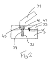
- each set 3 are attached to blocks 33 via a single axial element 35 corresponding to the axis of rotation of handle 37, see Figure 2.
- Rotation of handle 37 can be used to rotate the element 35 upwards in bore 39 and hence release the clamping action between the underside of the enlarged head 41 of the threaded element 35 and the recess 43 in the block 33.
- Rotation of the clamping set 3 relative to the block 33 and hence relative to the other clamping set 3 is provided.
- Control of the rotation of the block 33 and element 5 relative to one another is provided by a pin 45 in the top surface of the element 5 which is received in an arcuate groove 47 in the underside of the block 33.
- the groove allows rotation of 50° or so in either direction relative to the square position, but no further.
- Control of the rotation can also be provided through the use of an indexing pin which is spring loaded in the element 5 and can cooperate with a series of corresponding holes in the block 33, for instance square and at 45° in either direction.
- Rotating the handle 37 in the opposing direction locks the block 33 and element 5 in position once more.
- the blocks 33 on each of the clamping sets 3 are joined to one another by a pair of rods 53.
- the rods 53 are received in a bores 55 in the front block 33 in a fixed manner, but are slideably received in through bores 57 in the back block 33. This allows the back block to be slid back and forth, in a telescoping manner, relative to the front block as a result.
- the rear block 33 can be fixed in position by tightening handle 59.
- Telescoping the arm pairs in this way allows a variety of gaps between the pairs of arms to be provided. This enables a variety of lengths of fitting to be successfully accommodated whilst clamping close to the fitting. It also enables a clamp length 1.5 times the length of the fitting to be provided (a frequently specified requirement for recommended fitting use) for a range of different fittings, through a single clamp.
Landscapes
- Engineering & Computer Science (AREA)
- Mechanical Engineering (AREA)
- Physics & Mathematics (AREA)
- Optics & Photonics (AREA)
- Clamps And Clips (AREA)
- Portable Nailing Machines And Staplers (AREA)
- Lining Or Joining Of Plastics Or The Like (AREA)
Applications Claiming Priority (2)
| Application Number | Priority Date | Filing Date | Title |
|---|---|---|---|
| GBGB9809846.0A GB9809846D0 (en) | 1998-05-09 | 1998-05-09 | Improvements in and relating to clamping |
| GB9809846 | 1998-05-09 |
Publications (2)
| Publication Number | Publication Date |
|---|---|
| EP0958894A2 true EP0958894A2 (fr) | 1999-11-24 |
| EP0958894A3 EP0958894A3 (fr) | 2005-02-16 |
Family
ID=10831675
Family Applications (1)
| Application Number | Title | Priority Date | Filing Date |
|---|---|---|---|
| EP99303589A Withdrawn EP0958894A3 (fr) | 1998-05-09 | 1999-05-07 | Marteau agrafeur |
Country Status (2)
| Country | Link |
|---|---|
| EP (1) | EP0958894A3 (fr) |
| GB (1) | GB9809846D0 (fr) |
Cited By (5)
| Publication number | Priority date | Publication date | Assignee | Title |
|---|---|---|---|---|
| CN111015049A (zh) * | 2019-11-11 | 2020-04-17 | 大族激光科技产业集团股份有限公司 | 一种新型调节式的限位机构 |
| CN111152289A (zh) * | 2020-01-13 | 2020-05-15 | 哈尔滨学院 | 一种模型智能切割系统 |
| CN114454122A (zh) * | 2022-02-08 | 2022-05-10 | 丰民金属工业股份有限公司 | 钉枪 |
| CN117139981A (zh) * | 2023-09-13 | 2023-12-01 | 河北沧海核装备科技股份有限公司 | 一种直缝埋弧焊钢管用焊接拉拔装置 |
| DE102021120815B4 (de) * | 2021-08-10 | 2026-02-12 | OWT GmbH & Co. KG | Verfahren und selbstzentrierende fixiervorrichtung zum fixieren einer schweissvorrichtung an einem rohrabschnitt |
Family Cites Families (7)
| Publication number | Priority date | Publication date | Assignee | Title |
|---|---|---|---|---|
| GB1048935A (en) * | 1962-05-10 | 1966-11-23 | Bernard Charles Roach | Work holding clamp |
| FR1575995A (fr) * | 1967-07-11 | 1969-07-25 | ||
| DE3146258A1 (de) * | 1981-11-21 | 1983-05-26 | Bessey & Sohn Gmbh & Co, 7000 Stuttgart | Verbindungsvorrichtung fuer gripzangen |
| GB2226522B (en) * | 1988-11-26 | 1993-01-06 | Calder Technical Services Ltd | Pipe restraining clamp |
| DE3937094A1 (de) * | 1989-11-07 | 1990-05-23 | Siemens Ag | Schweissvorrichtung zum verbinden von rohren |
| DE9207334U1 (de) * | 1992-05-30 | 1992-11-19 | Simsheuser, Dietmar, Dipl.-Ing. (FH), 5489 Lückenbach | Außenzentriervorrichtung für die Zentrierung von zu verbindenden rohrförmigen Werkstücken |
| GB2301550B (en) * | 1995-01-17 | 1999-02-17 | Paul Nicholas Myers | Pipe clamping and joint assisting tool |
-
1998
- 1998-05-09 GB GBGB9809846.0A patent/GB9809846D0/en not_active Ceased
-
1999
- 1999-05-07 EP EP99303589A patent/EP0958894A3/fr not_active Withdrawn
Cited By (7)
| Publication number | Priority date | Publication date | Assignee | Title |
|---|---|---|---|---|
| CN111015049A (zh) * | 2019-11-11 | 2020-04-17 | 大族激光科技产业集团股份有限公司 | 一种新型调节式的限位机构 |
| CN111152289A (zh) * | 2020-01-13 | 2020-05-15 | 哈尔滨学院 | 一种模型智能切割系统 |
| CN111152289B (zh) * | 2020-01-13 | 2020-09-15 | 哈尔滨学院 | 一种模型智能切割系统 |
| DE102021120815B4 (de) * | 2021-08-10 | 2026-02-12 | OWT GmbH & Co. KG | Verfahren und selbstzentrierende fixiervorrichtung zum fixieren einer schweissvorrichtung an einem rohrabschnitt |
| CN114454122A (zh) * | 2022-02-08 | 2022-05-10 | 丰民金属工业股份有限公司 | 钉枪 |
| CN117139981A (zh) * | 2023-09-13 | 2023-12-01 | 河北沧海核装备科技股份有限公司 | 一种直缝埋弧焊钢管用焊接拉拔装置 |
| CN117139981B (zh) * | 2023-09-13 | 2024-02-20 | 河北沧海核装备科技股份有限公司 | 一种直缝埋弧焊钢管用焊接拉拔装置 |
Also Published As
| Publication number | Publication date |
|---|---|
| EP0958894A3 (fr) | 2005-02-16 |
| GB9809846D0 (en) | 1998-07-08 |
Similar Documents
| Publication | Publication Date | Title |
|---|---|---|
| US5971379A (en) | Adjustable magnetic jig | |
| US6431534B1 (en) | Clamping tool for aligning tubes | |
| US4747588A (en) | Universal clamping tool | |
| US7114714B2 (en) | Multifunctional workpiece clamping system | |
| EP3119557B1 (fr) | Systeme de serrage pour souder des tubes | |
| US20080256775A1 (en) | Coupling for a clamp | |
| WO2005077619A1 (fr) | Combinaison portative d'etau et de scie | |
| US5843271A (en) | Plastic pipe butt fusion machine and cart assembly | |
| US9242348B2 (en) | Interlocking clamp | |
| AU2013263011B2 (en) | Weld stress compensation system | |
| US20060157536A1 (en) | Work piece holder | |
| WO2021022120A2 (fr) | Pince à positions multiples pour opérations de soudage par friction | |
| GB2214109A (en) | Workpiece clamp | |
| US4613120A (en) | D-clamp vise | |
| US12391009B2 (en) | Chuck for gripping and moving cylindrical bodies, in particular fittings and pipe segments, and apparatus including the chuck | |
| US7172105B2 (en) | Apparatus for positioning pipe and tubing | |
| US9033328B2 (en) | Reconfigurable clamping system | |
| US20130000834A1 (en) | Pipe holding device and method of performing electrofusion with a single operator | |
| US5919335A (en) | Facer and hand held tool for joining small diameter plastic pipe | |
| CN211219711U (zh) | 一种塑胶管件加热夹具的加工固定装置 | |
| US8733750B2 (en) | 90° table mount | |
| GB2226522A (en) | Pipe welding clamp | |
| CN118848838B (zh) | 多功能快速夹钳及将快速夹钳两种夹持功能组合的方法 | |
| EP0190863B1 (fr) | Dispositif de serrage pour raccords de tuyaux | |
| US20250075732A1 (en) | Universal Vector Bushing System |
Legal Events
| Date | Code | Title | Description |
|---|---|---|---|
| PUAI | Public reference made under article 153(3) epc to a published international application that has entered the european phase |
Free format text: ORIGINAL CODE: 0009012 |
|
| AK | Designated contracting states |
Kind code of ref document: A2 Designated state(s): AT BE CH CY DE DK ES FI FR GB GR IE IT LI LU MC NL PT SE |
|
| AX | Request for extension of the european patent |
Free format text: AL;LT;LV;MK;RO;SI |
|
| RTI1 | Title (correction) |
Free format text: HAMMER-TYPE STAPLER |
|
| PUAL | Search report despatched |
Free format text: ORIGINAL CODE: 0009013 |
|
| AK | Designated contracting states |
Kind code of ref document: A3 Designated state(s): AT BE CH CY DE DK ES FI FR GB GR IE IT LI LU MC NL PT SE |
|
| AX | Request for extension of the european patent |
Extension state: AL LT LV MK RO SI |
|
| RIC1 | Information provided on ipc code assigned before grant |
Ipc: 7B 25B 5/16 B Ipc: 7B 25B 5/00 B Ipc: 7B 25B 5/10 B Ipc: 7B 25B 5/14 B Ipc: 7B 25C 5/00 B Ipc: 7B 25D 1/00 A |
|
| AKX | Designation fees paid | ||
| REG | Reference to a national code |
Ref country code: DE Ref legal event code: 8566 |
|
| STAA | Information on the status of an ep patent application or granted ep patent |
Free format text: STATUS: THE APPLICATION IS DEEMED TO BE WITHDRAWN |
|
| 18D | Application deemed to be withdrawn |
Effective date: 20050817 |