EP0958924A2 - Imprimante et tête d'impression capable d'imprimer en une pluralité de plages dynamiques de volumes de gouttelettes d'encre et leur procédé d'assemblage - Google Patents
Imprimante et tête d'impression capable d'imprimer en une pluralité de plages dynamiques de volumes de gouttelettes d'encre et leur procédé d'assemblage Download PDFInfo
- Publication number
- EP0958924A2 EP0958924A2 EP99201473A EP99201473A EP0958924A2 EP 0958924 A2 EP0958924 A2 EP 0958924A2 EP 99201473 A EP99201473 A EP 99201473A EP 99201473 A EP99201473 A EP 99201473A EP 0958924 A2 EP0958924 A2 EP 0958924A2
- Authority
- EP
- European Patent Office
- Prior art keywords
- nozzles
- nozzle
- print head
- nozzle row
- volumes
- Prior art date
- Legal status (The legal status is an assumption and is not a legal conclusion. Google has not performed a legal analysis and makes no representation as to the accuracy of the status listed.)
- Granted
Links
Images



Classifications
-
- B—PERFORMING OPERATIONS; TRANSPORTING
- B41—PRINTING; LINING MACHINES; TYPEWRITERS; STAMPS
- B41J—TYPEWRITERS; SELECTIVE PRINTING MECHANISMS, i.e. MECHANISMS PRINTING OTHERWISE THAN FROM A FORME; CORRECTION OF TYPOGRAPHICAL ERRORS
- B41J2/00—Typewriters or selective printing mechanisms characterised by the printing or marking process for which they are designed
- B41J2/005—Typewriters or selective printing mechanisms characterised by the printing or marking process for which they are designed characterised by bringing liquid or particles selectively into contact with a printing material
- B41J2/01—Ink jet
- B41J2/135—Nozzles
- B41J2/14—Structure thereof only for on-demand ink jet heads
- B41J2/14201—Structure of print heads with piezoelectric elements
- B41J2/14209—Structure of print heads with piezoelectric elements of finger type, chamber walls consisting integrally of piezoelectric material
-
- B—PERFORMING OPERATIONS; TRANSPORTING
- B41—PRINTING; LINING MACHINES; TYPEWRITERS; STAMPS
- B41J—TYPEWRITERS; SELECTIVE PRINTING MECHANISMS, i.e. MECHANISMS PRINTING OTHERWISE THAN FROM A FORME; CORRECTION OF TYPOGRAPHICAL ERRORS
- B41J2/00—Typewriters or selective printing mechanisms characterised by the printing or marking process for which they are designed
- B41J2/005—Typewriters or selective printing mechanisms characterised by the printing or marking process for which they are designed characterised by bringing liquid or particles selectively into contact with a printing material
- B41J2/01—Ink jet
- B41J2/015—Ink jet characterised by the jet generation process
- B41J2/04—Ink jet characterised by the jet generation process generating single droplets or particles on demand
- B41J2/045—Ink jet characterised by the jet generation process generating single droplets or particles on demand by pressure, e.g. electromechanical transducers
- B41J2/04501—Control methods or devices therefor, e.g. driver circuits, control circuits
- B41J2/04581—Control methods or devices therefor, e.g. driver circuits, control circuits controlling heads based on piezoelectric elements
-
- B—PERFORMING OPERATIONS; TRANSPORTING
- B41—PRINTING; LINING MACHINES; TYPEWRITERS; STAMPS
- B41J—TYPEWRITERS; SELECTIVE PRINTING MECHANISMS, i.e. MECHANISMS PRINTING OTHERWISE THAN FROM A FORME; CORRECTION OF TYPOGRAPHICAL ERRORS
- B41J2/00—Typewriters or selective printing mechanisms characterised by the printing or marking process for which they are designed
- B41J2/005—Typewriters or selective printing mechanisms characterised by the printing or marking process for which they are designed characterised by bringing liquid or particles selectively into contact with a printing material
- B41J2/01—Ink jet
- B41J2/015—Ink jet characterised by the jet generation process
- B41J2/04—Ink jet characterised by the jet generation process generating single droplets or particles on demand
- B41J2/045—Ink jet characterised by the jet generation process generating single droplets or particles on demand by pressure, e.g. electromechanical transducers
- B41J2/04501—Control methods or devices therefor, e.g. driver circuits, control circuits
- B41J2/04588—Control methods or devices therefor, e.g. driver circuits, control circuits using a specific waveform
-
- B—PERFORMING OPERATIONS; TRANSPORTING
- B41—PRINTING; LINING MACHINES; TYPEWRITERS; STAMPS
- B41J—TYPEWRITERS; SELECTIVE PRINTING MECHANISMS, i.e. MECHANISMS PRINTING OTHERWISE THAN FROM A FORME; CORRECTION OF TYPOGRAPHICAL ERRORS
- B41J2/00—Typewriters or selective printing mechanisms characterised by the printing or marking process for which they are designed
- B41J2/005—Typewriters or selective printing mechanisms characterised by the printing or marking process for which they are designed characterised by bringing liquid or particles selectively into contact with a printing material
- B41J2/01—Ink jet
- B41J2/015—Ink jet characterised by the jet generation process
- B41J2/04—Ink jet characterised by the jet generation process generating single droplets or particles on demand
- B41J2/045—Ink jet characterised by the jet generation process generating single droplets or particles on demand by pressure, e.g. electromechanical transducers
- B41J2/04501—Control methods or devices therefor, e.g. driver circuits, control circuits
- B41J2/04593—Dot-size modulation by changing the size of the drop
-
- B—PERFORMING OPERATIONS; TRANSPORTING
- B41—PRINTING; LINING MACHINES; TYPEWRITERS; STAMPS
- B41J—TYPEWRITERS; SELECTIVE PRINTING MECHANISMS, i.e. MECHANISMS PRINTING OTHERWISE THAN FROM A FORME; CORRECTION OF TYPOGRAPHICAL ERRORS
- B41J2/00—Typewriters or selective printing mechanisms characterised by the printing or marking process for which they are designed
- B41J2/005—Typewriters or selective printing mechanisms characterised by the printing or marking process for which they are designed characterised by bringing liquid or particles selectively into contact with a printing material
- B41J2/01—Ink jet
- B41J2/21—Ink jet for multi-colour printing
- B41J2/2121—Ink jet for multi-colour printing characterised by dot size, e.g. combinations of printed dots of different diameter
- B41J2/2125—Ink jet for multi-colour printing characterised by dot size, e.g. combinations of printed dots of different diameter by means of nozzle diameter selection
-
- B—PERFORMING OPERATIONS; TRANSPORTING
- B41—PRINTING; LINING MACHINES; TYPEWRITERS; STAMPS
- B41J—TYPEWRITERS; SELECTIVE PRINTING MECHANISMS, i.e. MECHANISMS PRINTING OTHERWISE THAN FROM A FORME; CORRECTION OF TYPOGRAPHICAL ERRORS
- B41J2/00—Typewriters or selective printing mechanisms characterised by the printing or marking process for which they are designed
- B41J2/005—Typewriters or selective printing mechanisms characterised by the printing or marking process for which they are designed characterised by bringing liquid or particles selectively into contact with a printing material
- B41J2/01—Ink jet
- B41J2/135—Nozzles
- B41J2/14—Structure thereof only for on-demand ink jet heads
- B41J2002/14475—Structure thereof only for on-demand ink jet heads characterised by nozzle shapes or number of orifices per chamber
-
- B—PERFORMING OPERATIONS; TRANSPORTING
- B41—PRINTING; LINING MACHINES; TYPEWRITERS; STAMPS
- B41J—TYPEWRITERS; SELECTIVE PRINTING MECHANISMS, i.e. MECHANISMS PRINTING OTHERWISE THAN FROM A FORME; CORRECTION OF TYPOGRAPHICAL ERRORS
- B41J2202/00—Embodiments of or processes related to ink-jet or thermal heads
- B41J2202/01—Embodiments of or processes related to ink-jet heads
- B41J2202/19—Assembling head units
-
- B—PERFORMING OPERATIONS; TRANSPORTING
- B41—PRINTING; LINING MACHINES; TYPEWRITERS; STAMPS
- B41J—TYPEWRITERS; SELECTIVE PRINTING MECHANISMS, i.e. MECHANISMS PRINTING OTHERWISE THAN FROM A FORME; CORRECTION OF TYPOGRAPHICAL ERRORS
- B41J2202/00—Embodiments of or processes related to ink-jet or thermal heads
- B41J2202/01—Embodiments of or processes related to ink-jet heads
- B41J2202/21—Line printing
Definitions
- the present invention generally relates to printing apparatus and methods and more particularly relates to a printer and print head capable of printing in a plurality of dynamic ranges of ink droplet volumes, and method of assembling same.
- An ink jet printer produces images on a receiver medium by ejecting ink droplets onto the receiver medium in an image-wise fashion.
- the advantages of non-impact, low-noise, low energy use, and low cost operation in addition to the capability of the printer to print on plain paper are largely responsible for the wide acceptance of ink jet printers in the marketplace.
- ink jet printers are used in a variety of applications.
- an ink jet printer may be required to print an image having a single density level at 180 dpi ( d ots p er i nch) for outdoor signage.
- This density level for outdoor signage is aesthetically acceptable because such images are typically viewed from a relatively long distance (for example, 30 feet or 9.14 meters) away from the image.
- Ink jet printers are also called upon to print relatively high quality images having 16 density levels at 1440 dpi, such as in the case of 8 by 10 inch (20.32 by 25.4 centimeters) photographs.
- This density level for photographs is aesthetically desirable because photographs are typically viewed from a relatively short distance (for example, 6 inches or 15.24 centimeters) away from the viewer.
- dynamic range is commonly defined in the art to mean the range of minimum ink droplet volume to the maximum ink droplet volume which is provided by one ink nozzle. That is, each individual ink jet printer possesses a density range particularly suited for its intended use. For example, an ink jet printer used for signage typically has a density range different from the density range of an ink jet printer used for photographs. Clearly, for purposes of economy, it is desirable to have the same ink jet printer print in both low density and high density ranges.
- Ink jet printers having continuous tone to high resolution printing performance are known.
- One such printer is disclosed in U.S. Patent 5,412,410 titled “Ink Jet Printhead For continuous Tone And Text Printing” issued May 2, 1995, in the name of Ivan Rezanka.
- the Rezanka device provides a thermal ink jet print head both for continuous tone printing and high resolution printing by controlling the area covered by the ink at each pixel location of the printed image.
- the print head includes at least two different groups of differently sized nozzles from which ink droplets of different ink volumes are selectively ejected.
- nozzles of one group, or both groups may be selectively used to print continuous tone and/or high resolution text.
- the Rezanka device is capable of ejecting 16 to 256 different ink droplet volumes in a suitable manner. That is, it appears that the Rezanka device requires 16 to 256 nozzle groups to print 16 to 256 ink droplet volumes for a pixel in an image. Manufacturing such a great number of nozzles increases manufacturing and assembly costs of the printer and associated print head. Also, the Rezanka device appears to permit only a relatively small number of nozzles of a given nozzle diameter within each nozzle group. That is, it appears from the Rezanka disclosure that if a total of 256 nozzles having 256 nozzle sizes are present in a print head, there is only one nozzle for each nozzle diameter.
- the nozzle diameter may only be varied in a limited range to permit effective ink droplet ejection.
- the nozzle diameter is tool large, ink tends to in advertently seep-out the nozzle.
- the nozzle diameter is too small, viscosity forces acting at the nozzle wall will be too high for ink ejection.
- This limitation in variation of nozzle diameter further reduces the range of ink drop volumes that can be provided by prior art devices, such as the Rezanka device. Therefore, a problem in the art is limited range of ink drop volumes produced by ink jet printers.
- an object of the present invention is to provide a printer and print head capable of printing in a plurality of dynamic ranges of ink droplet volumes, so that the number of ink ejection nozzles are minimized, and method of assembling the printer and print head.
- the present invention resides in a printer, comprising a print head body; a first nozzle connected to said print head body, said first nozzle having a first nozzle orifice of a first size for ejecting fluid therethrough having a first volume selected from a first dynamic range of volumes associated with said first nozzle; and a second nozzle connected to said print head body, said second nozzle having a second nozzle orifice of a second size different from the first size of the first orifice for ejecting fluid therethrough having a second volume different from the first volume, the second volume being selected from a second dynamic range of volumes associated with said second nozzle, the second dynamic range of volumes being substantially different from the first dynamic range of volumes.
- a plurality of first nozzles are connected to a print head body, each first nozzle having a first orifice of a first size for ejecting an ink droplet having a first volume.
- the ink droplet volume is selected from a first dynamic range of volumes.
- dynamic range is defined herein to mean the range of minimum ink droplet volume to the maximum ink droplet volume which is provided by one ink nozzle.
- the first dynamic range of volumes is uniquely associated with each first nozzle.
- a plurality of second nozzles are also connected to the print head body, each second nozzle having a second orifice of a second size larger than the first size of the first nozzles for ejecting an ink droplet therethrough having a second volume larger than the first volume.
- the second volume is selected from a second dynamic range of volumes.
- the second dynamic range of volumes is uniquely associated with each second nozzle.
- the second dynamic range of volumes is substantially different from the first dynamic range of volumes.
- the second dynamic range of volumes may be greater than the first dynamic range of volumes.
- first nozzles are arranged to define a first nozzle row and the second nozzles are arranged to define a second nozzle row adjacent the first nozzle row, so that the first nozzles defining the first row are co-linearly aligned with respective ones of the second nozzles defining the second row.
- first nozzles can be arranged to define the first nozzle row and the second nozzles can be arranged to define the second nozzle row adjacent the first nozzle row, such that the first nozzles defining the first row are off-set relative to respective ones of the second nozzles defining the second row.
- a feature of the present invention is the provision of a nozzle plate comprising nozzles having nozzle orifices arranged in rows according to orifice size, so that orifices of the same size are assigned to the same row of orifices.
- Another feature of the present invention is the provision of a nozzle plate, wherein one nozzle orifice from each row of nozzles define a pixel group, the nozzle orifices defining the pixel group are adjacent to each other.
- An advantage of the present invention is that dynamic range in ink droplet volume provided by each pixel group is significantly larger than what is provided by prior art thermal ink jet printers.
- Another advantage of the present invention is that when a relatively wide density range is required, enablement of all nozzles in a pixel group can provide a maximum dynamic range in ink droplet volume.
- a first nozzle row and a second nozzle row can each provide 4 bits of volume variation with respect to ink droplet volume, so that 8 bits of volume variation is obtained when both the first and second nozzles are used in combination.
- Still another advantage of the present invention is that the printer is capable of printing images at high speed and low resolution in a single bit density variation (that is, halftone images) which is suitable for signs viewed from a relatively long distance.
- the same printer can also print in multi-bit density levels at high resolution, which is suitable for viewing photographic quality images.
- printer 10 capable of printing in a plurality of dynamic ranges of ink droplet volume.
- printer 10 is capable of ejecting an ink droplet 20 (see Fig. 5) from a print head 25 toward a receiver 30 in order to form an image 35 on receiver 30.
- Receiver 30 may be a reflective-type (for example, paper) or transmissive-type (for example, transparency) receiver.
- Print head 25 includes a generally cuboid-shaped preferably one-piece print head body 27 (see Fig. 2), as disclosed more fully hereinbelow.
- dynamic range means the range of minimum ink droplet volume to the maximum ink droplet volume which is provided by one ink nozzle.
- printer 10 comprises an image source 40, which may be raster image data from a scanner or computer, or outline image data in the form of a PDL ( P age D escription L anguage) or other form of digital image representation.
- image data is transmitted to an image processor 50 connected to image source 40.
- image processor 50 converts the image data to a pixel-mapped page image.
- Image processor 50 may be a raster image processor in the case of PDL image data to be convened, or a pixel image processor in the case of raster image data to be convened.
- image processor 50 transmits continuous tone data to a digital halftoning unit 60 connected to image processor 50.
- Halftoning unit 60 halftones the continuous tone data produced by image processor 50 and produces halftoned bitmap image data that is stored in an image memory 70, which may be a full-page memory or a band memory depending on the configuration of printer 10.
- a pulse generator 80 connected to image memory 70 reads data from image memory 70 and applies time and amplitude varying voltage pulses to an electrical actuator 90 (see Fig. 2), for reasons described more fully hereinbelow.
- receiver 30 is moved relative to print head 25 by means of a transport mechanism 100, which is electronically controlled by a transport control system 110.
- Transport control system 110 in turn is controlled by a suitable controller 120.
- a suitable controller 120 It may be appreciated that different mechanical configurations for transport control system 110 are possible. For example, in the case of pagewidth print heads, it is convenient to move receiver 30 past a stationary print head 25. On the other hand, in the case of scanning-type print systems, it is more convenient to move print head 25 along one axis (that is, a sub-scanning direction) and receiver 30 along an orthogonal axis (that is, a main scanning direction), in a relative raster motion.
- controller 120 may be connected to an ink pressure regulator 130 for controlling regulator 130.
- Regulator 130 if present, is connected to an ink reservoir 140, such as by means of a first conduit 135, for regulating pressure in ink reservoir 140.
- Ink reservoir 140 is connected, such as by means of a second conduit 150, to print head 25 for supplying ink to print head 25.
- print head 25 comprises the previously mentioned generally cuboid-shaped preferably one-piece print head body 27 formed of a piezoelectric material.
- the piezoelectric material such as lead zirconium titanate (PZT)
- PZT lead zirconium titanate
- piezoelectric print head body 27 is "poled" generally in the direction of an arrow 160.
- the poling direction may be oriented in other directions, if desired, such as in a direction perpendicular to the poling direction shown by arrow 160.
- a plurality of elongate ink channels 170 cut into print head body 27 are a plurality of elongate ink channels 170.
- Each of the channels 170 has a channel outlet 175 at an end 176 thereof and an open side 177.
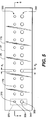
- Ink channels 170 are covered at outlets 175 by a first embodiment nozzle plate 178 (see Fig. 5) having a plurality of orifices 179 of predetermined diameter aligned with respective ones of channels 170, so that ink droplets 20 are ejected from channels 170 and through their respective orifices 179.
- a rear cover plate (not shown) is also provided for capping the rear of channels 175.
- a top cover plate caps chambers 170 along open side 177.
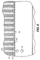
- print head body 27 includes a first side wall 180 and a second side wall 190 defining channel 170 therebetween, which channel 170 is adapted to receive liquid ink body 200 (see Fig. 6) therein.
- first side wall 180 has an outside surface 203 and second side wall 190 has an outside surface 205.
- Print head body 27 also includes a base portion 210 interconnecting first side wall 180 and second side wall 190, so as to form a generally U-shaped structure comprising the piezoelectric material. Upper-most surfaces (as shown) of first side wall 180 and second side wall 190 together define a top surface 220 of print head body 27.
- a lower-most surface (as shown) of base portion 210 defines a bottom surface 230 of print head body 27.
- An addressable electrode actuator layer 240 may extend from approximately half-way up outside surface 203 of first side wall 180, across bottom surface 230 to approximately half-way up outside surface 195. In this configuration of electrode actuator layer 240, an electrical field "E" (not shown) is established in a predetermined orientation with respect to poling direction 160, as described in more detail hereinbelow.
- electrode actuator layer 240 is connected to the previously mentioned pulse generator 80. Pulse generator 80 supplies electrical drive signals to electrode actuator layer 240 via an electrical conducting terminal 250 interconnecting pulse generator 80 and actuator layer 240.
- a common electrode layer 260 coats each channel 170 and also extends therefrom along top surface 220.
- Common electrode layer 260 is preferably connected to a ground electric potential, as at a point 270.
- common electrode layer 290 may be connected to pulse generator 80 for receiving electrical drive signals therefrom.
- it is preferable to maintain common electrode layer 260 at ground potential because common electrode layer 260 is in contact with liquid ink body 200 in channel 170. That is, it is preferable to maintain common electrode layer 260 at ground potential in order to minimize electrolysis effects on common electrode layer 260 when in contact with liquid ink body 200 in channel 170, which electrolysis may otherwise act to degrade performance of common electrode layer 260 as well as the ink.
- each pair of “neighboring" ink channels 170 is separated by a cut-out 280, which may be filled with air or a resilient elastomer (not shown), for reducing mechanical "cross-talk" between channels 170.
- a cut-out 280 is defined between respective pairs of side walls 180/190, so that channels 170 are mechanically decoupled by presence of cut-outs 280. It should be apparent from the description herein that the terminology "neighboring" ink channels means ink channels 170 that would otherwise be adjacent but for intervening cut-out 280.
- pulse generator 80 generates an electrical drive signal comprising an electrical pulse burst 290 which is supplied to electrode actuator layer 240 by means of electrical conducting terminal 250.
- Pulse burst 290 which may comprise a plurality of sinusoidal pulses 295, has a predetermined peak voltage amplitude V p (either positive or negative) and a period T 1 .
- Print head body 27, which is responsive to the electrical stimuli supplied to electrode actuator layer 240 by generator 80 deforms when pulse burst 290 is applied, so that first side wall 180 and second side wall 190 simultaneously inwardly move toward each other.
- base portion 210 will likewise inwardly move, as the electrical stimuli is supplied to actuator 240. That is, first side wall 180, second side wall 190 and base portion 210 move due to the inherent nature of piezoelectric materials, such as the piezoelectric material forming print head body 27. In this regard, it is known that when an electrical signal is applied to a piezoelectric material, mechanical distortion occurs in the piezoelectric material. This mechanical distortion is dependent on the poling direction and the direction of the applied electrical field "E" (not shown).
- the previously mentioned electric field "E” is established between electrode actuator layer 240 and common electrode layer 260 and is in a direction generally parallel to poling direction 160 near base portion 210 in order to cause base portion 210 to deform and compress in non-shear mode.
- electric field "E” is in a direction generally perpendicular to poling direction 160 near side walls 180/190 to cause side walls 180/190 to deform in shear mode. That is, side walls 180/190 will deform into a generally parallelogram shape, rather than the compressed shape in which base portion 210 deforms. In this manner, print head body 27 becomes longer and thinner in a direction parallel to poling direction 160.
- peak voltage amplitude, either +Vp or -Vp, and periods T 1 may be identical for each pulse 295 (see Fig. 4A). Having identical peak voltage amplitude and period T 1 is often preferred because it simplifies manufacture and assembly of electronics that provide electrical drive signals to actuator layer 240. Alternatively, it may be appreciated that peak voltage amplitude, either +Vp or -Vp, and periods T 1 and T 1 ' may be different for each pulse 295 (see Fig. 4B). Having different peak voltage amplitudes and periods T 1 and T 1 ' provides flexibility in producing individual microdroplets (not shown) within a burst of ink droplets 20. Such microdroplets may combine in flight to produce a macrodroplet which is deposited on receiver 30.
- peak voltage amplitudes may be different for each half period T 2 and T 2 ' (see Fig. 4C). Having different peak voltage amplitudes for each half period T 2 provides even more flexibility in compressing and expanding first and second side walls 180/190 of ink channels 170. In this manner, actuation forces for compressing (that is, inwardly moving) and expanding (that is, outwardly moving) first and second side walls 180/190 do not have to be identical for each half-period T 2 and T 2 '.
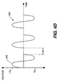
- a time delay " ⁇ t" may be inserted between pulses 295, if desired, to spatially separate the microdroplets (see Fig. 4D).
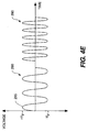
- the number of pulses 295 in each pulse burst 290 can be varied, if desired, so that number of microdroplets are varied within each burst of ink droplets (see Fig. 4E).
- a series of "n" micro-droplets can be ejected from nozzles print head 25 when driven by a burst of "n" pulses.
- Such micro-droplets combine into a macro-droplet (that is, droplet 20) which in turn is deposited onto receiver 30.
- one micro-droplet corresponds to a droplet volume of approximately 1 pl.
- first embodiment nozzle plate 178 which is connected to print head body 25, includes a plurality of first nozzles 310, each first nozzle 310 having a first orifice 320 of a first diameter "d 1 " for ejecting a plurality of ink droplets 20 therethrough.
- First nozzles 310 are arranged so as to define a first nozzle row 330 (as shown).
- Each ink droplet 20 ejected through each first orifice 320 has a first volume selected from a first dynamic range of volumes associated with each first nozzle 310 in first nozzle row 330.
- nozzle plate 178 includes a plurality of second nozzles 340, each second nozzle 340 having a second orifice 350 of a second diameter "d 2 " for ejecting a plurality of ink droplets 20 therethrough.
- Second nozzles 340 are ranged to define a second nozzle row 360 (as shown).
- Each ink droplet 20 ejected through each second orifice 350 has a second volume selected from a second dynamic range of volumes associated with each second nozzle 340 in second nozzle row 360.
- ranges in ink droplet volume is a function of the geometry of channel 170, number of pulses 295 in a pulse burst 290, peak voltages +V p , or -V p , as well as orifice diameter (that is, d 1 or d 2 ). It has also been discovered that nozzle orifice diameter pay a crucial role in determining ink droplet volume. With respect to nozzle orifice diameters, a plurality (for example, two) of nozzle diameters can be used to influence ink droplet volume which is ejected from first nozzle row 330 and second nozzle row 360.
- first nozzles 310 comprising first nozzle row 330 are capable of ejecting ink droplets 20 having volumes ranging from 1 to 16 pl ( p ico- l itres).
- second nozzles 340 comprising second nozzle row 360 are capable of ejecting ink droplets 20 having volumes ranging from 16 pl, 32 pl, 48 pl, and up to 256 pl. Therefore, second nozzles 340 possess a larger range of volumes compared to first nozzles 310.
- each pair of immediately adjacent nozzles 310/340 are ranged into pixel group 370.
- ink droplet volumes that can be ejected by pixel group 370 range from 1 pl to 256 pl.
- each first nozzle 310 in pixel group 370 can eject an ink droplet volume ranging from 1 to 16 pl and each second nozzle 340 in pixel group 370 can eject an ink droplet volume ranging from 16 pl, 32 pl, 48 pl, and up to 256 pl.
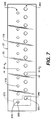
- first nozzles 310 are staggered with respect to second nozzles 340.
- An advantage of this configuration of nozzle plate 178 is that staggered nozzles 310/340 can place ink droplets in one printing pass at different pixel locations, so that ink coalescence on receiver 30 is reduced,
- a third embodiment of the invention comprising a first print head 380a and a second print head 380b disposed parallel to first print head 380a.
- a first nozzle plate 390a is connected to first print head 380a and a second nozzle plate 390b is connected to second print head 390b.
- the advantage of this configuration of the invention is the same as the advantages disclosed herein for the previously mentioned embodiments of the invention.
- another advantage associated with this third embodiment of the invention is enhanced flexibility of manufacturing and assembling print heads 380a/380b.
- each print head 380a/380b and associated nozzle plates 390a/390b are separately manufactured. These different print heads 380a/380b can then be packaged together to form a combined print head.
- first nozzle row 330 and second nozzle row 360 can each provides 4 bits of volume variation with respect to ink droplet volume.
- first nozzle row 330 and second nozzle row 360 can each provide 4 bits of volume variation with respect to ink droplet volume.
- only the nozzles 310/340 belonging to pixel group 370 are needed to provide 8 bits of ink volume variation. This is an improvement over the prior art which requires a significantly greater number of nozzles to achieve similar results.
- Another advantage of the present invention is that dynamic range in ink droplet volume within each pixel group 370 is significantly larger than what is provided by prior art thermal ink jet printers. This result allows a single printer to print a single density level at 180 dpi or 16 density levels at 1440 dpi.
- print head 25 is capable of printing images at high speed and low resolution in a single bit density variation (that is, halftone images), which is suitable for signs viewed from a relatively long distance. That is, print head 25 can print signage at 180 dpi in a single density level per pixel. Moreover, print head 25 can also print in multi-bit density levels at high resolution, which is suitable for viewing photographic quality printed images from a relatively short distance. That is, print head 25 can print photographic quality images at 1440 dpi in multiple density levels per pixel.
- yet another advantage of the present invention is that when a relatively wide density range is required, enablement of all ink nozzles 310/340 in a pixel group 370 can provide maximum dynamic range in ink droplet volume.
- pulses 295 are disclosed herein as sinusoidal. However, pulses 295 may assume other shapes as well, such as square, trapezoidal or triangular or any other analog waveform.
- a printer and print head body capable of printing in a plurality of dynamic ranges of ink volumes, and method of assembling the printer and print head.
Landscapes
- Particle Formation And Scattering Control In Inkjet Printers (AREA)
Applications Claiming Priority (2)
| Application Number | Priority Date | Filing Date | Title |
|---|---|---|---|
| US09/081,984 US6328399B1 (en) | 1998-05-20 | 1998-05-20 | Printer and print head capable of printing in a plurality of dynamic ranges of ink droplet volumes and method of assembling same |
| US81984 | 2001-11-13 |
Publications (3)
| Publication Number | Publication Date |
|---|---|
| EP0958924A2 true EP0958924A2 (fr) | 1999-11-24 |
| EP0958924A3 EP0958924A3 (fr) | 2000-05-31 |
| EP0958924B1 EP0958924B1 (fr) | 2008-06-04 |
Family
ID=22167661
Family Applications (1)
| Application Number | Title | Priority Date | Filing Date |
|---|---|---|---|
| EP99201473A Expired - Lifetime EP0958924B1 (fr) | 1998-05-20 | 1999-05-12 | Imprimante et tête d'impression capable d'imprimer en une pluralité de plages dynamiques de volumes de gouttelettes d'encre et leur procédé d'assemblage |
Country Status (4)
| Country | Link |
|---|---|
| US (1) | US6328399B1 (fr) |
| EP (1) | EP0958924B1 (fr) |
| JP (1) | JPH11342639A (fr) |
| DE (1) | DE69938856D1 (fr) |
Cited By (7)
| Publication number | Priority date | Publication date | Assignee | Title |
|---|---|---|---|---|
| EP1138497A3 (fr) * | 2000-03-30 | 2002-02-06 | Hewlett-Packard Company | Tête d'impression comprenant plusieurs types de générateurs de gouttes |
| EP1228878A1 (fr) * | 2001-01-31 | 2002-08-07 | Canon Kabushiki Kaisha | Traitement de données d'impression pour un dispositif d'impression |
| GB2410468A (en) * | 2004-01-30 | 2005-08-03 | Hewlett Packard Development Co | Nozzle distribution |
| EP1995069A1 (fr) * | 2007-05-25 | 2008-11-26 | Canon Kabushiki Kaisha | Tête d'éjection de liquide et appareil d'impression par jet d'encre |
| CN102294895A (zh) * | 2010-06-24 | 2011-12-28 | 精工爱普生株式会社 | 液体喷射装置以及液体喷射装置的控制方法 |
| EP2894683A1 (fr) * | 2013-12-30 | 2015-07-15 | Samsung Electro-Mechanics Co., Ltd. | Appareil et procédé de commande d'élément piézoélectrique et système piézoélectrique l'utilisant |
| CN107531049A (zh) * | 2015-07-14 | 2018-01-02 | 惠普发展公司有限责任合伙企业 | 流体再循环通道 |
Families Citing this family (17)
| Publication number | Priority date | Publication date | Assignee | Title |
|---|---|---|---|---|
| US6547352B1 (en) * | 1999-06-25 | 2003-04-15 | Matsushita Electric Industrial Co., Ltd. | Ink jet recording device |
| US6705711B1 (en) | 2002-06-06 | 2004-03-16 | Oće Display Graphics Systems, Inc. | Methods, systems, and devices for controlling ink delivery to one or more print heads |
| US7040729B2 (en) * | 2002-06-06 | 2006-05-09 | Oce Display Graphics Systems, Inc. | Systems, methods, and devices for controlling ink delivery to print heads |
| US7052117B2 (en) | 2002-07-03 | 2006-05-30 | Dimatix, Inc. | Printhead having a thin pre-fired piezoelectric layer |
| US8491076B2 (en) | 2004-03-15 | 2013-07-23 | Fujifilm Dimatix, Inc. | Fluid droplet ejection devices and methods |
| US7281778B2 (en) | 2004-03-15 | 2007-10-16 | Fujifilm Dimatix, Inc. | High frequency droplet ejection device and method |
| US7258410B2 (en) * | 2004-11-10 | 2007-08-21 | Xerox Corporation | Method and apparatus for reducing intercolor bleed to improve print quality |
| EP1836056B1 (fr) | 2004-12-30 | 2018-11-07 | Fujifilm Dimatix, Inc. | Impression a jet d'encre |
| US7988247B2 (en) | 2007-01-11 | 2011-08-02 | Fujifilm Dimatix, Inc. | Ejection of drops having variable drop size from an ink jet printer |
| JP2009113425A (ja) * | 2007-11-08 | 2009-05-28 | Seiko Epson Corp | 液体吐出装置 |
| JP5217366B2 (ja) * | 2007-11-08 | 2013-06-19 | セイコーエプソン株式会社 | 液体吐出装置 |
| US8419145B2 (en) | 2008-07-25 | 2013-04-16 | Eastman Kodak Company | Inkjet printhead and method of printing with multiple drop volumes |
| US8393702B2 (en) | 2009-12-10 | 2013-03-12 | Fujifilm Corporation | Separation of drive pulses for fluid ejector |
| JP6111571B2 (ja) * | 2012-09-06 | 2017-04-12 | 東洋製罐株式会社 | インクジェット印刷装置及び円筒形状容器への印刷方法 |
| WO2016068948A1 (fr) * | 2014-10-30 | 2016-05-06 | Hewlett-Packard Development Company, L.P. | Impression a jet d'encre |
| CN107073959B (zh) * | 2014-10-30 | 2019-11-12 | 惠普发展公司,有限责任合伙企业 | 用于打印文档的方法、打印系统以及非暂时性机器可读介质 |
| WO2016068946A1 (fr) * | 2014-10-30 | 2016-05-06 | Hewlett-Packard Development Company, L.P. | Impression à jet d'encre |
Citations (1)
| Publication number | Priority date | Publication date | Assignee | Title |
|---|---|---|---|---|
| US5412410A (en) | 1993-01-04 | 1995-05-02 | Xerox Corporation | Ink jet printhead for continuous tone and text printing |
Family Cites Families (7)
| Publication number | Priority date | Publication date | Assignee | Title |
|---|---|---|---|---|
| JPS55131882A (en) | 1979-04-02 | 1980-10-14 | Canon Inc | Electronic equipment |
| JPS5812764A (ja) * | 1981-07-16 | 1983-01-24 | Fujitsu Ltd | インクジエツト記録方式 |
| US4746935A (en) | 1985-11-22 | 1988-05-24 | Hewlett-Packard Company | Multitone ink jet printer and method of operation |
| US5726690A (en) | 1991-05-01 | 1998-03-10 | Hewlett-Packard Company | Control of ink drop volume in thermal inkjet printheads by varying the pulse width of the firing pulses |
| DE9209505U1 (de) | 1992-07-15 | 1992-09-24 | Fichtel & Sachs Ag, 8720 Schweinfurt | Ventilbaugruppe für einen Schwingungsdämpfer mit veränderbarer Dämpfkraft |
| DE69534683T2 (de) | 1994-12-29 | 2006-07-06 | Canon K.K. | Tintenstrahlkopf mit verschiedenen Heizelementen pro Düse und Tintenstrahldrucker unter Verwendung desselben |
| AUPN232195A0 (en) | 1995-04-12 | 1995-05-04 | Eastman Kodak Company | Multiple simultaneous drop sizes in proximity lift printing |
-
1998
- 1998-05-20 US US09/081,984 patent/US6328399B1/en not_active Expired - Lifetime
-
1999
- 1999-05-12 DE DE69938856T patent/DE69938856D1/de not_active Expired - Lifetime
- 1999-05-12 EP EP99201473A patent/EP0958924B1/fr not_active Expired - Lifetime
- 1999-05-20 JP JP11140141A patent/JPH11342639A/ja active Pending
Patent Citations (1)
| Publication number | Priority date | Publication date | Assignee | Title |
|---|---|---|---|---|
| US5412410A (en) | 1993-01-04 | 1995-05-02 | Xerox Corporation | Ink jet printhead for continuous tone and text printing |
Cited By (12)
| Publication number | Priority date | Publication date | Assignee | Title |
|---|---|---|---|---|
| EP1138497A3 (fr) * | 2000-03-30 | 2002-02-06 | Hewlett-Packard Company | Tête d'impression comprenant plusieurs types de générateurs de gouttes |
| EP1228878A1 (fr) * | 2001-01-31 | 2002-08-07 | Canon Kabushiki Kaisha | Traitement de données d'impression pour un dispositif d'impression |
| US6877833B2 (en) | 2001-01-31 | 2005-04-12 | Canon Kabushiki Kaisha | Printing data producing method for printing apparatus |
| GB2410468A (en) * | 2004-01-30 | 2005-08-03 | Hewlett Packard Development Co | Nozzle distribution |
| US7249815B2 (en) | 2004-01-30 | 2007-07-31 | Hewlett-Packard Development Company, L.P. | Nozzle distribution |
| GB2410468B (en) * | 2004-01-30 | 2008-09-03 | Hewlett Packard Development Co | Nozzle distribution |
| EP1995069A1 (fr) * | 2007-05-25 | 2008-11-26 | Canon Kabushiki Kaisha | Tête d'éjection de liquide et appareil d'impression par jet d'encre |
| US7887159B2 (en) | 2007-05-25 | 2011-02-15 | Canon Kabushiki Kaisha | Liquid ejecting head and ink jet printing apparatus |
| CN102294895A (zh) * | 2010-06-24 | 2011-12-28 | 精工爱普生株式会社 | 液体喷射装置以及液体喷射装置的控制方法 |
| EP2894683A1 (fr) * | 2013-12-30 | 2015-07-15 | Samsung Electro-Mechanics Co., Ltd. | Appareil et procédé de commande d'élément piézoélectrique et système piézoélectrique l'utilisant |
| US9680084B2 (en) | 2013-12-30 | 2017-06-13 | Mplus Co., Ltd. | Piezoelectric element driving apparatus and method, and piezoelectric system using the same |
| CN107531049A (zh) * | 2015-07-14 | 2018-01-02 | 惠普发展公司有限责任合伙企业 | 流体再循环通道 |
Also Published As
| Publication number | Publication date |
|---|---|
| US6328399B1 (en) | 2001-12-11 |
| DE69938856D1 (de) | 2008-07-17 |
| JPH11342639A (ja) | 1999-12-14 |
| EP0958924B1 (fr) | 2008-06-04 |
| EP0958924A3 (fr) | 2000-05-31 |
Similar Documents
| Publication | Publication Date | Title |
|---|---|---|
| EP0958924B1 (fr) | Imprimante et tête d'impression capable d'imprimer en une pluralité de plages dynamiques de volumes de gouttelettes d'encre et leur procédé d'assemblage | |
| AU687067B2 (en) | Droplet volume modulation techniques for ink jet printheads | |
| US6234605B1 (en) | Multiple resolution pagewidth ink jet printer including a positionable pagewidth printbear | |
| US6536873B1 (en) | Drop-on-demand ink jet printer capable of directional control of ink drop ejection and method of assembling the printer | |
| JP3601364B2 (ja) | 流体噴射装置及びインク滴噴射方法 | |
| DE69820201T2 (de) | Verfahren zum antreiben eines tintenstrahlaufzeichnungskopfes | |
| DE60026919T2 (de) | Vorrichtung und Verfahren zur Modulation der Tropfengrösse beim Tintenstrahldrucken | |
| EP0963844A1 (fr) | Imprimante et procédé adaptés pour réduire la variabilité du volume des gouttelettes d'encre ejectées | |
| US6471322B2 (en) | Ink-jet recording method and ink-jet recording apparatus | |
| US8434842B2 (en) | Liquid ejecting apparatus and method of controlling liquid ejecting apparatus | |
| JPH08510420A (ja) | 高周波数ドロップオンデマンド型インクジェットシステム | |
| EP0855277A2 (fr) | Tête d'impression à jet d'encre adaptée à la modulation de la taille des gouttes | |
| JP2002160358A (ja) | インクジェットプリントヘッドの作動方法 | |
| EP0988973A1 (fr) | Appareil d'imagerie capable d'empêcher l'éjection involontaire d'une goutellette d'encre satellite et procédé d'assemblage de l'appareil | |
| US6457818B1 (en) | Ink jet type recording head | |
| US6276774B1 (en) | Imaging apparatus capable of inhibiting inadvertent ejection of a satellite ink droplet therefrom and method of assembling same | |
| US6074046A (en) | Printer apparatus capable of varying direction of an ink droplet to be ejected therefrom and method therefor | |
| US6033059A (en) | Printer apparatus and method | |
| WO1994005503A1 (fr) | Tete d'impression a jet d'encre | |
| US6231151B1 (en) | Driving apparatus for inkjet recording apparatus and method for driving inkjet head | |
| US6450602B1 (en) | Electrical drive waveform for close drop formation | |
| US6601937B2 (en) | Image formation apparatus that can form an image efficiently | |
| JPH09277509A (ja) | インクジェット記録装置 | |
| US7874632B2 (en) | Ink jet printer | |
| US6474763B1 (en) | Liquid-discharge control method, and liquid discharging apparatus |
Legal Events
| Date | Code | Title | Description |
|---|---|---|---|
| PUAI | Public reference made under article 153(3) epc to a published international application that has entered the european phase |
Free format text: ORIGINAL CODE: 0009012 |
|
| AK | Designated contracting states |
Kind code of ref document: A2 Designated state(s): DE FR GB |
|
| AX | Request for extension of the european patent |
Free format text: AL;LT;LV;MK;RO;SI |
|
| PUAL | Search report despatched |
Free format text: ORIGINAL CODE: 0009013 |
|
| AK | Designated contracting states |
Kind code of ref document: A3 Designated state(s): AT BE CH CY DE DK ES FI FR GB GR IE IT LI LU MC NL PT SE |
|
| AX | Request for extension of the european patent |
Free format text: AL;LT;LV;MK;RO;SI |
|
| RIC1 | Information provided on ipc code assigned before grant |
Free format text: 7B 41J 2/04 A, 7B 41J 2/205 B, 7B 41J 2/21 B |
|
| 17P | Request for examination filed |
Effective date: 20001114 |
|
| AKX | Designation fees paid |
Free format text: DE FR GB |
|
| 17Q | First examination report despatched |
Effective date: 20061016 |
|
| GRAP | Despatch of communication of intention to grant a patent |
Free format text: ORIGINAL CODE: EPIDOSNIGR1 |
|
| GRAS | Grant fee paid |
Free format text: ORIGINAL CODE: EPIDOSNIGR3 |
|
| GRAA | (expected) grant |
Free format text: ORIGINAL CODE: 0009210 |
|
| AK | Designated contracting states |
Kind code of ref document: B1 Designated state(s): DE FR GB |
|
| REG | Reference to a national code |
Ref country code: GB Ref legal event code: FG4D |
|
| REF | Corresponds to: |
Ref document number: 69938856 Country of ref document: DE Date of ref document: 20080717 Kind code of ref document: P |
|
| PLBE | No opposition filed within time limit |
Free format text: ORIGINAL CODE: 0009261 |
|
| STAA | Information on the status of an ep patent application or granted ep patent |
Free format text: STATUS: NO OPPOSITION FILED WITHIN TIME LIMIT |
|
| 26N | No opposition filed |
Effective date: 20090305 |
|
| PGFP | Annual fee paid to national office [announced via postgrant information from national office to epo] |
Ref country code: DE Payment date: 20120531 Year of fee payment: 14 |
|
| PGFP | Annual fee paid to national office [announced via postgrant information from national office to epo] |
Ref country code: FR Payment date: 20120510 Year of fee payment: 14 Ref country code: GB Payment date: 20120426 Year of fee payment: 14 |
|
| GBPC | Gb: european patent ceased through non-payment of renewal fee |
Effective date: 20130512 |
|
| PG25 | Lapsed in a contracting state [announced via postgrant information from national office to epo] |
Ref country code: DE Free format text: LAPSE BECAUSE OF NON-PAYMENT OF DUE FEES Effective date: 20131203 |
|
| REG | Reference to a national code |
Ref country code: DE Ref legal event code: R119 Ref document number: 69938856 Country of ref document: DE Effective date: 20131203 |
|
| REG | Reference to a national code |
Ref country code: FR Ref legal event code: ST Effective date: 20140131 |
|
| PG25 | Lapsed in a contracting state [announced via postgrant information from national office to epo] |
Ref country code: GB Free format text: LAPSE BECAUSE OF NON-PAYMENT OF DUE FEES Effective date: 20130512 |
|
| PG25 | Lapsed in a contracting state [announced via postgrant information from national office to epo] |
Ref country code: FR Free format text: LAPSE BECAUSE OF NON-PAYMENT OF DUE FEES Effective date: 20130531 |