EP0958968B1 - Pare-chocs pour véhicule - Google Patents
Pare-chocs pour véhicule Download PDFInfo
- Publication number
- EP0958968B1 EP0958968B1 EP99107906A EP99107906A EP0958968B1 EP 0958968 B1 EP0958968 B1 EP 0958968B1 EP 99107906 A EP99107906 A EP 99107906A EP 99107906 A EP99107906 A EP 99107906A EP 0958968 B1 EP0958968 B1 EP 0958968B1
- Authority
- EP
- European Patent Office
- Prior art keywords
- vehicle
- bumper
- energy
- absorbing components
- transverse direction
- Prior art date
- Legal status (The legal status is an assumption and is not a legal conclusion. Google has not performed a legal analysis and makes no representation as to the accuracy of the status listed.)
- Expired - Lifetime
Links
- 230000003466 anti-cipated effect Effects 0.000 abstract 2
- 230000035939 shock Effects 0.000 description 9
- 238000004904 shortening Methods 0.000 description 5
- 238000010521 absorption reaction Methods 0.000 description 4
- 239000006096 absorbing agent Substances 0.000 description 3
- 230000004888 barrier function Effects 0.000 description 2
- 238000005452 bending Methods 0.000 description 2
- 238000013016 damping Methods 0.000 description 2
- 230000015572 biosynthetic process Effects 0.000 description 1
- 238000006243 chemical reaction Methods 0.000 description 1
- 238000010276 construction Methods 0.000 description 1
- 238000011161 development Methods 0.000 description 1
- 230000018109 developmental process Effects 0.000 description 1
- 238000000034 method Methods 0.000 description 1
- 230000036316 preload Effects 0.000 description 1
Images

Classifications
-
- B—PERFORMING OPERATIONS; TRANSPORTING
- B60—VEHICLES IN GENERAL
- B60R—VEHICLES, VEHICLE FITTINGS, OR VEHICLE PARTS, NOT OTHERWISE PROVIDED FOR
- B60R19/00—Wheel guards; Radiator guards, e.g. grilles; Obstruction removers; Fittings damping bouncing force in collisions
- B60R19/02—Bumpers, i.e. impact receiving or absorbing members for protecting vehicles or fending off blows from other vehicles or objects
- B60R19/24—Arrangements for mounting bumpers on vehicles
- B60R19/26—Arrangements for mounting bumpers on vehicles comprising yieldable mounting means
Definitions
- the invention relates to a bumper for a vehicle according to the preamble of claim 1.
- a bumper is known from DE 21 29 526 A and has a rigid bumper bracket, which is attached to the vehicle via springs, while the energy absorbing components of such mounting tasks are free.
- DE 21 31 837 A is another bumper known in which a rigid bumper beam in the form a buffer rod tube is provided, which elastic damping elements with the energy absorbing Components connected, which is attached to the vehicle side member are. These additional elastic damping elements form compliant cross-relief elements, via the Shear forces are to be absorbed.
- DE 21 29 258 A describes a bumper arrangement, where the longest possible bumper is provided, the is supported by shock absorbers. These shock absorbers that come on their two attachment points are articulated, are in the transverse direction of the vehicle between elastic bodies, supported in particular rubber elements. Cross relief elements are intended to be used in rigid training absorb transverse forces occurring on the bumper.
- the usual bumper supports of this type serve to one, for example, in the event of an impact on the vehicle Bumper beam to absorb lying shock and the resulting resulting impact energy on the energy absorbing components deliver the impact energy, for example by deformation, absorb.
- the well known energy absorbing Component consists of an outer tube, which on Frame of the vehicle is attached, and an inner tube, which is attached to the bumper beam of the vehicle, wherein the inner and outer tubes are arranged one inside the other and the outer tube is in the form of a tube cone, which tapers in the direction of impact, so that the inner tube at Impact energy pushed through the tube cone and due to the taper in the direction of impact Tube cone is compressed.
- the object underlying the invention is accordingly in the bumper for a vehicle of the beginning mentioned type so that the occurrence of Lateral forces are reduced, if not avoided at all.
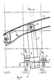
- a bumper for a vehicle includes one in the transverse direction of the vehicle extending bumper beam 2, on the in the event of a front impact of the vehicle Shock lies.
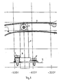
- Two energy-absorbing components 1 are between the bumper beam 2 and side members 12 (Fig. 3) of the vehicle and in the transverse direction of the vehicle at a distance arranged from each other. There is only one in the drawing Energy absorbing component 1 shown.
- the state without shows the adjacent shock are the energy absorbing components 1 at an angle to the longitudinal axis of the vehicle arranged at an angle to the outside.
- the sloping arrangement, that is the inclination angle is chosen so that the deviation X is the point 3 at which the energy-absorbing component 1 is connected to the bumper beam 2, from the parallel to the longitudinal axis of the vehicle, such as the expected shortening of the bumper beam 2 in the transverse direction when it bends due to an impact equivalent.
- energy-absorbing components 1 are provided, from a conical taper in the direction of impact Outer tube 9 and an inner tube 8 arranged therein, the inner dimensions of the outer tube 9 such are that the inner tube 8 is compressed and deformed if there is an impact from the Outer tube 9 is pressed through.
- the one achieved Deformation work leads to absorption by the shock transmitted impact energy.
- connection element of the energy absorbing component 1 to the longitudinal beam 12 is in the form of an angle plate 4 with a parallel frame part and an inclined part educated.
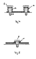
- the frame-parallel part of the angle plate 4 is in the manner shown in Fig. 4 with screws 6 with connected to the side member 12.
- the sloping part of the angle plate 4 is in the manner shown in Fig. 5 over a Screw 5 connected to the side member.
- the outside screws 6 have a threaded area 13 and an adjoining area with larger diameter 14. They are from an outer sleeve 10 surrounded, as shown in Fig. 4. On the one hand, they bring a preload and on the other hand are compliant, as soon as forces in the direction of the Longitudinal axis of the screw 6 occur. The screw 6 is attracted to the thickened area 14. In the angle plate 4 a hole is provided for this purpose, which has a diameter that is larger than the diameter of the region 14 is. The screw 6 is with its threaded portion 13 in the Screwed side member 12.
- the internal screw connection is similar to that external screw connection installed, it also shows only one provided under the head of the screw 5 Spring element 11, which is used for tolerance compensation.
- the bumper for a vehicle described above works for a shock on the bumper beam like follows:
Landscapes
- Engineering & Computer Science (AREA)
- Mechanical Engineering (AREA)
- Vibration Dampers (AREA)
- Vehicle Body Suspensions (AREA)
- Steering-Linkage Mechanisms And Four-Wheel Steering (AREA)
Claims (4)
- Pare-chocs pour un véhicule, comprenant un support de pare-chocs (2) qui s'étend dans le sens transversal du véhicule et deux éléments absorbant l'énergie (1), qui sont agencés entre le support de pare-chocs (2) et les longerons (12) du véhicule, dans le sens transversal du véhicule à distance l'un de l'autre et en formant un angle par rapport à l'axe longitudinal du véhicule en oblique vers l'extérieur au niveau des longerons (12), caractérisé en ce que le support de pare-chocs (2) est déformable et les éléments absorbant l'énergie (1) sont agencés par rapport à l'axe longitudinal du véhicule en formant un angle tel que les écarts (X) des points de montage (3) des éléments absorbant l'énergie (1) au niveau du support de pare-chocs (2) par rapport à un agencement des éléments absorbant l'énergie (1) parallèle à l'axe longitudinal du véhicule, correspondent au raccourcissement dans le sens transversal de la distance des points de montage (3) au niveau du support de pare-chocs (2), qui se produit lors d'une déformation du support de pare-chocs (2).
- Pare-chocs selon la revendication 1, caractérisé en ce qu'un élément d'assemblage des éléments absorbant l'énergie (1) contre le longeron (12) du véhicule est conçu sous la forme d'une plaque angulaire (4), dont la ligne de flexion forme un axe de basculement autour duquel les éléments absorbant l'énergie (1) peuvent basculer vers l'intérieur.
- Pare-chocs selon la revendication 2, caractérisé en ce que l'élément d'assemblage est vissé à l'extérieur et à l'intérieur contre le longeron (12) du véhicule.
- Pare-chocs selon la revendication 3, caractérisé en ce que l'assemblage vissé extérieur est formé par une vis (6) avec une zone filetée (13) et une zone (14) à plus grand diamètre, adjacente à celle-ci, autour de laquelle est prévue une gaine (10) et par laquelle la vis (6) est serrée contre l'élément d'assemblage.
Applications Claiming Priority (2)
| Application Number | Priority Date | Filing Date | Title |
|---|---|---|---|
| DE19822491A DE19822491B4 (de) | 1998-05-19 | 1998-05-19 | Stoßfänger für ein Fahrzeug |
| DE19822491 | 1998-05-19 |
Publications (3)
| Publication Number | Publication Date |
|---|---|
| EP0958968A2 EP0958968A2 (fr) | 1999-11-24 |
| EP0958968A3 EP0958968A3 (fr) | 2002-01-09 |
| EP0958968B1 true EP0958968B1 (fr) | 2003-12-17 |
Family
ID=7868311
Family Applications (1)
| Application Number | Title | Priority Date | Filing Date |
|---|---|---|---|
| EP99107906A Expired - Lifetime EP0958968B1 (fr) | 1998-05-19 | 1999-04-21 | Pare-chocs pour véhicule |
Country Status (3)
| Country | Link |
|---|---|
| EP (1) | EP0958968B1 (fr) |
| AT (1) | ATE256580T1 (fr) |
| DE (2) | DE19822491B4 (fr) |
Families Citing this family (4)
| Publication number | Priority date | Publication date | Assignee | Title |
|---|---|---|---|---|
| DE19906682B4 (de) * | 1999-02-18 | 2009-03-12 | Suspa Holding Gmbh | Schutzvorrichtung für Kraftfahrzeuge |
| DE19942059C2 (de) * | 1999-09-03 | 2003-11-27 | Audi Ag | Stoßfängeranordnung an einem Kraftfahrzeug |
| SE528073C2 (sv) * | 2004-03-08 | 2006-08-29 | Scania Cv Ab | Skyddsanordning för ett fordon |
| DE102005021661B4 (de) * | 2005-05-06 | 2007-10-04 | Benteler Automobiltechnik Gmbh | Crashbox |
Family Cites Families (12)
| Publication number | Priority date | Publication date | Assignee | Title |
|---|---|---|---|---|
| DE1933852A1 (de) * | 1969-07-03 | 1971-01-14 | Menasco Mfg Company | Stossdaempfungsvorrichtung |
| DE2127258C3 (de) * | 1971-06-02 | 1978-10-05 | Daimler-Benz Ag, 7000 Stuttgart | Anordnung einer Stoßstange an einem Fahrzeug, insbesondere an einem Kraftfahrzeug |
| DE2129526A1 (de) * | 1971-06-15 | 1972-12-21 | Volkswagenwerk Ag | Stossfaengeranordnung fuer ein Fahrzeug |
| DE2131054A1 (de) * | 1971-06-23 | 1973-01-11 | Volkswagenwerk Ag | Stossfaengeranordnung, insbesondere fuer kraftfahrzeuge |
| DE2131837A1 (de) * | 1971-06-26 | 1972-12-28 | Volkswagenwerk Ag | Stossfaengeranordnung,insbesondere fuer Kraftfahrzeuge |
| US3754784A (en) * | 1971-11-26 | 1973-08-28 | Gen Motors Corp | Vehicle bumper mounting arrangement |
| NO133790C (fr) * | 1972-03-14 | 1976-06-30 | Raufoss Ammunisjonsfabrikker | |
| GB1397455A (en) * | 1972-11-17 | 1975-06-11 | Imp Metal Ind Kynoch Ltd | Motor vehicles including energy absorbing systems |
| DE2336929A1 (de) * | 1973-07-20 | 1975-02-06 | Daimler Benz Ag | Fahrzeug mit einem in abschnitte unterschiedlicher gestaltfestigkeit unterteilten tragwerk |
| US4182529A (en) * | 1977-06-24 | 1980-01-08 | Tayco Developments, Inc. | Vehicle diverting energy absorber bumper system |
| AT395134B (de) * | 1990-11-16 | 1992-09-25 | Austria Metall | Pralldaempfer fuer kraftfahrzeuge |
| DE4238631C2 (de) * | 1992-11-16 | 2000-05-25 | Euromotive Gmbh | Verfahren zum Montieren einer Stoßverzehrvorrichtung |
-
1998
- 1998-05-19 DE DE19822491A patent/DE19822491B4/de not_active Expired - Fee Related
-
1999
- 1999-04-21 DE DE59908061T patent/DE59908061D1/de not_active Expired - Fee Related
- 1999-04-21 AT AT99107906T patent/ATE256580T1/de not_active IP Right Cessation
- 1999-04-21 EP EP99107906A patent/EP0958968B1/fr not_active Expired - Lifetime
Also Published As
| Publication number | Publication date |
|---|---|
| ATE256580T1 (de) | 2004-01-15 |
| EP0958968A3 (fr) | 2002-01-09 |
| EP0958968A2 (fr) | 1999-11-24 |
| DE19822491B4 (de) | 2005-04-28 |
| DE19822491A1 (de) | 1999-12-02 |
| DE59908061D1 (de) | 2004-01-29 |
Similar Documents
| Publication | Publication Date | Title |
|---|---|---|
| DE69814707T2 (de) | Stossenergie absorbierendes Element für ein Kraftfahrzeug | |
| EP0718158B1 (fr) | Pare-chocs pourvu de supports de fixation sur un véhicule | |
| DE2610001A1 (de) | Puffereinrichtung fuer fahrzeuge | |
| DE10130632A1 (de) | Fahrzeugsitz, insbesondere für ein minengeschütztes Kraftfahrzeug | |
| DE10308371A1 (de) | Sicherheitseinrichtung | |
| DE3544345A1 (de) | Kraftfahrzeuglenkung mit einer teleskoplenksaeule | |
| DE19911485B4 (de) | Vorrichtung zur schwenkbaren Unterstützung einer Lenksäule für eine Lenkradhöhenverstellvorrichtung | |
| EP0608531B1 (fr) | Attelage automatique à tampon central | |
| DE10358492A1 (de) | Crashelement in Form eines Hohlprofils | |
| DE102009032734A1 (de) | Crashstruktur für ein Kraftfahrzeug | |
| EP1057716B1 (fr) | Construction d'essieu pour véhicules utilitaires, leurs remorques et semi-remorques | |
| WO2007115950A1 (fr) | Dispositif de crashbox | |
| DE10028704A1 (de) | Kraftfahrzeug mit Aggregateabsenkung | |
| DE69115609T2 (de) | Lenksäule versehen mit einem energieabsorbierenden System | |
| DE102020210685B4 (de) | Montagehilfsvorrichtung und Verfahren zur Montage zweier Bauteile | |
| EP0958968A2 (fr) | Pare-chocs pour véhicule | |
| DE10260787B3 (de) | Vorrichtung zur Halterung eines Aggregats | |
| DE102017008542A1 (de) | Anfahrpuffer | |
| DE102023200676B3 (de) | Federbein, Montagesystem und Kraftfahrzeug | |
| EP1541459B1 (fr) | Unité de support pour le montage de plusieurs dispositifs extensibles sur un sous-marin | |
| DE202008007671U1 (de) | Vorderbau für ein Kraftfahrzeug | |
| DE10232799A1 (de) | Vorbaustruktur an Kraftfahrzeugen | |
| EP3971043B1 (fr) | Engin de travail agricole | |
| DE29823725U1 (de) | Stoßfänger für ein Fahrzeug | |
| DE102017007553A1 (de) | Kraftfahrzeug mit einer Versteifungsvorrichtung und Versteifungsvorrichtung für ein Kraftfahrzeug |
Legal Events
| Date | Code | Title | Description |
|---|---|---|---|
| PUAI | Public reference made under article 153(3) epc to a published international application that has entered the european phase |
Free format text: ORIGINAL CODE: 0009012 |
|
| AK | Designated contracting states |
Kind code of ref document: A2 Designated state(s): AT BE CH CY DE DK ES FI FR GB GR IE IT LI LU MC NL PT SE Kind code of ref document: A2 Designated state(s): AT DE FR GB IT SE |
|
| AX | Request for extension of the european patent |
Free format text: AL;LT;LV;MK;RO;SI |
|
| PUAL | Search report despatched |
Free format text: ORIGINAL CODE: 0009013 |
|
| AK | Designated contracting states |
Kind code of ref document: A3 Designated state(s): AT BE CH CY DE DK ES FI FR GB GR IE IT LI LU MC NL PT SE |
|
| AX | Request for extension of the european patent |
Free format text: AL;LT;LV;MK;RO;SI |
|
| 17P | Request for examination filed |
Effective date: 20020424 |
|
| 17Q | First examination report despatched |
Effective date: 20020710 |
|
| AKX | Designation fees paid |
Free format text: AT DE FR GB IT SE |
|
| GRAH | Despatch of communication of intention to grant a patent |
Free format text: ORIGINAL CODE: EPIDOS IGRA |
|
| GRAS | Grant fee paid |
Free format text: ORIGINAL CODE: EPIDOSNIGR3 |
|
| GRAA | (expected) grant |
Free format text: ORIGINAL CODE: 0009210 |
|
| AK | Designated contracting states |
Kind code of ref document: B1 Designated state(s): AT DE FR GB IT SE |
|
| REG | Reference to a national code |
Ref country code: GB Ref legal event code: FG4D Free format text: NOT ENGLISH |
|
| REG | Reference to a national code |
Ref country code: IE Ref legal event code: FG4D Free format text: GERMAN |
|
| REF | Corresponds to: |
Ref document number: 59908061 Country of ref document: DE Date of ref document: 20040129 Kind code of ref document: P |
|
| GBT | Gb: translation of ep patent filed (gb section 77(6)(a)/1977) |
Effective date: 20040211 |
|
| REG | Reference to a national code |
Ref country code: SE Ref legal event code: TRGR |
|
| RAP2 | Party data changed (patent owner data changed or rights of a patent transferred) |
Owner name: EUROMOTIVE GESELLSCHAFT M.B.H. & CO. KG |
|
| REG | Reference to a national code |
Ref country code: IE Ref legal event code: FD4D |
|
| ET | Fr: translation filed | ||
| PLBE | No opposition filed within time limit |
Free format text: ORIGINAL CODE: 0009261 |
|
| STAA | Information on the status of an ep patent application or granted ep patent |
Free format text: STATUS: NO OPPOSITION FILED WITHIN TIME LIMIT |
|
| 26N | No opposition filed |
Effective date: 20040920 |
|
| PG25 | Lapsed in a contracting state [announced via postgrant information from national office to epo] |
Ref country code: IT Free format text: LAPSE BECAUSE OF NON-PAYMENT OF DUE FEES Effective date: 20050421 |
|
| PGFP | Annual fee paid to national office [announced via postgrant information from national office to epo] |
Ref country code: AT Payment date: 20070412 Year of fee payment: 9 |
|
| PGFP | Annual fee paid to national office [announced via postgrant information from national office to epo] |
Ref country code: SE Payment date: 20070413 Year of fee payment: 9 |
|
| PGFP | Annual fee paid to national office [announced via postgrant information from national office to epo] |
Ref country code: DE Payment date: 20070430 Year of fee payment: 9 |
|
| PGFP | Annual fee paid to national office [announced via postgrant information from national office to epo] |
Ref country code: GB Payment date: 20070412 Year of fee payment: 9 |
|
| PGFP | Annual fee paid to national office [announced via postgrant information from national office to epo] |
Ref country code: FR Payment date: 20070413 Year of fee payment: 9 |
|
| EUG | Se: european patent has lapsed | ||
| GBPC | Gb: european patent ceased through non-payment of renewal fee |
Effective date: 20080421 |
|
| PG25 | Lapsed in a contracting state [announced via postgrant information from national office to epo] |
Ref country code: DE Free format text: LAPSE BECAUSE OF NON-PAYMENT OF DUE FEES Effective date: 20081101 |
|
| REG | Reference to a national code |
Ref country code: FR Ref legal event code: ST Effective date: 20081231 |
|
| PG25 | Lapsed in a contracting state [announced via postgrant information from national office to epo] |
Ref country code: AT Free format text: LAPSE BECAUSE OF NON-PAYMENT OF DUE FEES Effective date: 20080421 |
|
| PG25 | Lapsed in a contracting state [announced via postgrant information from national office to epo] |
Ref country code: FR Free format text: LAPSE BECAUSE OF NON-PAYMENT OF DUE FEES Effective date: 20080430 |
|
| PG25 | Lapsed in a contracting state [announced via postgrant information from national office to epo] |
Ref country code: GB Free format text: LAPSE BECAUSE OF NON-PAYMENT OF DUE FEES Effective date: 20080421 |
|
| PGFP | Annual fee paid to national office [announced via postgrant information from national office to epo] |
Ref country code: IT Payment date: 20070619 Year of fee payment: 9 |
|
| PGRI | Patent reinstated in contracting state [announced from national office to epo] |
Ref country code: IT Effective date: 20091201 |
|
| PG25 | Lapsed in a contracting state [announced via postgrant information from national office to epo] |
Ref country code: SE Free format text: LAPSE BECAUSE OF NON-PAYMENT OF DUE FEES Effective date: 20080422 |
|
| PGRI | Patent reinstated in contracting state [announced from national office to epo] |
Ref country code: IT Effective date: 20091201 |