EP0959008A1 - Machine modulaire de fabrication - Google Patents
Machine modulaire de fabrication Download PDFInfo
- Publication number
- EP0959008A1 EP0959008A1 EP99109728A EP99109728A EP0959008A1 EP 0959008 A1 EP0959008 A1 EP 0959008A1 EP 99109728 A EP99109728 A EP 99109728A EP 99109728 A EP99109728 A EP 99109728A EP 0959008 A1 EP0959008 A1 EP 0959008A1
- Authority
- EP
- European Patent Office
- Prior art keywords
- frame
- shape
- modules
- fact
- channel
- Prior art date
- Legal status (The legal status is an assumption and is not a legal conclusion. Google has not performed a legal analysis and makes no representation as to the accuracy of the status listed.)
- Withdrawn
Links
- 238000004519 manufacturing process Methods 0.000 title claims abstract description 9
- 230000008878 coupling Effects 0.000 claims abstract description 8
- 238000010168 coupling process Methods 0.000 claims abstract description 8
- 238000005859 coupling reaction Methods 0.000 claims abstract description 8
- 238000004806 packaging method and process Methods 0.000 claims abstract description 7
- 238000009434 installation Methods 0.000 claims abstract description 5
- 241000208125 Nicotiana Species 0.000 claims abstract description 4
- 235000002637 Nicotiana tabacum Nutrition 0.000 claims abstract description 4
- 235000019504 cigarettes Nutrition 0.000 claims abstract description 4
- 230000004224 protection Effects 0.000 claims description 12
- 230000005540 biological transmission Effects 0.000 claims description 7
- 230000007246 mechanism Effects 0.000 claims description 5
- 239000012530 fluid Substances 0.000 claims description 2
- 238000012216 screening Methods 0.000 claims 1
- 230000033001 locomotion Effects 0.000 description 8
- 238000010276 construction Methods 0.000 description 3
- 230000008901 benefit Effects 0.000 description 2
- 239000006096 absorbing agent Substances 0.000 description 1
- 230000001419 dependent effect Effects 0.000 description 1
- 230000035939 shock Effects 0.000 description 1
- 239000000126 substance Substances 0.000 description 1
Images



Classifications
-
- B—PERFORMING OPERATIONS; TRANSPORTING
- B65—CONVEYING; PACKING; STORING; HANDLING THIN OR FILAMENTARY MATERIAL
- B65B—MACHINES, APPARATUS OR DEVICES FOR, OR METHODS OF, PACKAGING ARTICLES OR MATERIALS; UNPACKING
- B65B59/00—Arrangements to enable machines to handle articles of different sizes, to produce packages of different sizes, to vary the contents of packages, to handle different types of packaging material, or to give access for cleaning or maintenance purposes
- B65B59/04—Machines constructed with readily-detachable units or assemblies, e.g. to facilitate maintenance
Definitions
- the invention relates to a manufacturing machine, in particular a machine for the processing of tobacco or for the packaging of cigarettes or similar, of the modular type.
- the aim of the invention is the one to create a machine of the above-mentioned type with features of modularity such that take into consideration diverse operational units that are foreseen in the same machine allowing for a subdivision in modules according to a logic that covers at least in substance the operational plans and that allow to load the manufacturing machine with ease into containers, allowing to minimize the number of the same thanks thanks to a better use of the loading volume available.
- the invention aims at obtaining the above-mentioned purposes thanks to a modular construction that at the same time makes the manufacture and assembly of the machine less costly and more flexible.
- the invention aims at perfectioning this type of construction.
- the invention attains the above-mentioned purposes with a manufacturing machine of the type described at the beginning in which the bed is formed by a plurality of modular support frames made in shape of a table with dimensions substantially equal or of the same order of magnitude and that can be fixed in a movable manner to each other, while a plurality of operating, control, drive and supply and guide units for the feeding and control installations are provided that are made in form of modular prefabricated units and that have couplings prearranged to mate with coupling means these also prearranged on modular support structures.
- Each modular support structure in form of a table is associated with preset modular prefabricated units that can be at least for the majority of the said modular units assembled beforehand on their corresponding modules in their substantially final position before the positioning and coupling of the frame modules to each other, the operating units being connected to one other and supported by adjacent frame modules in form of a table positioned in the correct working position, so that upon the relative positioning and connection of the framework modules to each other the operating units come to be in their relative substantially correct working position, with exception for possible positioning tolerances. These will have to be eventually corrected during the phase of assembly to each of the individual modular frameworks in shape of a table.
- the dimensions of the individual framework modules equipped with the modular units fitted on the same are commensurate to the volumetrics of the containers, in order to be able to house the maximum possible number of the said frame modules with the pre-assembled modular units in the smallest number of containers.
- the machine is equipped with at least one channel for housing the cables, conduits or other link-up parts of the supply , control installations and of other type that extends itself in direction of the longitudinal extension of the machine and that at least one channel is made in modular segments each of which is connected to a modular framework in shape of a table, as the individual channel segments can be connected in a movable manner to each other upon their assembly to each other of the bed frame modules in shape of a table.
- the channel is made in form of a longitdinal tubular part suspended in the rear top section of the total dimension in height of the machine, each segment of the channel being supported by a pair of vertical risers connected on the sides of the frame modules in shape of a table of reciprocal connection and on the end sides of the external modules.
- the channel extends itself along the entire rear side of the machine, wuile a cabinet containing the control and drive modules is provided that is also modular and with a longitudinal extension parallel to the one of the framework in shape of a table in the assembled condition.
- the cables and conduits and the other lines of supply, control and for the execution of sending or the transmission and reception of other signals or fluids advantageously branch out from a distribution module that is foreseen in a segment of a channel connected to an intermediate framework module in shape of a table.
- the distribution box itself is formed by said segment of channel from which depart the branching conduits to the cabinet.
- the housing of the cables, conduits or other supply, control lines, etc. is foreseen in the disassembled condition of the individual framework modules in shape of a table and that is formed by the distribution segment of the guide channel of the conduits, the cables and of the lines, and inside of which during transport are folded in the sections of the cables, of the conduits and other lines designed to run in the additional segments of the channel associated with the additional modules of the frame in shape of a table to connect themselves to the modular units assembled on the same.
- the machine has a framework for the protection screens and parts or for possible other guards that is itself also made in a modular manner, the individual modules being subdivided correspondingly to the frame modules in shape of a table, analogous to the channel for the cabels and conduits.
- each framework module in form of a table has a support frame for the screens, the guards or similar means of protection and that the support frames of said screens or similar of protection and/or the screens themselves modularly complete each other, in the assembled condition one to the other of the frame modules in shape a table.
- Each modular support frame of the protection screens or similar associated with each modular framework in shape of a table has furthermore its own hinged means to move into open or closed position part of the screens, or similar in shape of a wing or door.
- the protection screens or similar are made in the shape of a part suspended projecting on the frame in shape of a table and have such a span as to cover the top side and the service one on the front associated with the corresponding frame module in shape of a table.
- each screen associated with each modular frame in shape of a table is made with transversal sections substantially in shape of an L with a substantially horizontal top branch and a front branch substantially vertical that join together in a rounded manner, while the free end of the top horizontal branch is hinged to a mechanism of articulation supported by a segment of a beam substantially parallel to the segment of the channel for the cables and conduits and the lines or to the said segment of the channel itself.
- the mechanism of articulation furthermore is formed in shape of an articulated parallelogram of such dimensions, that the lifting of the screen from the closed position to the open one takes place substantially in the vertical direction, or else substantially parallel to the vertical branch of the said screen for a section corresponding to the mean height of a human being, while in the remaining part it also move additonally transversally rearward to also free the top part of the units associated with the corresponding modular frame in shape of a table.
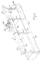
- a machine according to the invention in particular a machine for processing tobacco and more specifically a machine for packaging of cigarettes has a support bed of the individual operating units made in form of a table 1.
- This frame in shape of a table 1 is of the type as for example described in the patent EP816714 of the same holder.
- the operating units, the transmission units and the drive units are realized prefabricated each in shape of an independent modular assembly with its own support frame or box, that is provided with prearranged mounting means to, on or in housings of the frame in shape of a table.
- the modular operating, transmission and drive units are not illustrated in detail, as these are not part of the present invention.
- the frame in shape of a table is instead subdivided into individual modular sections 101, 201, 301.
- the subdivisions are made transversally to the longitudinal extension of the machine, but this is only an example and does not constitute a limiting feature, as according to the topology of the machine it is possible to foresee also other types of subdivisions.
- Each module 101, 201, 301, of the framework in shape of a table is therefore designed to be secured in a movable manner to the adjacent module.
- the clamping can be made thanks to any means as screw type means and can be provided also with truing means such as truing dowels cooperating with truing holes, eventually the dowels and holes being partially conical and provided with automatic truing surfaces such as inclined planes, or similar.
- the lines of subdivision between the individual modules 101, 201, 301 of the frame in shape of a table 1 are preferably made in such a manner to allow the assembly on said module of the major part of the modular operating, transmission and supply units and eventually also following a certain logic of the manufacturing process the machine has to carry out. Furthermore, the subdivisions between the modules 101, 201, 301 of the frame in shape of a table are chosen in such a manner, that the dimensions of the same are suited to the dimensions of the loading volume of the containers, in that it is possible to load the machine in the smallest number of containers possible and to exploit in full the volumetric load capacity.
- each module 101, 201, 301 of the frame in shape of a table 1 can be prefabricated in the factory of the major part of the modular operating, transmission and drive units and can find place in a container as a placement and loading of the same is possible independently from the remaining modules of the frame in shape of a table.
- the standard dimensions in height and width of the different packagings for the different means of the transport are in the order of magnitude of approximately 200 cm to approximately 240 cm, while in order to allow a sufficent ease of handling the packagings can not exceed 500 cm in lentgh.
- the packagings can not exceed 500 cm in lentgh.
- the machine according to the invention has at least one channel, in particular two channels of distribution of the cables, conduits or other lines of supply, control or for other functions.
- This channel or channels 2, 3 extend themselves advantageously in a position of non interference and in a preferential manner along the rear longitudinal side of the machine, especially in an upper position, or in any case in the area of the maximium top dimensions of the machine.
- the distribution channels 2, 3, are supported in this case by risers 4 that are provided in pairs on the opposite end sides of each module 101, 201, 301 of the frame in shape of a table 1. Therefore adjacent modules 101, 201, 301 have also adjacent risers 4.
- the risers 4 on the adjacent end sides of reciprocal clamping of the modules of the frame in shape of a table 101, 201, 301, are furthermore made in such a manner to form together one column.
- the distribution channels 2, 3 are themselves also made modular as they are formed by individual segments 102, 103, 202, 203, 302, 303 of a length corresponding to the dimensions of the associated module 101, 201, 301 of the frame in shape of a table 1. Therefore each module of the frame in shape of a table 101, 201, 301 has preassembled on the same in addition to the modular operating units of transmission and of drive also its own section of the channel or channels of distribution.
- the branchings 402, 403 from the channel or channels 2, 3 to a cabinet containing the control electronics and other drive and control units, as well as eventually the generators are provided in correspondence to one of the modular segments 202, 203 of the channels 2, 3, preferably in correpondence to a modular segment of the channel 202, 302 associated with a module 201 of the frame in shape of a table in intermediate position.
- the volume of the internal space of the channels or in particular eventually only of the segments 202, 302 equipped with the branchings 402, 403 is such to house in disassembled condition of the modules 101, 201, 301 of the frame in shape of a table 1 and therefore of the segments of the channel 102, 202, 302, 103, 203, 303 in a position folded back on themselves also the cables and the eventual control supply lines and/or for other purposes that in the assembled condition of the channels 2, 3 extend themselves into the segments 102, 302, 103, 303 of the modules 101, 301 of the frame 1 in shape of a table adjacent to the intermediate one 201 of which the channel segments 202, 302 have the branchings 402, 403.
- a movable cover 6 is fixed to a longitudinal beam that is substantially segmented corresponding to the modular segments of the channel 2, 3 and is parrallel to the channel or channels 2, 3 itself and substantially extends itself at the level of said channels, or is advantageously formed by the same channels 2, 3. Also this cover 6 is made modular, or rather is formed by individual covering segments that complete each other in order to form a single cover and that are divided between each other in a manner corresponding to the modules 101, 201, 301 of the frame in shape of a table 1. Each module 101, 201, 301 of the frame in shape of a table 1 has therefore its own cover section 205. This one can also be fixed beforehand to the corresponding part of the beam of the channel 201, 301, 202, 302, 103, 303, before the recripocal assembly of the modules 101, 201, 301 of the frame in shape of a table 1.
- the said cover 5 and the corresponding modules are made in a shape substantially in form of an L with a branch 305 substantially horizontal and on top that covers the machine on the top and a vertical branch 405 that covers the front part and that can extend itself up to the edge of the plane of the modules 101, 201, 301 of the frame in shape of a table 1 or if necessary down to the floor.
- the segment of the cover preferably the entire cover segment is fixed to the corresponding segment of the beam or channel 103, 203, 303, in an upwards turnable manner.
- the cover segments 205 are supported projecting from the front side of the segment of the beam or of the channel 103, 203, 303 and are articulated in an oscillating manner around a horizontal axis.
- the cover segments 205 do not exceed the total dimension in height defined by the top side of the channel 2, 3.
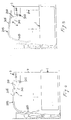
- the cover segments 205 are further articulated projecting on the front side of the segment of the beam or of the modular segment of the channel 103, 203, 303 thanks to a device of articulation in form of an articulated parallelogram overall indicated with 7 and that has a mounting plate 107 carried projecting by a pair of arms of articulation 207, 307 provided on each head of the plate and articulated respectively in correspondence to the front edge and the rear one of the said plate 107, while the opposite extremities of the arms 207, 307 are articulated in vertically distanced points 407, 507 on the front side of the corresponding segment of the beam of the channel 103, 203, 303.
- the motion of opening and closing can be obtained in different ways, for example by means of linear actuators 8 positioned as indicated in Fig. 3 and that act between the plane of the corresponding module 101, 201, 301 of the frame in shape of a table 1 and the horizontal internal branch of the cover segment 205 or thanks to motors that drive one of the axis of articulation of the device of articulation 7. It is possible to also provide opening and closing shock absorbers.
- the mounting plate 107 extends itself for substantially the entire length of the cover segment 205 and is substantially horizontal in the position of closure of the cover 5.
- the cover segments 205 can be mounted in a movable manner on the said plate 107 in any which way.
- a transversal section of a module 101, 201, 301 of the frame in shape of a table 1 is illustrated, with the columns 4, the channel 2, 3 or a generic beam and with the corresponding cover module 205.
- the total dimension in height of the machine is calibrated on the mean height of a man with his arm raised and furthermore, the fulcra of the device of articulation 7 are illustrated and with dotted lines the arms 207, 307 of the same.
- the length of the arms and the position of the fulcra is such, that during the upward angular movement of the cover module 205, the vertical branch of the same carries out at least for part of the motion a movement substantially rectilinear or vertical or in any case substantially parallel to itself, or with a very much reduced component of movement outward in the direction of the front of the machine.
- the outward movement takes place only and in a limited dimension at the end part of the angular motion in direction of opening of the cover segment 205.
- the long section of the free bottom edge of the cover segments 205 is slighty folded back inward for a certain length of the vertical extension of said vertical branch of the cover 5. This type of opening motion of the cover 5, allows to limit the dimension required by the machine, as well as to avoid danger for the servicing personnel.
Landscapes
- Engineering & Computer Science (AREA)
- Mechanical Engineering (AREA)
- Accommodation For Nursing Or Treatment Tables (AREA)
- Catching Or Destruction (AREA)
- Lighting Device Outwards From Vehicle And Optical Signal (AREA)
- Switches With Compound Operations (AREA)
Applications Claiming Priority (2)
| Application Number | Priority Date | Filing Date | Title |
|---|---|---|---|
| ITSV980033 | 1998-05-22 | ||
| IT1998SV000033A IT1305963B1 (it) | 1998-05-22 | 1998-05-22 | Macchina operatrice modulare. |
Publications (1)
| Publication Number | Publication Date |
|---|---|
| EP0959008A1 true EP0959008A1 (fr) | 1999-11-24 |
Family
ID=11408285
Family Applications (1)
| Application Number | Title | Priority Date | Filing Date |
|---|---|---|---|
| EP99109728A Withdrawn EP0959008A1 (fr) | 1998-05-22 | 1999-05-18 | Machine modulaire de fabrication |
Country Status (2)
| Country | Link |
|---|---|
| EP (1) | EP0959008A1 (fr) |
| IT (1) | IT1305963B1 (fr) |
Cited By (9)
| Publication number | Priority date | Publication date | Assignee | Title |
|---|---|---|---|---|
| EP1149769A3 (fr) * | 2000-04-25 | 2002-01-16 | Focke & Co. (GmbH & Co.) | Machine, en particulier une machine d' emballage (de cigarettes) |
| WO2002051706A1 (fr) * | 2000-12-22 | 2002-07-04 | Aautomag S.R.L. | Systeme modulaire constitue par une construction de profiles en acier pour chaine d'emballage |
| EP1532873A3 (fr) * | 2003-11-21 | 2005-08-03 | G.D Societ Per Azioni | Machine automatique pour manipuler des articles à tabac |
| DE102004044846A1 (de) * | 2004-09-10 | 2006-03-16 | Optima Filling And Packaging Machines Gmbh | Anlage zum Abfüllen |
| WO2007090653A1 (fr) * | 2006-02-09 | 2007-08-16 | Cfs Germany Gmbh | Emballeuse dotee d'un cadre |
| DE102007017646A1 (de) * | 2007-04-13 | 2008-10-16 | Iwk Verpackungstechnik Gmbh | Verpackungsmaschine |
| EP1920668A3 (fr) * | 2006-11-13 | 2009-09-02 | Hauni Maschinenbau AG | Dispositif de stockage et procédé destiné à éviter une pression locale dans un dispositif de stockage |
| DE102015001311A1 (de) * | 2015-02-05 | 2016-08-11 | Focke & Co. (Gmbh & Co. Kg) | Modulare Vorrichtung zum Herstellen von Packungen mit einer Gruppe von Zigaretten als Packungsinhalt |
| DE102016214417A1 (de) * | 2016-08-04 | 2018-02-08 | Multivac Sepp Haggenmüller Se & Co. Kg | Verpackungsmaschine mit Haltevorrichtung für Schutzabdeckung |
Citations (7)
| Publication number | Priority date | Publication date | Assignee | Title |
|---|---|---|---|---|
| DE2728759A1 (de) * | 1977-06-25 | 1979-01-18 | Benz & Hilgers Gmbh | Maschinenanlage zum vereinzeln und zum fuellen und verschliessen von becherfoermigen behaeltern |
| US4569180A (en) * | 1984-03-02 | 1986-02-11 | Luigi Russo | System for reversing the sequential position of the operative units in automatic packaging machinery |
| EP0294251A1 (fr) * | 1987-05-12 | 1988-12-07 | Cmb Remy | Machine de conditionnement automatique de récipients |
| DE4131800A1 (de) * | 1991-09-24 | 1993-03-25 | Krempel August Soehne | Verpackungsmaschine |
| EP0645307A1 (fr) * | 1993-09-27 | 1995-03-29 | Focke & Co. (GmbH & Co.) | Machine d'emballage pour la production de paquets de cigarettes |
| EP0756996A1 (fr) * | 1995-08-02 | 1997-02-05 | SASIB S.p.A. | Machine de traitement, spécialement machine d'emballage de cigarettes ou similaires |
| EP0826602A1 (fr) * | 1996-07-31 | 1998-03-04 | Gerhard Schubert GmbH | Machine d'emballage modulaire |
-
1998
- 1998-05-22 IT IT1998SV000033A patent/IT1305963B1/it active
-
1999
- 1999-05-18 EP EP99109728A patent/EP0959008A1/fr not_active Withdrawn
Patent Citations (7)
| Publication number | Priority date | Publication date | Assignee | Title |
|---|---|---|---|---|
| DE2728759A1 (de) * | 1977-06-25 | 1979-01-18 | Benz & Hilgers Gmbh | Maschinenanlage zum vereinzeln und zum fuellen und verschliessen von becherfoermigen behaeltern |
| US4569180A (en) * | 1984-03-02 | 1986-02-11 | Luigi Russo | System for reversing the sequential position of the operative units in automatic packaging machinery |
| EP0294251A1 (fr) * | 1987-05-12 | 1988-12-07 | Cmb Remy | Machine de conditionnement automatique de récipients |
| DE4131800A1 (de) * | 1991-09-24 | 1993-03-25 | Krempel August Soehne | Verpackungsmaschine |
| EP0645307A1 (fr) * | 1993-09-27 | 1995-03-29 | Focke & Co. (GmbH & Co.) | Machine d'emballage pour la production de paquets de cigarettes |
| EP0756996A1 (fr) * | 1995-08-02 | 1997-02-05 | SASIB S.p.A. | Machine de traitement, spécialement machine d'emballage de cigarettes ou similaires |
| EP0826602A1 (fr) * | 1996-07-31 | 1998-03-04 | Gerhard Schubert GmbH | Machine d'emballage modulaire |
Cited By (11)
| Publication number | Priority date | Publication date | Assignee | Title |
|---|---|---|---|---|
| EP1149769A3 (fr) * | 2000-04-25 | 2002-01-16 | Focke & Co. (GmbH & Co.) | Machine, en particulier une machine d' emballage (de cigarettes) |
| WO2002051706A1 (fr) * | 2000-12-22 | 2002-07-04 | Aautomag S.R.L. | Systeme modulaire constitue par une construction de profiles en acier pour chaine d'emballage |
| EP1532873A3 (fr) * | 2003-11-21 | 2005-08-03 | G.D Societ Per Azioni | Machine automatique pour manipuler des articles à tabac |
| US7509960B2 (en) | 2003-11-21 | 2009-03-31 | D Societa′ per Azioni | Automatic machine for processing tobacco articles |
| DE102004044846A1 (de) * | 2004-09-10 | 2006-03-16 | Optima Filling And Packaging Machines Gmbh | Anlage zum Abfüllen |
| DE102004044846B4 (de) * | 2004-09-10 | 2015-05-28 | Optima consumer GmbH | Anlage zum Abfüllen |
| WO2007090653A1 (fr) * | 2006-02-09 | 2007-08-16 | Cfs Germany Gmbh | Emballeuse dotee d'un cadre |
| EP1920668A3 (fr) * | 2006-11-13 | 2009-09-02 | Hauni Maschinenbau AG | Dispositif de stockage et procédé destiné à éviter une pression locale dans un dispositif de stockage |
| DE102007017646A1 (de) * | 2007-04-13 | 2008-10-16 | Iwk Verpackungstechnik Gmbh | Verpackungsmaschine |
| DE102015001311A1 (de) * | 2015-02-05 | 2016-08-11 | Focke & Co. (Gmbh & Co. Kg) | Modulare Vorrichtung zum Herstellen von Packungen mit einer Gruppe von Zigaretten als Packungsinhalt |
| DE102016214417A1 (de) * | 2016-08-04 | 2018-02-08 | Multivac Sepp Haggenmüller Se & Co. Kg | Verpackungsmaschine mit Haltevorrichtung für Schutzabdeckung |
Also Published As
| Publication number | Publication date |
|---|---|
| IT1305963B1 (it) | 2001-05-21 |
| ITSV980033A1 (it) | 1999-11-22 |
| ITSV980033A0 (it) | 1998-05-22 |
Similar Documents
| Publication | Publication Date | Title |
|---|---|---|
| EP0959008A1 (fr) | Machine modulaire de fabrication | |
| ES2311782T3 (es) | Soporte formador para maquinas de envasado. | |
| JP3605183B2 (ja) | 手術台患者支持手段 | |
| CA2275718C (fr) | Dispositif de maniement d'objets | |
| US4998702A (en) | Suspension apparatus for control device | |
| CN109279090A (zh) | 一种用于平板电视包装的辅助设备和方法 | |
| CN105825733B (zh) | 一种多功能升降式焊接实训台 | |
| CA2296335C (fr) | Mecanisme d'entrainement pour barriere | |
| US6457574B1 (en) | Device for handling at least one tensioning frame, especially for mounting vehicle shells | |
| CA2224741A1 (fr) | Machine de conditionnement comportant une chambre definie par une partie superieure et une partie inferieure | |
| US7469460B2 (en) | Base framework for a manipulating apparatus and manipulating apparatus | |
| GB2222888B (en) | Filling containers | |
| IT202000016717A1 (it) | Unita' di alimentazione di sbozzati per una macchina impacchettatrice e provvista di un elemento di riferimento di posizione | |
| CA2927845A1 (fr) | Structure de soutien destinee a des machines de conditionnement | |
| EP2830827B1 (fr) | Couvercle de protection télescopique | |
| CN115764682A (zh) | 一种用于电力施工的电力设备 | |
| KR20220085013A (ko) | 패키징 플랜트 | |
| EP0628480B1 (fr) | Machine d'emballage ajustable | |
| US6105754A (en) | Transfer for machine tools | |
| US7179043B2 (en) | Manipulating arrangement and cell | |
| CN109357132A (zh) | 控制台及控制台支撑结构 | |
| CN115733056A (zh) | 一种配电柜 | |
| EP0994033B1 (fr) | Machine modulaire de fabrication | |
| CN215658394U (zh) | 一种动母线焊接设备 | |
| EP4570221B1 (fr) | Chaîne de production pour la fabrication de produits sanitaires tels que des produits absorbants à usage sanitaire |
Legal Events
| Date | Code | Title | Description |
|---|---|---|---|
| PUAI | Public reference made under article 153(3) epc to a published international application that has entered the european phase |
Free format text: ORIGINAL CODE: 0009012 |
|
| AK | Designated contracting states |
Kind code of ref document: A1 Designated state(s): DE FR GB |
|
| AX | Request for extension of the european patent |
Free format text: AL;LT;LV;MK;RO;SI |
|
| 17P | Request for examination filed |
Effective date: 20000503 |
|
| AKX | Designation fees paid |
Free format text: DE FR GB |
|
| RAP1 | Party data changed (applicant data changed or rights of an application transferred) |
Owner name: SASIB S.P.A. |
|
| 17Q | First examination report despatched |
Effective date: 20030321 |
|
| GRAP | Despatch of communication of intention to grant a patent |
Free format text: ORIGINAL CODE: EPIDOSNIGR1 |
|
| RIN1 | Information on inventor provided before grant (corrected) |
Inventor name: SPADA, VALTER |
|
| STAA | Information on the status of an ep patent application or granted ep patent |
Free format text: STATUS: THE APPLICATION IS DEEMED TO BE WITHDRAWN |
|
| 18D | Application deemed to be withdrawn |
Effective date: 20040818 |