EP0959025A1 - Convoyeur à la sortie d'une presse d'extrusion - Google Patents
Convoyeur à la sortie d'une presse d'extrusion Download PDFInfo
- Publication number
- EP0959025A1 EP0959025A1 EP98109182A EP98109182A EP0959025A1 EP 0959025 A1 EP0959025 A1 EP 0959025A1 EP 98109182 A EP98109182 A EP 98109182A EP 98109182 A EP98109182 A EP 98109182A EP 0959025 A1 EP0959025 A1 EP 0959025A1
- Authority
- EP
- European Patent Office
- Prior art keywords
- longitudinal
- conveyors
- conveyor
- toothed
- transverse
- Prior art date
- Legal status (The legal status is an assumption and is not a legal conclusion. Google has not performed a legal analysis and makes no representation as to the accuracy of the status listed.)
- Withdrawn
Links
Images

Classifications
-
- B—PERFORMING OPERATIONS; TRANSPORTING
- B21—MECHANICAL METAL-WORKING WITHOUT ESSENTIALLY REMOVING MATERIAL; PUNCHING METAL
- B21C—MANUFACTURE OF METAL SHEETS, WIRE, RODS, TUBES, PROFILES OR LIKE SEMI-MANUFACTURED PRODUCTS OTHERWISE THAN BY ROLLING; AUXILIARY OPERATIONS USED IN CONNECTION WITH METAL-WORKING WITHOUT ESSENTIALLY REMOVING MATERIAL
- B21C35/00—Removing work or waste from extruding presses; Drawing-off extruded work; Cleaning dies, ducts, containers, or mandrels for metal extruding
- B21C35/02—Removing or drawing-off work
Definitions
- the conveying devices arranged in the outlet of extrusion presses have the task the extruded strands in the pressing direction, i.e. Discharge direction along and then convey them in their entire length or in sections transversely to the Give strands or strand sections time to cool and if necessary a stretching bench and facilities for other post-treatment, for Allocate to commercial lengths and stackers. It is too ensure that the strand ends under slight tension, so that the strand is straight is kept stretched, which is why the longitudinal conveyor in the outlet at a conveying speed is operated, which is slightly larger than the pressing speed. This initially eliminates the need for special pull-out devices consisting of a carriage that can be moved along the outlet with grippers for the strand. Of the The structural effort of these pull-out devices cannot be compensated for by a less expensive training of the longitudinal conveyor, but it results in Need to coordinate longitudinal conveyor and pull-out device.
- Plate conveyors (DE-B2 13 00 898, DE-C2 25 56 894) are used as longitudinal conveyors, Beam straps (DE-C2 39 36 177) or belt straps used when the material to be pressed to protect the surface, do not push it sideways onto the cross conveyor, but instead to be removed, require a corresponding design by Belt deflections on the model of US Pat. No. 1,980,261, but preferably in the Form that individual belts one behind the other in a the distance of the cross conveyor appropriate length (DE-C2 39 36 177) can be used.
- the object of the invention is to simplify the construction with appropriate Achieve cost reduction and increased service life of the longitudinal conveyor belts.
- This problem is solved in that the longitudinal conveyor than by two Toothed drum guided toothed belts are formed, which - as with belt straps known - on the outside with a heat-resistant, the surface of the pressed material gentle fiber fleece pad and between the toothed drums by Slideways are supported.
- the positive connection between the toothed drums and Toothed belt results in a slip-free regardless of the tension of the toothed belt Power transmission for which only one drive, namely the one pulling the upper run Dental drum is sufficient.
- the second toothed drum, which is not driven, is only for Setting the center distance of the toothed drums, but not for the tension of the Timing belt adjustable.
- the timing belts are covered by steel strands or Glass fiber strands of great length constancy and highly resilient.
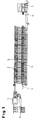
- Fig. 1 The entire system shown in Fig. 1 consists of an extrusion press 1 in the Spout a longitudinal conveyor 2 is arranged in the conveyor elements of a cross conveyor 3 intervene.
- the cross conveyor 3 takes over from the longitudinal conveyor 2 from the Extruder 1 pulled strands or sections of these strands through vertical relative movement of the longitudinal conveyor 2 and cross conveyor 3. During the The strands or rod sections find sufficient time at the transverse conveying cooling already beginning on the longitudinal conveyor 2.
- Integrated in the Cross conveyor 3 is a stretching bench 4 for stretching according to the embodiment of the strands or strand sections. From the cross conveyor 3, the strands or strand sections to another longitudinal conveyor 5, which they in Groups collected a saw or scissors 5 fed the strands in Distributes trading lengths and feeds a stacking device 7.
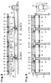
- the longitudinal conveyor 2 consists of a plurality cooperating single conveyor 12, each of which has a length that fills the gap closes between two adjacent conveyor elements 13 to the cross conveyor 3.
- everyone Single conveyor 12 consists of a frame 14 in which two toothed drums 15 and 16 are mounted, of which the toothed drum 15 via a bevel gear drive 17, 18th is driven by a shaft 19 while the toothed drum 16 is at a distance from it Toothed drum 15 is adjustable.
- the shafts 19 mounted in the frame 14 are interconnected by couplings 20 and by one, not shown Motor driven.
- a toothed belt 21 is guided around the toothed drums 15/16 of each frame 14, which is driven by the toothed drum 15.
- the toothed belt 21 consists of abrasion-resistant plastic, for example polyurethane and is reinforced with tensile strands 22 made of steel strands or fiberglass strands that the Give timing belt 21 a large length constancy.
- the outside or top is the Toothed belt 21 is provided with a non-woven pad 23, which is made of heat-resistant Fiber material. for example M-aramid fibers (heat resistance up to 550 ° C) exists and is glued to the toothed belt 21.
- the non-woven pad 23 protects the toothed belt 21 from excessive heating and the surface of the material to be pressed from damage.
- the side walls of the frame 14 carry slideways 24 of which the upper dreams the toothed belt 21 are supported between en toothed drums 15 and 16.
- the abrasion-resistant toothed belts 21 slide on the slideways 24.
- the conveyor elements 13 of the cross conveyor 3 protrude between the individual conveyors 12, so that by vertical relative movement between the conveyor elements 13 and to the individual conveyors 12, the strands that have run onto the individual conveyors 12 or Strand sections from the conveyor elements 13 for transverse transport on the Cross conveyor 3 can be taken over.
- On the foundation 27 are Columns 28 attached to the or the base frame 25 in the vertical direction lead flexibly.
- a base frame 25 is supported by toggle levers 29, whose one lever part 29a is variable in length for aligning the base frame 25 and for setting the formed by the upper edges of the toothed belt 21 Conveying plane of the longitudinal conveyor 2 to the conveying plane of the conveying elements 13 of the Cross conveyor 3.
- the other lever part 29b is connected to a lever 30.
- Die Levers 30 are connected to one another via a linkage 31 and via a further linkage 32 connected to an eccentric 33 of a drive 34. By moving the Linkage 31 in the direction of arrow 5 lowers the base frame 25 so that it on the toothed belt 21 strands or strand sections of the Conveying elements 13 are taken over and transversely conveyed.
Landscapes
- Engineering & Computer Science (AREA)
- Mechanical Engineering (AREA)
- Belt Conveyors (AREA)
- Treatment Of Fiber Materials (AREA)
Priority Applications (1)
| Application Number | Priority Date | Filing Date | Title |
|---|---|---|---|
| EP98109182A EP0959025A1 (fr) | 1998-05-20 | 1998-05-20 | Convoyeur à la sortie d'une presse d'extrusion |
Applications Claiming Priority (1)
| Application Number | Priority Date | Filing Date | Title |
|---|---|---|---|
| EP98109182A EP0959025A1 (fr) | 1998-05-20 | 1998-05-20 | Convoyeur à la sortie d'une presse d'extrusion |
Publications (1)
| Publication Number | Publication Date |
|---|---|
| EP0959025A1 true EP0959025A1 (fr) | 1999-11-24 |
Family
ID=8231969
Family Applications (1)
| Application Number | Title | Priority Date | Filing Date |
|---|---|---|---|
| EP98109182A Withdrawn EP0959025A1 (fr) | 1998-05-20 | 1998-05-20 | Convoyeur à la sortie d'une presse d'extrusion |
Country Status (1)
| Country | Link |
|---|---|
| EP (1) | EP0959025A1 (fr) |
Citations (7)
| Publication number | Priority date | Publication date | Assignee | Title |
|---|---|---|---|---|
| US1980261A (en) | 1931-06-23 | 1934-11-13 | Newton Steel Company | Sheet inspection table |
| DE1300898B (de) | 1961-06-28 | 1969-08-14 | Sack Gmbh Maschf | UEbergabevorrichtung fuer den aus einer Strangpresse ausgepressten Strang |
| DE2556894C2 (de) | 1974-12-18 | 1984-10-25 | SECIM, Courbevoie, Hauts-de-Seine | Vorrichtung zum Querfördern mehrerer Profilstäbe von einer Strangpresse zu einer Streckbank |
| DE3936177A1 (de) * | 1989-10-31 | 1991-05-02 | Hasenclever Maschf Sms | Im auslauf einer strangpresse angeordnete foerdereinrichtung |
| FR2672877A1 (fr) * | 1991-02-14 | 1992-08-21 | Thirouard Sarl Ets | Tapis transporteur et structure support pour un brin souple, generalement superieur, d'un tel tapis transporteur. |
| DE9304463U1 (de) * | 1993-03-24 | 1993-06-09 | Thomas Josef Heimbach GmbH & Co., 52353 Düren | Transportpolster |
| JPH07148517A (ja) * | 1993-11-30 | 1995-06-13 | Ykk Kk | 押出し材の搬送装置用スラット |
-
1998
- 1998-05-20 EP EP98109182A patent/EP0959025A1/fr not_active Withdrawn
Patent Citations (8)
| Publication number | Priority date | Publication date | Assignee | Title |
|---|---|---|---|---|
| US1980261A (en) | 1931-06-23 | 1934-11-13 | Newton Steel Company | Sheet inspection table |
| DE1300898B (de) | 1961-06-28 | 1969-08-14 | Sack Gmbh Maschf | UEbergabevorrichtung fuer den aus einer Strangpresse ausgepressten Strang |
| DE2556894C2 (de) | 1974-12-18 | 1984-10-25 | SECIM, Courbevoie, Hauts-de-Seine | Vorrichtung zum Querfördern mehrerer Profilstäbe von einer Strangpresse zu einer Streckbank |
| DE3936177A1 (de) * | 1989-10-31 | 1991-05-02 | Hasenclever Maschf Sms | Im auslauf einer strangpresse angeordnete foerdereinrichtung |
| DE3936177C2 (fr) | 1989-10-31 | 1993-02-18 | Sms Hasenclever Gmbh, 4000 Duesseldorf, De | |
| FR2672877A1 (fr) * | 1991-02-14 | 1992-08-21 | Thirouard Sarl Ets | Tapis transporteur et structure support pour un brin souple, generalement superieur, d'un tel tapis transporteur. |
| DE9304463U1 (de) * | 1993-03-24 | 1993-06-09 | Thomas Josef Heimbach GmbH & Co., 52353 Düren | Transportpolster |
| JPH07148517A (ja) * | 1993-11-30 | 1995-06-13 | Ykk Kk | 押出し材の搬送装置用スラット |
Non-Patent Citations (1)
| Title |
|---|
| PATENT ABSTRACTS OF JAPAN vol. 095, no. 009 31 October 1995 (1995-10-31) * |
Similar Documents
| Publication | Publication Date | Title |
|---|---|---|
| DE3107584C2 (fr) | ||
| DE2618905B2 (de) | Zwischenspeicher in Form eines Übergabe-Förderers | |
| DE60208116T2 (de) | Einheit zum Zuführen von Produkten in einer geordneten Reihenfolge zu einer Entladestation | |
| DE69202389T3 (de) | Stauchanlage. | |
| DE3936177C2 (fr) | ||
| DE1683849B1 (de) | Einrichtung zum Schneiden gegossener,in plastischem Zustand befindlicher Gasbetonbloecke | |
| DE2360335C2 (de) | Vorrichtung zum Transport und gleichzeitigen Breitspannen einer Materialbahn | |
| DE3515744C2 (de) | Vorrichtung zur Übergabe von flachen mit einer ihrer Hauptflächen nach unten gerichteten Gegenständen | |
| CH689670A5 (de) | Foerderanlage mit einer das seitliche Herabfallen von Stueckguetern verhindernden Seitenfuehrung. | |
| DE4112741C2 (de) | Transportzahnketten-Anordnung | |
| DE3300940C1 (de) | Vorrichtung zur Zuführung von Betonstahlstäben, insbesondere solchen aus Rippenstahl, zu einer Bearbeitungsmaschine | |
| EP0959025A1 (fr) | Convoyeur à la sortie d'une presse d'extrusion | |
| DE3432305A1 (de) | Vorrichtung zum wiegen von warenbahnabschnitten aus kautschuk- und/oder kunststoffmischungen | |
| EP0088042B1 (fr) | Convoyeur-accumulateur réversible à chaînes pour marchandises allongées | |
| DE4219097A1 (de) | Kurvengaengiger haufwerkfoerderer, insbesondere fuer bergbauliche untertagebetriebe | |
| DE2805870A1 (de) | Vorrichtung zum querschneiden von gummibahnen | |
| DE4007802C2 (de) | Einrichtung zum Transport von Stückgütern | |
| DE29808944U1 (de) | Im Auslauf einer Strangpresse angeordnete Fördereinrichtung | |
| DE2722216A1 (de) | Vorrichtung zum aufwaerts- oder abwaertsfoerdern von schuettguetern | |
| DE102025104511B3 (de) | Doppelbandförderer mit Zwischenantrieb | |
| DE102017110199B3 (de) | Rollstangeneinlaufwerk für einen Endlos-Rollstangenteppich einer kontinuierlich arbeitenden Presse, Rollstangenteppichvorrichtung, Presse und Verfahren zur Führung eines Endlos-Rollstangenteppichs | |
| DE19901091A1 (de) | Bandrollgang zum Transportieren von stabförmigen Werkstücken | |
| DE2813063A1 (de) | Bandfoerderer | |
| EP1516697A2 (fr) | Dispositif de transport de pièces à usiner pour une machine fonctionnant en continu | |
| EP0381126B1 (fr) | Dispositif de transport pour marchandises |
Legal Events
| Date | Code | Title | Description |
|---|---|---|---|
| PUAI | Public reference made under article 153(3) epc to a published international application that has entered the european phase |
Free format text: ORIGINAL CODE: 0009012 |
|
| AK | Designated contracting states |
Kind code of ref document: A1 Designated state(s): AT BE CH CY DE DK ES FI FR GB GR IE IT LI LU MC NL PT SE |
|
| AX | Request for extension of the european patent |
Free format text: AL;LT;LV;MK;RO;SI |
|
| AKX | Designation fees paid | ||
| REG | Reference to a national code |
Ref country code: DE Ref legal event code: 8566 |
|
| STAA | Information on the status of an ep patent application or granted ep patent |
Free format text: STATUS: THE APPLICATION IS DEEMED TO BE WITHDRAWN |
|
| 18D | Application deemed to be withdrawn |
Effective date: 20000525 |