EP0959039B1 - Pince pour manipuler des charges stockées de dimensions différentes avec des forces de serrage maximales différentes - Google Patents
Pince pour manipuler des charges stockées de dimensions différentes avec des forces de serrage maximales différentes Download PDFInfo
- Publication number
- EP0959039B1 EP0959039B1 EP99302681A EP99302681A EP0959039B1 EP 0959039 B1 EP0959039 B1 EP 0959039B1 EP 99302681 A EP99302681 A EP 99302681A EP 99302681 A EP99302681 A EP 99302681A EP 0959039 B1 EP0959039 B1 EP 0959039B1
- Authority
- EP
- European Patent Office
- Prior art keywords
- assembly
- clamp arms
- clamping
- actuators
- regulator
- Prior art date
- Legal status (The legal status is an assumption and is not a legal conclusion. Google has not performed a legal analysis and makes no representation as to the accuracy of the status listed.)
- Expired - Lifetime
Links
- 239000012530 fluid Substances 0.000 claims description 49
- 230000004044 response Effects 0.000 claims description 16
- 230000003111 delayed effect Effects 0.000 claims description 6
- 230000000712 assembly Effects 0.000 claims description 2
- 238000000429 assembly Methods 0.000 claims description 2
- 230000001419 dependent effect Effects 0.000 claims description 2
- 230000001105 regulatory effect Effects 0.000 claims 1
- 230000000694 effects Effects 0.000 description 4
- 238000010586 diagram Methods 0.000 description 2
- 230000014509 gene expression Effects 0.000 description 2
- 230000004043 responsiveness Effects 0.000 description 2
- 230000000740 bleeding effect Effects 0.000 description 1
- 230000000903 blocking effect Effects 0.000 description 1
- 230000008859 change Effects 0.000 description 1
- 230000009849 deactivation Effects 0.000 description 1
- 230000006872 improvement Effects 0.000 description 1
- 230000000977 initiatory effect Effects 0.000 description 1
- 230000007246 mechanism Effects 0.000 description 1
- 230000002028 premature Effects 0.000 description 1
- 230000009467 reduction Effects 0.000 description 1
Images


Classifications
-
- B—PERFORMING OPERATIONS; TRANSPORTING
- B66—HOISTING; LIFTING; HAULING
- B66F—HOISTING, LIFTING, HAULING OR PUSHING, NOT OTHERWISE PROVIDED FOR, e.g. DEVICES WHICH APPLY A LIFTING OR PUSHING FORCE DIRECTLY TO THE SURFACE OF A LOAD
- B66F9/00—Devices for lifting or lowering bulky or heavy goods for loading or unloading purposes
- B66F9/06—Devices for lifting or lowering bulky or heavy goods for loading or unloading purposes movable, with their loads, on wheels or the like, e.g. fork-lift trucks
- B66F9/075—Constructional features or details
- B66F9/12—Platforms; Forks; Other load supporting or gripping members
- B66F9/18—Load gripping or retaining means
-
- B—PERFORMING OPERATIONS; TRANSPORTING
- B66—HOISTING; LIFTING; HAULING
- B66F—HOISTING, LIFTING, HAULING OR PUSHING, NOT OTHERWISE PROVIDED FOR, e.g. DEVICES WHICH APPLY A LIFTING OR PUSHING FORCE DIRECTLY TO THE SURFACE OF A LOAD
- B66F9/00—Devices for lifting or lowering bulky or heavy goods for loading or unloading purposes
- B66F9/06—Devices for lifting or lowering bulky or heavy goods for loading or unloading purposes movable, with their loads, on wheels or the like, e.g. fork-lift trucks
- B66F9/075—Constructional features or details
- B66F9/12—Platforms; Forks; Other load supporting or gripping members
- B66F9/18—Load gripping or retaining means
- B66F9/184—Roll clamps
-
- B—PERFORMING OPERATIONS; TRANSPORTING
- B66—HOISTING; LIFTING; HAULING
- B66F—HOISTING, LIFTING, HAULING OR PUSHING, NOT OTHERWISE PROVIDED FOR, e.g. DEVICES WHICH APPLY A LIFTING OR PUSHING FORCE DIRECTLY TO THE SURFACE OF A LOAD
- B66F9/00—Devices for lifting or lowering bulky or heavy goods for loading or unloading purposes
- B66F9/06—Devices for lifting or lowering bulky or heavy goods for loading or unloading purposes movable, with their loads, on wheels or the like, e.g. fork-lift trucks
- B66F9/075—Constructional features or details
- B66F9/20—Means for actuating or controlling masts, platforms, or forks
- B66F9/22—Hydraulic devices or systems
Definitions
- the present invention is directed to a lift truck-mounted load-handling clamp adapted for handling stacked loads of different sizes simultaneously, such as two stacked paper rolls of abbreviated length and different diameters. More particularly, the invention is directed to an improvement in the clamp disclosed in U.S. Patent No. 4, 682, 931, which is hereby incorporated by reference, in order to facilitate the selection by the operator of different maximum magnitudes of clamping force to prevent damage to the loads from overclamping.
- a common requirement in the paper industry is the handling of half-length paper rolls, which are normally handled by a lift truck roll clamp in pairs having different diameters, stacked one atop the other.
- Lift truck paper roll clamps specially adapted for handling such stacked rolls have been available in the past and normally consist of a pair of separately-actuated clamp arms on one side of the clamp, in opposed relation to a single, larger clamp arm assembly on the opposite side of the clamp.
- the separately-actuated arms give the clamp the ability to apply clamping force to two cylindrical objects of different diameters stacked one atop the other. Similar clamping capabilities can be useful with respect to other types of loads, such as stacked pairs of bales or cartons of different sizes.
- the override assembly would operate prematurely to shunt pressurized fluid to the other clamp arm before the operator's selected maximum clamping force could be attained.
- such override assembly would not operate at all if it were adjusted to operate in response to a clamping force higher than the maximum force selected by the operator, since such clamping force would not be attained in view of the operator's selection.
- the present invention overcomes the foregoing drawbacks by compatibly providing a selectively-variable clamping force adjuster assembly, enabling the operator to selectively predetermine different maximum magnitudes of clamping force, with an override assembly which operates to override the regulator to enable nonsimultaneous movement of the clamp arms independently of selective variations of the adjuster assembly by the operator.
- such independence is achieved by overriding the regulator automatically in delayed response to a magnitude of clamping force which is less than the different maximum magnitudes of clamping force predeterminable by the adjuster assembly, the delay in response being sufficient to enable such different maximum magnitudes of clamping force to be attained in accordance with the operator's selection.
- a backhanding force controller in order to enable high backhanding force of the clamp arms a backhanding force controller is capable of predetermining one of more maximum magnitudes of backhanding force independently of the regulator.
- FIG. 1 is a simplified top view of an exemplary split paper roll clamp embodying the present invention, shown in engagement with a pair of stacked rolls of different diameters.
- FIG. 2 is a reduced, simplified sectional view taken along line 2-2 of FIG. 1.
- FIG. 3 is a hydraulic circuit diagram of the preferred embodiment of the present invention.
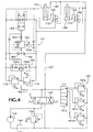
- FIG. 4 is a hydraulic circuit diagram of an alternative embodiment of the present invention.
- An exemplary paper roll clamp designated generally as 10 in FIG. 1, is mounted on a vertically-reciprocating carriage 12 carried by a lift truck mast 14.
- the load clamp comprises a frame 16 mounted on the load carriage 12 connected either fixedly thereto or, as shown in FIG. 1, by a rotator assembly 18.
- Pivotally mounted to the frame 16 at pivot points 20, 22 are a pair of opposing clamping assemblies designated generally as 24 and 26.
- the clamping assembly 24 comprises a pair of vertically-spaced clamp arms 28 and 30, having respective load-engagement pads 28a and 30a, movable separately from each other relative to the frame 16 selectively toward and away from the opposed clamping assembly 26 under the control of fluid power actuators 32 and 34 respectively, each consisting of a double-acting hydraulic cylinder connected between the frame 16 and the respective clamp arms 28 or 30.
- the opposed clamping assembly 26, on the other hand, consists of only a single clamp arm 36 having an elongated load-engagement pad 36a extending vertically so as to oppose the pads of both of the clamp arms 28 and 30.
- the clamp arm 36 pivots with respect to the frame 16 under the control of a further fluid power actuator 38. Alternatively, the arm 36 could be fixed with respect to the frame 16.
- the function of the load clamp 10 is to engage multiple stacked half-length paper rolls, such as 40 and 42, of varying different diameters simultaneously so as to transport them from one location to another. It is also necessary that the clamp be capable of engaging and carrying only a single half-length paper roll, such as roll 40. Carrying of the rolls requires that each be engaged with sufficient clamping force, by the respective pads 28a, 30a and 36a, to be able to support the weight of the loads vertically.
- the clamping force with respect to pads 28a and 30a is supplied by the pressure of hydraulic fluid tending to extend hydraulic cylinders 32 and 34, respectively.
- a hydraulic pump 44 driven by the lift truck engine, delivers fluid under pressure from a hydraulic reservoir 46 to a manually-operable clamp arm directional control valve 48 shown in its centered, or unactuated condition.
- a relief valve 50 sets an upper limit on the pressure of the fluid delivered by pump 44 by opening and bleeding fluid back to the reservoir 46 in response to excessive fluid pressure as determined by the variable setting of the relief valve 50.
- Closing the clamp arms 28 and 30 is accomplished by the lift truck operator's manipulation of valve 48 so as to move its spool to the right in FIG. 3. This delivers pressurized fluid through the input conduit 52 in parallel to lines 56 and 55 to extend hydraulic cylinders 32 and 34 respectively. Simultaneously fluid is exhausted from the opposite sides of cylinders 32 and 34 through respective exhaust lines 60 and 58.
- a selectively-variable clamping force adjuster assembly is preferably a multipressure relief valve assembly consisting of a manually-operable selector valve 61a and pressure-relief valves 61b, 61c and 61d.
- Each of the relief valves 61b, 61c and 61d is set at a different relief pressure, all lower than the relief pressure of valve 50.
- Each valve 61b, 61c and 61d thus sets a different maximum limit on the pressure of the fluid delivered through line 52 to apply clamping force through the hydraulic cylinders 32 and 34, and thereby predetermines a different maximum clamping force.
- the operator alternately selects any of the different maximum pressure limits, and thus any of the different maximum clamping forces, suitable for handling any particular load simply by adjusting the selector valve 61a to select one of the relief valves 61b, 61c or 61d.
- an easily-controllable variable pressure-relief valve or pressure-reducing valve could be associated with the conduit 52 for the same purpose.
- valve 54 combines the flows into a flow which emerges from conduit 57 and is exhausted through valve 48 to the reservoir 46.
- the valve 54 ensures that the hydraulic cylinders 32 and 34 extend simultaneously, and thus that the clamp arms 28 and 30 advance simultaneously toward the opposed clamp arm assembly 36.
- the valve 54 also causes the respective volumetric flow rates in conduits 58 and 60 to be proportional to each other and, assuming that the cylinders 32 and 34 are of the same diameter, preferably equal to each other.
- clamp arm 28 would normally be the first to encounter resistance from the larger-diameter roll 40.
- This resistance restricts the extension of cylinder 32 and reduces the flow exhausted through conduits 60 and 60a and restrictor 54a of the valve 54.
- the valve 54 begins to close restrictor 54b to accomplish a corresponding reduction in flow therethrough.
- restrictor 54a ceases due to the inability of the cylinder 32 to extend further
- restrictor 54b is substantially closed, thereby likewise preventing further extension of cylinder 34 and further closure of clamp arm 30.
- the clamp arm 30 has not yet engaged the smaller-diameter roll 42.
- the fluid pressure in conduits 52, 55 and 56 builds up to that which corresponds to the predetermined maximum clamping force adjustably set by the adjuster assembly 61. Due to the closure of restrictor 54b the pressure in conduit 58 likewise builds up to a level even somewhat higher than that in conduit 55 due to the pressure amplifying effect of the piston and rod assembly of the hydraulic cylinder 34.
- the pressure in conduit 58 is applied through a shuttle valve 66 to an override assembly indicated generally as 67 consisting of a sequence valve 62, a delay orifice 63, and an override bypass valve 64.
- valve 54 When the pressure in conduit 58 exceeds the setting of the sequence valve 62, the valve opens and, after a delay caused by the orifice 63, moves the valve 64 to its bypass condition to override the flow regulator valve 54. This enables fluid from conduit 58 to flow through valve 64 to conduit 60 and through restrictor 54a of the flow regulator valve 54. In response to such flow, regulator valve 54 opens restrictor 54b to permit an equal flow therethrough, and hydraulic cylinder 34 is therefore permitted to extend even though cylinder 32 cannot extend further due to the resistance of the larger-diameter roll 40.
- the sequence valve 62 of the override assembly 67 must be set to open and thereby override the regulator valve 54 in response to a magnitude of clamping force, represented by the clamping pressure in conduit 52, which is less than the different maximum magnitudes of clamping force predetermined by the maximum pressures selectable by the adjuster assembly 61. Otherwise, sufficient pressure will not be present in conduit 58 to open the sequence valve 62 and operate the override assembly at the lowest clamping pressure selectable by the adjuster assembly 61.
- the setting of sequence valve 62 would be such as to cause the valve 62 to open in response to a clamping pressure of approximately 48,26 bar in conduit 52.
- the delay provided by the delay orifice 63 is necessary to prevent the bypass valve 64 from opening prematurely before higher clamping pressures selected by the adjuster assembly 61 are attained. Otherwise, premature opening of the bypass valve 64 would create a low resistance to extension of the parallel cylinder 34, thus preventing the attainment of the selected maximum clamping pressure and resultant clamping force by cylinder 32.
- delay orifice 63 is a preferred structure for accomplishing the needed delay in overriding the flow regulator 54
- other delay-causing structures such as an accumulator could alternatively be employed.
- other hydraulic flow regulators such as a pair of interconnected rotary flow regulators, could be used in ensure simultaneous proportional flows through conduits 58 and 60.
- Cylinder 34 continues to extend until encountering the resistance of roll 42, at which time clamping force is applied and the pressure in conduit 55 rises to a maximum level equal to that in conduit 56, after which the directional control valve 48 may be deactivated and the rolls lifted. If only a single roll 40 were present, the load clamping operation could be halted by deactivation of control valve 48 as soon as sufficient clamping pressure had been built up in conduit 56 upon initial engagement with the roll 40, and there would be no need to further extend the cylinder 34 to further close clamp arm 30.
- the override assembly 67 has the same effect on either one of the clamp arms 28 and 30 by virtue of its ability to sense pressure in either conduit 58 or 60 through shuttle valve 66. Thus it would make no difference if the clamp 10 had been inverted by rotator 18 such that the clamp arm 30 is in the lower position for engaging roll 40. In such case, the operation of cylinder 34 and clamp arm 30 would be identical to that just described with respect to cylinder 32 and clamp arm 28, and vice versa.
- the clamp arms will open simultaneously maintaining their different positions as long as the operator actuates the control valve 48. If one clamp arm, such as 28, is used in a backhanding mode to push a load, causing substantial resistance to further opening, flow to its cylinder 32 through restrictor 54a will decrease or cease. Accordingly, the valve 54 tends to close the opposite restrictor 54b, restricting or blocking the flow to cylinder 34 because of the requirement by valve 54 for simultaneous flows to the two cylinders.
- the regulator valve 54 cannot be overridden by the operator's continued actuation of control valve 48 because opening of the sequence valve 62 is opposed, through drain line 62a, by the same pressure tending to open it. Moreover, the regulator valve 54 has no pressure limit above which the restrictors 54a and 54b can be forced to open. These factors enable a backhanding force controller consisting of variable relief valves 76 and 78 in parallel with the valve 54 to predetermine one or more maximum magnitudes of backhanding force to be imposed by fluid pressure in conduit 57 to open the clamp arms, independently of the regulator valve 54 and independently of the override assembly 67 which is temporarily disabled.
- valve 78 sets the desired maximum backhanding relief pressure for cylinder 34.
- the maximum backhanding relief pressures set by valves 76 and 78 are lower than that of relief valve 50.
- FIG. 4 shows an alternative embodiment of the invention where the fluid regulator 154 and override assembly 167 are interposed in a fluid conduit assembly through which fluid flows to the actuator cylinders 132 and 134, rather than from the cylinder as in FIG. 3, during the load clamping operation.
- those elements corresponding to the elements of FIG. 3 have the same reference numerals as in FIG. 3 increased by 100.
- the flow regulator divider/combiner valve 154 operates in a dividing mode during closure of the clamp arms, receiving pressurized fluid through conduit 152 and dividing it into simultaneous flows through restrictors 154a and 154b to ensure simultaneous extension of the cylinders 132 and 134.
- Predetermined different maximum magnitudes of clamping force are selected by means of the adjuster assembly 161.
- the override bypass valve 164 can open to permit nonsimultaneous arm closure.
- the opening of the bypass valve 164 is delayed sufficiently by the orifice 163 to permit the selected maximum clamping pressure to be achieved and trapped by a respective pilot-operated check valve such as 172 or 174.
- pressurized fluid is fed in parallel to conduits 158 and 160 from valve 148 and conduit 157 to retract cylinders 134 and 132, simultaneous retraction of the cylinders being ensured by the combining function of regulator valve 154 with respect to the fluid exhausted through conduits 156 and 155 from the cylinders 132 and 134.
- backhanding force controller relief valve 176 or 178 offers sufficient resistance to the exhaust of fluid from the second cylinder 134 or 132, respectively, that the required backhanding pressure and force can be attained in the first cylinder.
- the override bypass valve 164 is prevented from opening by opposing pressure in drain line 162a when the clamp arms are opening.
Landscapes
- Engineering & Computer Science (AREA)
- Transportation (AREA)
- Structural Engineering (AREA)
- Civil Engineering (AREA)
- Life Sciences & Earth Sciences (AREA)
- Geology (AREA)
- Mechanical Engineering (AREA)
- Chemical & Material Sciences (AREA)
- Combustion & Propulsion (AREA)
- Forklifts And Lifting Vehicles (AREA)
- Manipulator (AREA)
- Fluid-Pressure Circuits (AREA)
Claims (9)
- Pince de manipulation de charge (10) comportant un bâti (16) conçu pour être monté sur l'appareil de levage (12) d'un chariot élévateur de façon à être sélectivement mobile verticalement grâce audit appareil de levage, des premier et second ensembles de serrage (24, 26) opposés pouvant s'ouvrir et se fermer sélectivement, montés sur ledit bâti, le premier ensemble de serrage (24) comprenant au moins deux bras de pince (28, 30) mobiles séparément l'un de l'autre par rapport audit bâti, sélectivement vers et à l'écart du second ensemble de serrage (26), une paire de vérins de puissance (32, 34, 132, 134), chacun étant associé à un bras de pince respectif, destinés à déplacer lesdits bras de pince séparément l'un de l'autre sélectivement vers et à l'écart du second ensemble de serrage et à appliquer une force de serrage par l'intermédiaire desdits bras de pince dans une direction vers ledit second ensemble de serrage, un régulateur (54, 154) connecté à ladite paire de vérins pour amener les mouvements respectifs desdits deux bras de pince dans ladite direction à être simultanés l'un avec l'autre, et un ensemble de neutralisation (67, 167) capable de prendre le pas sur ledit régulateur de façon à permettre à l'un desdits bras de pince de se déplacer dans ladite direction sans mouvement simultané dans ladite direction de l'autre desdits bras de pince, caractérisée par un ensemble de dispositif de réglage de force de serrage sélectivement variable (61, 161) associé auxdits vérins et capable de prédéterminer sélectivement différentes amplitudes maximums de ladite force de serrage appliquées par lesdits bras de pince, ledit ensemble de neutralisation prenant le pas sur ledit régulateur automatiquement en réponse à une résistance au mouvement dans ladite direction dudit autre desdits deux bras de pince, indépendamment des variations sélectives dudit ensemble de dispositif de réglage de force de serrage qui prédéterminent lesdites amplitudes maximums différentes de la force de serrage.
- Dispositif selon la revendication 1, dans lequel lesdits vérins de puissance comprennent deux vérins de puissance à fluide (32, 34, 132, 134) et dans lequel ledit régulateur est un régulateur de fluide (54, 154) pouvant réguler des flux respectifs de fluide au travers desdits vérins.
- Dispositif selon la revendication 2, dans lequel ledit régulateur de fluide (54) est intercalé dans un ensemble de conduites de fluide (58, 60) au travers duquel circule un fluide depuis lesdits vérins (32, 34) durant un mouvement desdits bras de pince (28, 30) dans ladite direction allant vers ledit second ensemble de serrage (26) .
- Dispositif selon la revendication 2, dans lequel ledit régulateur de fluide (154) est intercalé dans un ensemble de conduites de fluide (152, 155, 156) au travers duquel circule un fluide vers lesdits vérins (132, 134) durant un mouvement desdits bras de pince (28, 30) dans ladite direction allant vers ledit second ensemble de serrage (26) .
- Dispositif selon la revendication 1, 2, 3 ou 4, qui comprend un contrôleur de force de retour (76, 78, 176, 178) permettant de prédéterminer une ou plusieurs amplitudes maximums de force appliquées par au moins l'un desdits bras de pince (28, 30) pendant que les deux dits bras se déplacent dans une direction s'écartant dudit second ensemble de serrage (26), indépendamment dudit régulateur (54, 154).
- Dispositif selon l'une quelconque des revendications précédentes, dans lequel ledit ensemble de neutralisation (67, 167) est conçu pour prendre le pas sur ledit régulateur (54, 154) automatiquement en réponse à une amplitude de ladite force de serrage qui est inférieure auxdites amplitudes maximums différentes de la force de serrage prédéterminées par ledit ensemble de dispositif de réglage de force de serrage (61, 161), ladite réponse étant suffisamment retardée pour permettre d'obtenir l'une quelconque desdites amplitudes maximums différentes de la force de serrage, telle qu'elle est sélectionnée par ledit ensemble de dispositif de réglage, dans l'un desdits bras de pince (28, 30) sans requérir ladite obtention dans l'autre desdits bras de pince.
- Dispositif selon la revendication 2, 3 ou 4, ou la revendication 5 lorsqu'elle dépend de la revendication 2, 3 ou 4, dans lequel ledit ensemble de dispositif de réglage de force de serrage (61, 161) est un ensemble de dispositif de réglage de pression de fluide associé auxdits vérins de puissance à fluide (32, 34, 132, 134) permettant de prédéterminer sélectivement différentes amplitudes maximums de pression de fluide amenant lesdits vérins à appliquer ladite force de serrage, ledit ensemble de neutralisation (67, 167) prenant le pas sur ledit régulateur (54, 154) automatiquement en réponse à une amplitude de ladite pression de fluide qui est inférieure auxdites amplitudes maximums différentes de pression de fluide prédéterminées par ledit ensemble de dispositif de réglage, ladite réponse étant suffisamment retardée pour permettre d'obtenir l'une quelconque desdites amplitudes maximums différentes de pression de fluide, telle qu'elle est sélectionnée par ledit ensemble de dispositif de réglage, dans l'un desdits vérins sans requérir ladite obtention dans lesdits autres vérins.
- Dispositif selon les revendications 5 et 7, dans lequel le contrôleur de pression de fluide de retour (76, 78) peut sélectivement prédéterminer une ou plusieurs amplitudes maximums de pression de fluide, en amenant lesdits vérins à écarter lesdits bras de pince dudit second ensemble de serrage, indépendamment dudit régulateur (54).
- Dispositif selon les revendications 5 et 7, dans lequel le contrôleur de pression de fluide de retour (176, 178) peut prédéterminer une ou plusieurs amplitudes maximums de pression de fluide appliquées à au moins l'un desdits vérins, pendant que les deux dits vérins écartent lesdits bras de pince dudit second ensemble de serrage, indépendamment dudit régulateur (54).
Applications Claiming Priority (2)
| Application Number | Priority Date | Filing Date | Title |
|---|---|---|---|
| US09/076,000 US5984617A (en) | 1998-05-11 | 1998-05-11 | Clamp for handling stacked loads of different sizes at different maximum clamping forces |
| US76000 | 1998-05-11 |
Publications (3)
| Publication Number | Publication Date |
|---|---|
| EP0959039A2 EP0959039A2 (fr) | 1999-11-24 |
| EP0959039A3 EP0959039A3 (fr) | 2002-09-25 |
| EP0959039B1 true EP0959039B1 (fr) | 2004-01-21 |
Family
ID=22129292
Family Applications (1)
| Application Number | Title | Priority Date | Filing Date |
|---|---|---|---|
| EP99302681A Expired - Lifetime EP0959039B1 (fr) | 1998-05-11 | 1999-04-06 | Pince pour manipuler des charges stockées de dimensions différentes avec des forces de serrage maximales différentes |
Country Status (6)
| Country | Link |
|---|---|
| US (1) | US5984617A (fr) |
| EP (1) | EP0959039B1 (fr) |
| JP (1) | JP3947630B2 (fr) |
| CA (1) | CA2261493C (fr) |
| DE (1) | DE69914252T2 (fr) |
| FI (1) | FI117134B (fr) |
Families Citing this family (23)
| Publication number | Priority date | Publication date | Assignee | Title |
|---|---|---|---|---|
| EP1268338A1 (fr) * | 2000-03-06 | 2003-01-02 | Jervis B. Webb Company | Dispositif de transport et de distribution d'articles |
| US6318949B1 (en) | 2000-07-07 | 2001-11-20 | Cascade Corporation | Clamp for handling stacked loads of different sizes |
| ITVR20020065A1 (it) * | 2002-06-12 | 2003-12-12 | Roncari S R L | Dispositivo di controllo e comando delle forze per il serraggio di carichi da trasportare mediante carrelli elevatori o simili. |
| US7056078B2 (en) * | 2003-09-24 | 2006-06-06 | Cascade Corporation | Hydraulically-synchronized clamp for handling stacked loads different sizes |
| DE102005002715A1 (de) * | 2005-01-20 | 2006-08-03 | Krones Ag | Verfahren und Vorrichtung zum Halten von Gefäßen |
| US7452176B2 (en) * | 2005-04-14 | 2008-11-18 | Cnh America Llc | Material clamping mechanism |
| ITMI20051256A1 (it) * | 2005-07-04 | 2007-01-05 | Auramo Oy | Gruppo idraulico di controllo dei bracci di una pinza e pinza comprendente tale gruppo idraulico |
| EP2036850B1 (fr) * | 2007-09-11 | 2012-05-16 | Caterpillar Work Tools B. V. | Outil de travail pour machine |
| US8091467B2 (en) * | 2008-04-30 | 2012-01-10 | Cascade Corporation | Hydraulic valve circuit with damage-control override |
| US8078315B2 (en) * | 2008-05-08 | 2011-12-13 | Cascade Corporation | Control system for a load handling clamp |
| IT1400813B1 (it) * | 2010-06-15 | 2013-07-02 | A C S S R L | Martinetto e dispositivo di movimentazione di un corpo cedevole comprendente detto martinetto |
| US9630821B2 (en) | 2011-09-06 | 2017-04-25 | Loron, Inc. | Clamping assembly for load-carrying vehicle |
| CN103511373B (zh) * | 2012-06-26 | 2016-08-03 | 安庆联动属具股份有限公司 | 同步控制液压系统 |
| US8755929B2 (en) | 2012-10-29 | 2014-06-17 | Cascade Corporation | Interactive clamp force control system for load handling clamps |
| US9114963B2 (en) * | 2013-02-26 | 2015-08-25 | Cascade Corporation | Clamping surface positioning system for mobile load-handling clamps |
| US10017366B2 (en) * | 2016-04-01 | 2018-07-10 | Cascade Corporation | Clamp having a load-clamping hydraulic cylinder with multiple telescopically extensible stages adapted to apply load clamping force alternatively responsive to load-lifting force or load size |
| US10494241B2 (en) * | 2016-09-16 | 2019-12-03 | Cascade Corporation | Hydraulic clamping systems having load side-shifting variably responsive to load weight |
| WO2020132643A1 (fr) * | 2018-12-21 | 2020-06-25 | Rightline Equipment, Inc. | Accessoire de chariot élévateur avec pince intelligente |
| US11034565B2 (en) | 2019-03-05 | 2021-06-15 | Cascade Corporation | Revolving paper roll clamp with short arm drift prevention |
| EP4118026A4 (fr) * | 2020-03-08 | 2024-04-03 | Rightline Equipment, Inc. | Pince intelligente dotée d'un clapet de blocage côté base |
| JP2022155597A (ja) * | 2021-03-31 | 2022-10-14 | 株式会社アイシン | ロボット装置 |
| US12304790B1 (en) | 2021-07-20 | 2025-05-20 | Shaw Industries Group, Inc. | Clamp adapter for lift vehicle to facilitate lifting of malleable objects |
| CN119968335A (zh) | 2022-10-04 | 2025-05-09 | 卡斯卡特公司 | 深度检测器系统 |
Family Cites Families (14)
| Publication number | Priority date | Publication date | Assignee | Title |
|---|---|---|---|---|
| US2706060A (en) * | 1952-02-23 | 1955-04-12 | John J Ferrario | Apparatus for lifting and transporting cylindrical articles |
| US3583586A (en) * | 1969-02-06 | 1971-06-08 | Jerry Fred Burton | Lift truck apparatus for manipulating storage drums |
| US3990594A (en) * | 1975-08-29 | 1976-11-09 | Cascade Corporation | Fluid-actuated clamping apparatus and circuit |
| US4127205A (en) * | 1977-09-19 | 1978-11-28 | Cascade Corporation | Lift truck load clamp for handling paper rolls |
| US4318661A (en) * | 1980-03-24 | 1982-03-09 | Dozier Equipment International Company | Drum handling device for forklift |
| US4397495A (en) * | 1981-06-29 | 1983-08-09 | Clark Equipment Company | Automatic grip control circuit for a grapple mechanism |
| FR2578824B1 (fr) * | 1985-03-15 | 1988-04-08 | Mennesson Jean Francois | Procede et dispositifs de prehension et de manutention de produits en vrac |
| JPS61241039A (ja) * | 1985-04-16 | 1986-10-27 | Nippei Toyama Corp | クランプ確認装置 |
| US4682931A (en) * | 1986-09-22 | 1987-07-28 | Cascade Corporation | Lift truck clamp for handling stacked loads of different sizes |
| FI84715C (fi) * | 1990-02-23 | 1992-01-10 | Auramo Cargo Systems Oy | Foerfarande och anordning foer behandling av last. |
| FI85260C (fi) * | 1990-07-11 | 1992-03-25 | Vesa Kaehoenen | Foerfarande och system foer att instaella hydraultrycket som verkar pao ett hydrauliskt griporgan. |
| US5308132A (en) * | 1992-10-05 | 1994-05-03 | Motorola, Inc. | Circuit assembly device for programmably controlling placement force and method thereto |
| US5417464A (en) * | 1993-12-10 | 1995-05-23 | Cascade Corporation | Slip-correcting load-clamping system |
| SE9601602L (sv) * | 1996-04-26 | 1997-07-14 | Nymek Ab | Styrning för en lasthanteringsanordning |
-
1998
- 1998-05-11 US US09/076,000 patent/US5984617A/en not_active Expired - Lifetime
-
1999
- 1999-02-12 CA CA002261493A patent/CA2261493C/fr not_active Expired - Fee Related
- 1999-03-16 JP JP07020899A patent/JP3947630B2/ja not_active Expired - Fee Related
- 1999-03-24 FI FI990656A patent/FI117134B/fi active IP Right Grant
- 1999-04-06 EP EP99302681A patent/EP0959039B1/fr not_active Expired - Lifetime
- 1999-04-06 DE DE1999614252 patent/DE69914252T2/de not_active Expired - Fee Related
Also Published As
| Publication number | Publication date |
|---|---|
| JPH11322078A (ja) | 1999-11-24 |
| FI990656A7 (fi) | 1999-11-12 |
| US5984617A (en) | 1999-11-16 |
| CA2261493C (fr) | 2002-04-16 |
| EP0959039A3 (fr) | 2002-09-25 |
| FI990656A0 (fi) | 1999-03-24 |
| JP3947630B2 (ja) | 2007-07-25 |
| DE69914252T2 (de) | 2004-11-18 |
| EP0959039A2 (fr) | 1999-11-24 |
| DE69914252D1 (de) | 2004-02-26 |
| FI117134B (fi) | 2006-06-30 |
| CA2261493A1 (fr) | 1999-11-11 |
Similar Documents
| Publication | Publication Date | Title |
|---|---|---|
| EP0959039B1 (fr) | Pince pour manipuler des charges stockées de dimensions différentes avec des forces de serrage maximales différentes | |
| US4682931A (en) | Lift truck clamp for handling stacked loads of different sizes | |
| DE69930074T2 (de) | Adaptives Lastgreifsystem | |
| US6439826B1 (en) | Adaptive load-clamping system | |
| US6843636B2 (en) | Adaptive load-clamping system | |
| AU2016423192B2 (en) | Hydraulic clamping systems having load side-shifting variably responsive to load weight | |
| JP2019509230A (ja) | 積荷リフティング力又は積荷寸法に択一的に応答して、積荷クランプ力を適用するように適応された、複数の伸張段階(ステージ)を備える伸縮自在の積荷クランピング流体圧シリンダを有するクランプ | |
| CA2155450C (fr) | Prehenseur d'exploitation forestiere | |
| US7056078B2 (en) | Hydraulically-synchronized clamp for handling stacked loads different sizes | |
| US6318949B1 (en) | Clamp for handling stacked loads of different sizes | |
| US20090050413A1 (en) | Clamp force control | |
| JPH06144795A (ja) | 流体動作積荷取扱クランプ | |
| CA2445567C (fr) | Systeme adaptable d'ancrage de charge | |
| CA2563025C (fr) | Systeme adaptable d'ancrage de charge | |
| CA2421986C (fr) | Systeme adaptable d'ancrage de charge | |
| WO1981000249A1 (fr) | Systeme d'actionnement autoreglable |
Legal Events
| Date | Code | Title | Description |
|---|---|---|---|
| PUAI | Public reference made under article 153(3) epc to a published international application that has entered the european phase |
Free format text: ORIGINAL CODE: 0009012 |
|
| AK | Designated contracting states |
Kind code of ref document: A2 Designated state(s): AT BE CH CY DE DK ES FI FR GB GR IE IT LI LU MC NL PT SE |
|
| AX | Request for extension of the european patent |
Free format text: AL;LT;LV;MK;RO;SI |
|
| PUAL | Search report despatched |
Free format text: ORIGINAL CODE: 0009013 |
|
| AK | Designated contracting states |
Kind code of ref document: A3 Designated state(s): AT BE CH CY DE DK ES FI FR GB GR IE IT LI LU MC NL PT SE |
|
| AX | Request for extension of the european patent |
Free format text: AL;LT;LV;MK;RO;SI |
|
| RIC1 | Information provided on ipc code assigned before grant |
Free format text: 7B 66F 9/18 A, 7B 66F 9/22 B |
|
| 17P | Request for examination filed |
Effective date: 20021024 |
|
| 17Q | First examination report despatched |
Effective date: 20030117 |
|
| AKX | Designation fees paid |
Designated state(s): DE GB IT |
|
| GRAP | Despatch of communication of intention to grant a patent |
Free format text: ORIGINAL CODE: EPIDOSNIGR1 |
|
| GRAS | Grant fee paid |
Free format text: ORIGINAL CODE: EPIDOSNIGR3 |
|
| GRAA | (expected) grant |
Free format text: ORIGINAL CODE: 0009210 |
|
| AK | Designated contracting states |
Kind code of ref document: B1 Designated state(s): DE GB IT |
|
| REG | Reference to a national code |
Ref country code: GB Ref legal event code: FG4D |
|
| REG | Reference to a national code |
Ref country code: IE Ref legal event code: FG4D |
|
| REF | Corresponds to: |
Ref document number: 69914252 Country of ref document: DE Date of ref document: 20040226 Kind code of ref document: P |
|
| PLBE | No opposition filed within time limit |
Free format text: ORIGINAL CODE: 0009261 |
|
| STAA | Information on the status of an ep patent application or granted ep patent |
Free format text: STATUS: NO OPPOSITION FILED WITHIN TIME LIMIT |
|
| 26N | No opposition filed |
Effective date: 20041022 |
|
| REG | Reference to a national code |
Ref country code: IE Ref legal event code: MM4A |
|
| PGFP | Annual fee paid to national office [announced via postgrant information from national office to epo] |
Ref country code: DE Payment date: 20080602 Year of fee payment: 10 |
|
| PGFP | Annual fee paid to national office [announced via postgrant information from national office to epo] |
Ref country code: IT Payment date: 20080424 Year of fee payment: 10 |
|
| PGFP | Annual fee paid to national office [announced via postgrant information from national office to epo] |
Ref country code: GB Payment date: 20080429 Year of fee payment: 10 |
|
| GBPC | Gb: european patent ceased through non-payment of renewal fee |
Effective date: 20090406 |
|
| PG25 | Lapsed in a contracting state [announced via postgrant information from national office to epo] |
Ref country code: DE Free format text: LAPSE BECAUSE OF NON-PAYMENT OF DUE FEES Effective date: 20091103 |
|
| PG25 | Lapsed in a contracting state [announced via postgrant information from national office to epo] |
Ref country code: GB Free format text: LAPSE BECAUSE OF NON-PAYMENT OF DUE FEES Effective date: 20090406 |
|
| PG25 | Lapsed in a contracting state [announced via postgrant information from national office to epo] |
Ref country code: IT Free format text: LAPSE BECAUSE OF NON-PAYMENT OF DUE FEES Effective date: 20090406 |