EP0959189B1 - Panneau d'isolation thermique - Google Patents
Panneau d'isolation thermique Download PDFInfo
- Publication number
- EP0959189B1 EP0959189B1 EP99102571A EP99102571A EP0959189B1 EP 0959189 B1 EP0959189 B1 EP 0959189B1 EP 99102571 A EP99102571 A EP 99102571A EP 99102571 A EP99102571 A EP 99102571A EP 0959189 B1 EP0959189 B1 EP 0959189B1
- Authority
- EP
- European Patent Office
- Prior art keywords
- insulation panel
- heat insulation
- figur
- thermal insulation
- panel according
- Prior art date
- Legal status (The legal status is an assumption and is not a legal conclusion. Google has not performed a legal analysis and makes no representation as to the accuracy of the status listed.)
- Expired - Lifetime
Links
Images





Classifications
-
- E—FIXED CONSTRUCTIONS
- E04—BUILDING
- E04B—GENERAL BUILDING CONSTRUCTIONS; WALLS, e.g. PARTITIONS; ROOFS; FLOORS; CEILINGS; INSULATION OR OTHER PROTECTION OF BUILDINGS
- E04B7/00—Roofs; Roof construction with regard to insulation
- E04B7/20—Roofs consisting of self-supporting slabs, e.g. able to be loaded
- E04B7/22—Roofs consisting of self-supporting slabs, e.g. able to be loaded the slabs having insulating properties, e.g. laminated with layers of insulating material
- E04B7/225—Roofs consisting of self-supporting slabs, e.g. able to be loaded the slabs having insulating properties, e.g. laminated with layers of insulating material the slabs having non-structural supports for roofing materials
-
- E—FIXED CONSTRUCTIONS
- E04—BUILDING
- E04B—GENERAL BUILDING CONSTRUCTIONS; WALLS, e.g. PARTITIONS; ROOFS; FLOORS; CEILINGS; INSULATION OR OTHER PROTECTION OF BUILDINGS
- E04B1/00—Constructions in general; Structures which are not restricted either to walls, e.g. partitions, or floors or ceilings or roofs
- E04B1/62—Insulation or other protection; Elements or use of specified material therefor
- E04B1/74—Heat, sound or noise insulation, absorption, or reflection; Other building methods affording favourable thermal or acoustical conditions, e.g. accumulating of heat within walls
- E04B1/76—Heat, sound or noise insulation, absorption, or reflection; Other building methods affording favourable thermal or acoustical conditions, e.g. accumulating of heat within walls specifically with respect to heat only
- E04B1/78—Heat insulating elements
- E04B1/80—Heat insulating elements slab-shaped
-
- Y—GENERAL TAGGING OF NEW TECHNOLOGICAL DEVELOPMENTS; GENERAL TAGGING OF CROSS-SECTIONAL TECHNOLOGIES SPANNING OVER SEVERAL SECTIONS OF THE IPC; TECHNICAL SUBJECTS COVERED BY FORMER USPC CROSS-REFERENCE ART COLLECTIONS [XRACs] AND DIGESTS
- Y02—TECHNOLOGIES OR APPLICATIONS FOR MITIGATION OR ADAPTATION AGAINST CLIMATE CHANGE
- Y02A—TECHNOLOGIES FOR ADAPTATION TO CLIMATE CHANGE
- Y02A30/00—Adapting or protecting infrastructure or their operation
- Y02A30/24—Structural elements or technologies for improving thermal insulation
- Y02A30/244—Structural elements or technologies for improving thermal insulation using natural or recycled building materials, e.g. straw, wool, clay or used tires
Definitions
- the invention relates to a rectangular thermal insulation board according to the preamble of claim 1.
- thermal insulation panels with integrated, i. DE-U-8804611
- DE-U-8804611 which are made of wood or metal and extend parallel to at least one side of the rectangle of the plate.
- the fixing strips By the arrangement of the fixing strips in each case parallel to a rectangular side, the mounting possibility of the plate is very limited, since in the attachment of slats, e.g. Roof battens, or the like. Exact distances must be maintained. As a result, the artisanal execution is difficult and it is a minimization of waste of thermal insulation panels only very limited possible.
- the aforementioned thermal insulation board by the characterizing features of claim 1 is improved so that any roof battens, strips or other supporting structures on top of the thermal insulation board can be fastened in largely arbitrary intervals. This results in easy handling of the plates, short processing times, low wastage and great variability in the practical implementation of thermally insulated entire structures including roofing.
- the thermal insulation board according to the invention can be used both in laying systems, such as pitched roofs, as well as below the rafters and in vertical structures on a wall.
- the material of the fastening strips expediently thermally insulating, which overcomes the disadvantage of the known fastening strips made of wood or metal, which have a poor thermal insulation value. Moreover, wood undergoes rotting when exposed to moisture. Integrated metal strips have the disadvantage that, as a result of the different material properties between metal and conventional thermal insulation materials, stresses arise in the board. Claims 3 and 4 are therefore directed to particularly advantageous materials for the fastening strips, which do not have the disadvantages of the known fastening strips.
- a combination of the recycled polyurethane material according to claim 3 with an embodiment of the plate itself, at least for the most part of polyurethane according to claim 5, proves to be particularly expedient.
- the thermal insulation panel according to claim 6 may be additionally provided with elastic or rigid cover layers.
- the cover layer protruding edges for covering the formed with adjacent thermal insulation panels Have butt joints.
- thermal bridge-free mounting of the thermal insulation panels they are provided according to claim 8 at two opposite end faces with stepped cutouts for hooking holders, which are attached to the substructure. This results in no thermal bridges through holders, which pass from the bottom to the top of the plates.
- the thermal insulation panels according to claim 8 may additionally contain air ducts.
- the recycled polyurethane material according to claim 3 since the fastening strips made of this material are themselves recyclable, as well as the thermal insulation panels themselves, if they consist of polyurethane according to claim 5.
- the recycled polyurethane material preferably used for the fastening strips according to claim 3 has a thermal conductivity below 0.075 W / K ⁇ m, whereby the thermal insulation of the plates is in no way impaired.
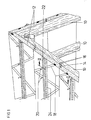
- a substructure consisting of beams 10 of a gable-shaped roof is provided, on which a thermal insulation board 12 existing insulation layer rests.
- the individual thermal insulation panels 12 are explained below angled holders 14 held, which in turn are bolted to the beams 10 of the substructure by screws 16. Flushing in the surface of each thermal insulation panel 12 are embedded in a zigzag shape at 45 ° to the sides of the plate extending, also heat-insulating and non-rotting fastening strips or mounting strips 18.
- screws or nails 20 18 supporting webs resting on the top of the thermal insulation panels 12 and 18 are fixed by metallic, approximately triangular profiled roof battens 24 to the fastening strip 18. Due to the oblique arrangement of the fastening strip 18 in the thermal insulation panels 12, the roof battens 24 in a largely arbitrary position, ie at any distance from each other safely on the mounting strip 18 and thus on the thermal insulation panels 12 are permanently attached.
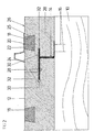
- each thermal insulation board 12 On the one hand for flush engagement of adjacent thermal insulation panels and on the other hand for hooking into the holder 14 which is parallel to the roof battens 24 extending end surface of each thermal insulation board 12 each provided with a stepped cutout 28, each emanating from each corner of the stepped cutout 28, parallel to the surface 27 extending slot 30 is extended.
- a web 32 of the holder 14 can be taken in the assembly of the thermal insulation panels 12, which results in an excellent thermal bridge-free mounting of the thermal insulation panels 12 on the substructure 10.
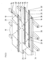
- the roof structure of Figure 3 is substantially the same structure as the roof structure of Figure 1, but in addition it is apparent from Figure 3 that the individual thermal insulation panels can be provided according to the substructure with any cutouts 34, each to an optimal adaptation to reach the substructure with minimal waste.
- the perpendicular to the roof battens 24 extending end faces of each thermal insulation panel 12 is provided on one side with a rectangular groove 36 and on the opposite side with a matching groove 36 in the rectangular groove 38.
- the attachment strips 18 are indicated in Figure 3 only by dotted lines.
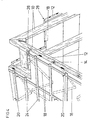
- the roof construction according to Figure 4 differs from that shown in Fig. 1 in that instead of profiled battens made of metal simple roof battens 24 are used made of wood or plastic with a rectangular cross section, which are fastened by means of screws 20 or nails to the mounting strip 18.
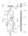
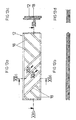
- the first embodiment according to Figures 5a-d has zigzag at about 45 ° against the sides of the rectangle sides of the thermal insulation panels 12 extending mounting strips 18 which are flush with the top 26 of the thermal insulation board 12.
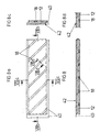
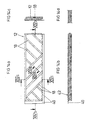
- the second embodiment illustrated in FIGS. 6a-d also has fastening strips 18 which are shaped in the same way.
- a cover layer 42 projecting on two adjoining sides beyond the outline of the thermal insulation board 12 having a protruding edge 40 is provided.
- the protruding edges 40 serve to cover the butt joints formed with adjacent thermal insulation panels 12.
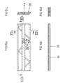
- the third embodiment according to Figures 7a-d differs from the previous two in that the fastening strips 18 are not arranged zigzag, but also parallel to each other also approximately at 45 ° against the rectangular sides of the thermal insulation board 12.
- the fourth embodiment according to FIGS. 8a-d wherein, however, in addition to the second embodiment according to FIGS. 6a-d, a cover layer 42 projecting on both sides is provided.
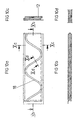
- serpentine winding fastening strips 18 are provided in the fifth embodiment according to FIGS. 9a-d and in the sixth embodiment according to FIGS. 10a-d.
- serpentine winding fastening strips 18 are provided. For the rest, these embodiments do not differ from the first or second embodiment.
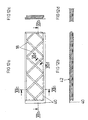
- fastening strips 18 extending over the surface of the thermal insulation panel 12 are provided, which additionally overlap one another in such a way that a karo-like pattern is formed.
- the fastening strips 18 are laid in sections parallel to each other, but the Fastening strips 18 of the longitudinal direction of the thermal insulation panel 12 successive sections are mutually perpendicular, wherein they again form an angle of 45 ° with the sides of the rectangle of the plate.
- the eleventh embodiment according to FIGS. 15a-d and the twelfth embodiment according to FIGS. 16a-d are essentially the same as the first and second embodiments according to FIGS. 5a-d or 6a-d, but additionally each contain one approximately in the longitudinal direction of the heat-insulating panel 12 in the same flush with its surface arranged air duct 44 of flachrechteckigem cross-section. They can be installed so that the air ducts merge laterally adjacent heat insulation panels 12 into each other.
Landscapes
- Engineering & Computer Science (AREA)
- Architecture (AREA)
- Physics & Mathematics (AREA)
- Electromagnetism (AREA)
- Civil Engineering (AREA)
- Structural Engineering (AREA)
- Acoustics & Sound (AREA)
- Building Environments (AREA)
- Chemical And Physical Treatments For Wood And The Like (AREA)
- Laminated Bodies (AREA)
- Secondary Cells (AREA)
- Separation, Recovery Or Treatment Of Waste Materials Containing Plastics (AREA)
- Casting Or Compression Moulding Of Plastics Or The Like (AREA)
- Thermal Insulation (AREA)
Claims (9)
- Panneau rectangulaire d'isolation thermique avec une (des) latte(s) de fixation, noyée(s) à fleur ou à proximité de la surface du panneau d'isolation thermique, parallèlement à celle-ci,
caractérisé en ce que
la (les) latte(s) de fixation (18) forme(nt) avec les côtés du rectangle du panneau d'isolation thermique (12) des angles différents de zéro. - Panneau d'isolation thermique selon la revendication 1,
caractérisé en ce que
la matière de la (des) latte(s) de fixation (18) est thermiquement isolante. - Panneau d'isolation thermique selon la revendication 2,
caractérisé en ce que
la matière est un matériau de polyuréthane recyclé, fabriqué à partir de granulés de polyuréthane en combinaison avec un liant par pressage et éventuellement traitement thermique, et qui présente une densité de 500 - 900 kg/m3 ainsi qu'une faible conductibilité thermique d'environ 0,07 W/K·m. - Panneau d'isolation thermique selon la revendication 2 ou 3,
caractérisé en ce que
la matière peut être vissée et est imputrescible. - Panneau d'isolation thermique selon l'une quelconque des revendications précédentes,
caractérisé en ce qu'
il se compose au moins pour la plus grande part de polyuréthane. - Panneau d'isolation thermique selon l'une quelconque des revendications précédentes,
caractérisé en ce qu'
il est pourvu d'une couche de recouvrement (42) sur une ou sur les deux faces. - Panneau d'isolation thermique selon la revendication 6,
caractérisé en ce que
la couche de recouvrement (42) forme un bord saillant (40) sur deux côtés adjacents du panneau d'isolation thermique (12). - Panneau d'isolation thermique selon l'une quelconque des revendications précédentes,
caractérisé en ce qu'
il présente, sur deux faces frontales opposées, des fraisages étagés (28) pour accrocher des attaches (14). - Panneau d'isolation thermique selon l'une quelconque des revendications précédentes,
caractérisé en ce qu'
il comporte, à fleur ou à proximité de sa surface (26), un puits d'aération (44) parallèle à un des côtés du rectangle.
Applications Claiming Priority (2)
| Application Number | Priority Date | Filing Date | Title |
|---|---|---|---|
| DE19822659 | 1998-05-20 | ||
| DE19822659A DE19822659A1 (de) | 1998-05-20 | 1998-05-20 | Wärmedämmplatte |
Publications (3)
| Publication Number | Publication Date |
|---|---|
| EP0959189A2 EP0959189A2 (fr) | 1999-11-24 |
| EP0959189A3 EP0959189A3 (fr) | 2001-01-17 |
| EP0959189B1 true EP0959189B1 (fr) | 2006-05-03 |
Family
ID=7868425
Family Applications (1)
| Application Number | Title | Priority Date | Filing Date |
|---|---|---|---|
| EP99102571A Expired - Lifetime EP0959189B1 (fr) | 1998-05-20 | 1999-02-11 | Panneau d'isolation thermique |
Country Status (3)
| Country | Link |
|---|---|
| EP (1) | EP0959189B1 (fr) |
| AT (1) | ATE325242T1 (fr) |
| DE (2) | DE19822659A1 (fr) |
Families Citing this family (3)
| Publication number | Priority date | Publication date | Assignee | Title |
|---|---|---|---|---|
| ITRE20110008A1 (it) * | 2011-02-14 | 2012-08-15 | Brianza Plastica Spa | Pannello componibile per la realizzazione di coperture per edifici |
| DE102012006146B4 (de) | 2012-03-28 | 2017-11-30 | STADUR-Süd-GmbH | Einrichtung zur Befestigung eines Innendämmsystems |
| EP2982809B1 (fr) | 2014-08-05 | 2017-02-01 | IWIS Insulation Waterproofing Industrial Systems S.R.L. | Système intégré d'isolation, de ventilation et de fixation pour un toit |
Family Cites Families (5)
| Publication number | Priority date | Publication date | Assignee | Title |
|---|---|---|---|---|
| DE2953539C2 (de) * | 1979-06-22 | 1983-01-13 | Fa. Manfred Helfrecht, 8598 Waldershof | Dacheindeckung |
| DE3401302A1 (de) * | 1984-01-16 | 1985-07-18 | Puren-Schaumstoff GmbH, 7770 Überlingen | Daemmplatte zur waerme- und trittschalldaemmung fuer flaechenheizanlagen |
| DE3441093A1 (de) * | 1984-11-09 | 1986-05-22 | Helfrecht, Manfred, 8598 Waldershof | Waermedaemmendes unterdach |
| DE8804611U1 (de) * | 1988-04-07 | 1988-08-11 | Fuhrmann, Reinhard, 8918 Dießen | Dämmplatte |
| DE4241053A1 (en) * | 1991-12-13 | 1993-06-17 | Thermodach Dachtechnik Gmbh | Roof heat-insulating equipment - has hooks fixed to rafters and fitting horizontally round insulating plates at side towards ridge |
-
1998
- 1998-05-20 DE DE19822659A patent/DE19822659A1/de not_active Withdrawn
-
1999
- 1999-02-11 EP EP99102571A patent/EP0959189B1/fr not_active Expired - Lifetime
- 1999-02-11 DE DE59913376T patent/DE59913376D1/de not_active Expired - Lifetime
- 1999-02-11 AT AT99102571T patent/ATE325242T1/de not_active IP Right Cessation
Also Published As
| Publication number | Publication date |
|---|---|
| DE19822659A1 (de) | 1999-11-25 |
| EP0959189A2 (fr) | 1999-11-24 |
| DE59913376D1 (de) | 2006-06-08 |
| ATE325242T1 (de) | 2006-06-15 |
| EP0959189A3 (fr) | 2001-01-17 |
Similar Documents
| Publication | Publication Date | Title |
|---|---|---|
| EP0752506A1 (fr) | Plaque de toiture pour toits inclinés | |
| DE4100623A1 (de) | Dachtafel fuer geneigte daecher | |
| DE60004462T2 (de) | Isolationselement aus mineralwolle und dachkonstruktion die dieses aufweist | |
| DE8413516U1 (de) | Elektro-flaechenheizung | |
| WO2004018798A2 (fr) | Plancher constitue d'elements individuels | |
| DE10010065C2 (de) | Abdeckanordnung für ein Gebäude, sowie Abdeckteil zur Verwendung bei einer solchen Abdeckanordnung | |
| EP0795659A1 (fr) | Construction de toit | |
| EP0959189A2 (fr) | Panneau d'isolation thermique | |
| DE3837377C2 (de) | Flachdach-Dämmkeil | |
| DE4338503A1 (de) | Unterdachkonstruktion | |
| DE3410658A1 (de) | Dachbauelement | |
| DE2708095A1 (de) | Verfahren und abstandhalter zum befestigen eines verbundelementes an einer tragkonstruktion | |
| DE2514259C2 (de) | Dachkonstruktion mit plattenförmigen Isolierstoffbauelementen sowie Abstandhalter für die Dachkonstruktion | |
| EP1052338A2 (fr) | Panneau isolant | |
| DE3600026A1 (de) | Trag- und befestigungselement | |
| DE3214502A1 (de) | Plattenfoermiges bauelement fuer die mantelbetonbauweise | |
| CH612239A5 (en) | Slab for an insulating roof substructure | |
| EP0590248A1 (fr) | Bâtiment à squelette métallique | |
| WO1999018301A1 (fr) | Toit en batiere ou en croupe | |
| AT13485U1 (de) | Isolierte Gebäudefassade | |
| EP1319770B1 (fr) | Panneau isolant pour toiture | |
| EP0008671A1 (fr) | Panneau isolant pour toits aérés à chevrons | |
| DE29604846U1 (de) | Dachkonstruktion | |
| DE1925494A1 (de) | Plattenfoermiges Bauelement | |
| DE102005029361B3 (de) | First- oder Gratabdeckung |
Legal Events
| Date | Code | Title | Description |
|---|---|---|---|
| PUAI | Public reference made under article 153(3) epc to a published international application that has entered the european phase |
Free format text: ORIGINAL CODE: 0009012 |
|
| AK | Designated contracting states |
Kind code of ref document: A2 Designated state(s): AT CH DE LI |
|
| AX | Request for extension of the european patent |
Free format text: AL;LT;LV;MK;RO;SI |
|
| PUAL | Search report despatched |
Free format text: ORIGINAL CODE: 0009013 |
|
| AK | Designated contracting states |
Kind code of ref document: A3 Designated state(s): AT BE CH CY DE DK ES FI FR GB GR IE IT LI LU MC NL PT SE |
|
| AX | Request for extension of the european patent |
Free format text: AL;LT;LV;MK;RO;SI |
|
| 17P | Request for examination filed |
Effective date: 20010221 |
|
| AKX | Designation fees paid |
Free format text: AT CH DE LI |
|
| GRAP | Despatch of communication of intention to grant a patent |
Free format text: ORIGINAL CODE: EPIDOSNIGR1 |
|
| GRAS | Grant fee paid |
Free format text: ORIGINAL CODE: EPIDOSNIGR3 |
|
| GRAA | (expected) grant |
Free format text: ORIGINAL CODE: 0009210 |
|
| RAP1 | Party data changed (applicant data changed or rights of an application transferred) |
Owner name: PUREN GMBH |
|
| AK | Designated contracting states |
Kind code of ref document: B1 Designated state(s): AT CH DE LI |
|
| REG | Reference to a national code |
Ref country code: CH Ref legal event code: EP |
|
| REF | Corresponds to: |
Ref document number: 59913376 Country of ref document: DE Date of ref document: 20060608 Kind code of ref document: P |
|
| REG | Reference to a national code |
Ref country code: CH Ref legal event code: NV Representative=s name: R. A. EGLI & CO. PATENTANWAELTE |
|
| PLBE | No opposition filed within time limit |
Free format text: ORIGINAL CODE: 0009261 |
|
| STAA | Information on the status of an ep patent application or granted ep patent |
Free format text: STATUS: NO OPPOSITION FILED WITHIN TIME LIMIT |
|
| 26N | No opposition filed |
Effective date: 20070206 |
|
| PGFP | Annual fee paid to national office [announced via postgrant information from national office to epo] |
Ref country code: CH Payment date: 20080225 Year of fee payment: 10 |
|
| PGFP | Annual fee paid to national office [announced via postgrant information from national office to epo] |
Ref country code: AT Payment date: 20080222 Year of fee payment: 10 |
|
| REG | Reference to a national code |
Ref country code: CH Ref legal event code: PL |
|
| PG25 | Lapsed in a contracting state [announced via postgrant information from national office to epo] |
Ref country code: LI Free format text: LAPSE BECAUSE OF NON-PAYMENT OF DUE FEES Effective date: 20090228 Ref country code: CH Free format text: LAPSE BECAUSE OF NON-PAYMENT OF DUE FEES Effective date: 20090228 Ref country code: AT Free format text: LAPSE BECAUSE OF NON-PAYMENT OF DUE FEES Effective date: 20090211 |
|
| REG | Reference to a national code |
Ref country code: DE Ref legal event code: R082 Ref document number: 59913376 Country of ref document: DE Representative=s name: DAUB UND KOLLEGEN, DE |
|
| PGFP | Annual fee paid to national office [announced via postgrant information from national office to epo] |
Ref country code: DE Payment date: 20130228 Year of fee payment: 15 |
|
| REG | Reference to a national code |
Ref country code: DE Ref legal event code: R119 Ref document number: 59913376 Country of ref document: DE |
|
| REG | Reference to a national code |
Ref country code: DE Ref legal event code: R119 Ref document number: 59913376 Country of ref document: DE Effective date: 20140902 |
|
| PG25 | Lapsed in a contracting state [announced via postgrant information from national office to epo] |
Ref country code: DE Free format text: LAPSE BECAUSE OF NON-PAYMENT OF DUE FEES Effective date: 20140902 |