EP0959214A2 - Möbelscharnier mit Einschnappaktion parallel zur Montagefläche der Basisplatte - Google Patents
Möbelscharnier mit Einschnappaktion parallel zur Montagefläche der Basisplatte Download PDFInfo
- Publication number
- EP0959214A2 EP0959214A2 EP99201105A EP99201105A EP0959214A2 EP 0959214 A2 EP0959214 A2 EP 0959214A2 EP 99201105 A EP99201105 A EP 99201105A EP 99201105 A EP99201105 A EP 99201105A EP 0959214 A2 EP0959214 A2 EP 0959214A2
- Authority
- EP
- European Patent Office
- Prior art keywords
- base plate
- intermediate body
- hinge
- central core
- hinge according
- Prior art date
- Legal status (The legal status is an assumption and is not a legal conclusion. Google has not performed a legal analysis and makes no representation as to the accuracy of the status listed.)
- Withdrawn
Links
Images


Classifications
-
- E—FIXED CONSTRUCTIONS
- E05—LOCKS; KEYS; WINDOW OR DOOR FITTINGS; SAFES
- E05D—HINGES OR SUSPENSION DEVICES FOR DOORS, WINDOWS OR WINGS
- E05D7/00—Hinges or pivots of special construction
- E05D7/12—Hinges or pivots of special construction to allow easy detachment of the hinge from the wing or the frame
- E05D7/123—Hinges or pivots of special construction to allow easy detachment of the hinge from the wing or the frame specially adapted for cabinets or furniture
- E05D7/125—Hinges or pivots of special construction to allow easy detachment of the hinge from the wing or the frame specially adapted for cabinets or furniture the hinge having two or more pins
-
- E—FIXED CONSTRUCTIONS
- E05—LOCKS; KEYS; WINDOW OR DOOR FITTINGS; SAFES
- E05Y—INDEXING SCHEME ASSOCIATED WITH SUBCLASSES E05D AND E05F, RELATING TO CONSTRUCTION ELEMENTS, ELECTRIC CONTROL, POWER SUPPLY, POWER SIGNAL OR TRANSMISSION, USER INTERFACES, MOUNTING OR COUPLING, DETAILS, ACCESSORIES, AUXILIARY OPERATIONS NOT OTHERWISE PROVIDED FOR, APPLICATION THEREOF
- E05Y2600/00—Mounting or coupling arrangements for elements provided for in this subclass
- E05Y2600/50—Mounting methods; Positioning
- E05Y2600/52—Toolless
- E05Y2600/53—Snapping
-
- E—FIXED CONSTRUCTIONS
- E05—LOCKS; KEYS; WINDOW OR DOOR FITTINGS; SAFES
- E05Y—INDEXING SCHEME ASSOCIATED WITH SUBCLASSES E05D AND E05F, RELATING TO CONSTRUCTION ELEMENTS, ELECTRIC CONTROL, POWER SUPPLY, POWER SIGNAL OR TRANSMISSION, USER INTERFACES, MOUNTING OR COUPLING, DETAILS, ACCESSORIES, AUXILIARY OPERATIONS NOT OTHERWISE PROVIDED FOR, APPLICATION THEREOF
- E05Y2900/00—Application of doors, windows, wings or fittings thereof
- E05Y2900/20—Application of doors, windows, wings or fittings thereof for furniture, e.g. cabinets
Definitions
- the invention relates to snap engagement hinges, that is to say the hinges nowadays widely used, wherein a hinge arm is secured to a base plate in a rapid manner by means of a snap-type engagement system, which is also known in the field as "clip".
- the arm of those hinges is secured to the base plate in at least two points, one at the front and the other at the rear with respect to its longitudinal extension, by causing the arm to rotate about the first point and locking it by snap engagement in the second point for preventing any separation of the coupled parts.
- the arm of these hinges has at the end opposite that where it is engaged on the base plate, articulated levers which engage on a cup-like support: such levers provide the hinge with the well-known characteristic rotational and translational opening and closing movement of doors.
- the hinges under consideration herein also comprise an intermediate body arranged between the base plate and the arm mounted thereon; the body is fixed to the arm in an adjustable manner by means of suitable screws, and a pin or projections are usually provided transversely to it for engaging with the base plate, in order to enable the arm to rotate with respect thereto during the mounting of the hinge.
- the hinges fulfill strict requirements; the latter relate both to aspects of the dimensional type, for example the distance between predetermined points of the hinges, and to functional aspects such as the resistance to predetermined tests.
- hinges having an intermediate body can be used to lock the hinge arm to which it is fixed: this fact does not change the situation because once the intermediate body is secured to the hinge arm, it forms together with it a single element which is then applied on the base plate as already explained above.
- a rocker arm resiliently urged by a spring; such a rocker arm is basically a small lever mounted on the base plate or on the intermediate body, which is provided with a part shaped as a hook that engages with a projection of the intermediate body or the base plate, depending on where the rocker arm is applied.
- the rocker arm also oscillates in a plane perpendicular to the mounting plane of the base plate, that is to say the plane of the wall of the item of furniture to which the base plate is secured: this means that the oscillating movement of the rocker arm takes place in a plane which in most cases, coincides with the plane of rotation for mounting the hinge arm on the base plate.
- the object of the invention is to provide a hinge which satisfies these requirements; such an object is achieved by a hinge the features thereof are stated in the claims appended to this description.
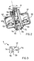
- the hinge comprises an arm 2 which is connected to a cup-like support 3 by means of articulated levers 4 in the manner known in the art and referred to above; both the cup-like support 3 and the arm 2 of the hinge are customarily shaped and, as regards the arm 2, it has a "U" type cross-section.
- an intermediate body 5 forming part of the hinge 1 there are an intermediate body 5, a base plate 6 and resilient engagement means, in this case formed by a linear flexure spring 7 obtained using steel music wire having a square cross-section.
- hinge arm 2 there are a threaded hole 21 and a notch 23 open towards one end of the arm, of the type generally present in many commercially available hinges and which are used for the adjustment of the latter by means of screws and the like not shown in the drawings.
- the intermediate body 5 is provided with a notch 51 and a threaded hole 53 that, when the hinge arm 2 is mounted on the intermediate body 5, are aligned with those already mentioned.
- the intermediate body 5 also has a U-shaped cross-section and its dimensions are such as to enable it to be accommodated inside the hinge arm 2; in addition, the intermediate body 5 has on its lateral sides 54 two projections 55 extending transversely inwards and foreseen to engage with cavities 65 in the base plate 6: the intermediate body can rotate about said projections 55 and cavities 65, in order to be secured to the plate as will be explained more clearly hereinafter.
- the projections might however be replaced by a pin extending between the sides of the intermediate body and transversely thereto, or their arrangement could be exchanged with that of the cavities, placing the latter on the intermediate body and the projections on the base plate; such solutions already exist in many hinges available in commerce.
- the intermediate body 5 has a tail appendage 56; the tail appendage 56 is advantageously produced in one piece with the intermediate body by bending an extension of a central portion 57 thereof, i.e. the portion between its lateral sides 54.
- the tail appendage 56 of the intermediate body also has a profile (see Figure 3) which defines a seat 58 mainly extending in a direction parallel to the central portion 57, and an inclined surface 59 which will be considered in greater detail hereinafter.
- the base plate 6 has instead the typical cross-shape formed by a central core 60 with two wings 61, 62 extending laterally therefrom; the wings 61, 62 also have the usual slot-shaped holes 63 for the screws for securing the plate 6 to the portion of the item of furniture to which it is associated.
- the central core 60 of the base plate also has a U-shaped cross-section and terminates in a tail appendage 64 formed in one piece therewith by bending a tip extension of it; the tail appendage 64 is provided with an opening 66 through which the linear spring 7 extends (see Figure 2).
- the linear spring 7 is secured to the core 60 of the plate in the area of a hole 67 in the latter; more specifically, according to a preferred embodiment of the invention the hole 67 has an edge 67a which projects downwards from the central core 60 and is clinched in such a manner as to support the linear spring 7, which is for that purpose suitably shaped with an end in the form of an eyelet 70, juxtaposed with the central core.
- the linear spring 7 is provided with a grip 71, in order to facilitate the manipulation thereof, which however is not indispensable and could therefore not be present.
- the hinge 1 is assembled in the manner that will now be explained.
- the hinge arm 2 and the intermediate body 5 are fixed to one another by means of two screws, not shown in the drawings, one of which engages in the hole 21 and in the notch 51, while the other engages in the notch 23 and in the hole 53.
- the hinge arm and the intermediate body so assembled are subsequently applied on the base plate 6, by causing them to rotate about an axis which is defined by the cavities 65 and the projections 55 coupled to one another.
- the tail appendage 56 of the intermediate body is introduced into the slit 68 in the base plate, and its inclined surface 59 thus comes into contact with the linear spring 7; at that point, by slightly pressing the hinge arm 2 together with the intermediate body 5 against the base plate 6, the inclined surface 59 cause the buckling of the linear spring 7 by bending it resiliently in a plane parallel to that of the central core 60 of the base plate 6.
- the inclined surface 59 passes over the linear spring 7 which, as a result of its resilient reaction, snaps into the seat 58, thus ensuring the locking of the intermediate body 5 and of the hinge arm solid therewith.
- the snap engagement means i.e. the linear spring 7 and the tail appendage 56 of the intermediate body, are prevented form working because they operate in a plane perpendicular to that of the rotation of the hinge arm.
- the engagement system according to the invention is a non-reversible mechanism.
- hinges of the type concerned herein are produced by forming their individual parts (base plate, intermediate body, hinge arm) from a flat metal sheet, following to successive stages of blanking and drawing carried out using dies mounted on presses.
- the snap engagement system comprises the mounting only of the linear spring 7.
- This operation is carried out after having inserted the linear spring 7 into the opening 66 in the tail appendage 64 and by securing it to the base plate in the region of the hole 67 with clinched edge: this last stage can be carried out by means of a simple stamping operation which does not require special manual intervention on the part of the operators, as might be the case if welding, rivets or other equivalent techniques were used for securing the linear spring 7.
- both appendages can be obtained by stamping at the same time with the intermediate body and the base plate, given that they are only a bent extension thereof; this means that it is not necessary to carry out additional operations in order to form the tail pieces, compared with those normally required for the production per se of the intermediate body and of the base plate, it being sufficient to provide the appropriate modifications to the dies for the latter.
- the snap engagement prevents the arm from being detached from the base plate as a result of its rotation in the direction opposite to the mounting one; in practice, it may be said that the snap engagement restrains the hinge arm against forces which may cause it to be lifted from the base plate.
- the engagement system does not help to withstand the forces acting in the axial direction relative to the arm; that is to say, the engagement system does not restrain the arm relative to the base plate, preventing their mutual detachment along their longitudinal axis.
- Known hinges are generally provided with other means for that purpose, such as abutments on the arm and on the base plate, in order to ensure their stable axial coupling.
- the tail appendage 56 which, in addition to forming part of the snap engagement means thereby serving to prevent the lifting of the hinge arm 2 from the base plate 6, is also aimed at preventing axial movements of the intermediate body 5 (and of the hinge arm 2 secured thereon) relative to the base plate 6.
- the intermediate body is applied on the base plate, it is restrained thereon in the longitudinal direction by the tail appendage 56 which is inserted in the slit 68, and by the coupling between the projections 55 and the cavities 65.
- the hinge of the invention can be further simplified with respect to the known hinges, thus making it even more advantageous than them.
- the snap engagement rocker arms generally oscillate in the plane where the rotation of the hinge arm (and of the intermediate body, where appropriate) takes place, or in a plane perpendicular to the mounting plane of the base plate.
- the rocker arm is mounted on the base plate, it has to rotate towards the plane where the plate is secured, in order to be able to release the hinge arm from the snap engagement: consequently, the rotation of the rocker arm is necessarily limited by the mounting plane of the base plate and therefore it can sometimes become rather problematic.
- the wideness of the buckling of the spring can be sufficiently large to not interfere with the side walls of the central core.
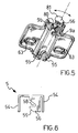
- the second embodiment of the invention differs from the hinge of Figures 1 to 3 by the fact that the snap engagement means in this case comprise a rocker arm 8 resiliently urged by a helicoidal spring 9.
- the rocker arm 8 has a flattened portion which is mounted under the central core 60 of the base plate 6 by means of a pin 10 and on which the helicoidal spring 9 acts; the helicoidal spring 9 is one which also works by flexure and is applied to the pin 10 in such a manner that (see Figure 5) one of its legs 9a acts on the side of the central core 60, while the other, 9b, is in contact with a protrusion 80 projecting from the rocker arm 8.
- the rocker arm 8 has a shaped grip 81 which can be pushed by a user for causing it to oscillate while being opposed by the helicoidal spring 9.
- the intermediate body 5 is provided with a tail appendage 56 which is produced in one piece with the central portion 57 of the intermediate body 5 by bending an end extension thereof; the shape of the tail appendage 56 having the seat 58 and the inclined surface 59 is also similar to the shape already seen: the fact that it is arranged differently (see especially Figures 3 and 6) or has different proportions, clearly has no effect on its functions and the mode of operation.
- the base plate 6 does not have a slit while its rear end 69, that is to say the end remote from the cavities 65, has a stepped profile for coupling with the tail appendage 56 of the intermediate body.
- rocker arm can snap into the seat 58, locking the intermediate body and the hinge arm onto the base plate.
- the pin 10 is advantageously mounted in a position displaced with respect to the longitudinal axis of symmetry of the central core 60.
- the intermediate body (and the hinge arm) is anchored to the base plate in the longitudinal direction, by means of the cavities 65/projections 55 coupling at the front and by means of the tail appendage 56 accommodated in the end 69, at the rear.
- the tail appendage 56 in addition to forming part of the snap engagement means, operates as a stop element for the intermediate body 5 against the forces acting axially relative thereto which could detach it from the base plate.
- a first possible change which could be envisaged is to produce the tail appendage 56 of the intermediate body by bending an extension of its sides 54, instead of an extension of its central portion; in such a situation it might perhaps be necessary to modify slightly the profile of the tail appendage 56 for allowing it to be engaged by the linear spring 7 or the rocker arm 8 as explained above, but from the functional point of view the tail appendage 56 would not change its role.
- tail appendage 56 to provide undercuts or openings in the sides 54 of the intermediate body 5 suitable for cooperating with the linear spring or the rocker arm: such solutions, however, appear to be of lesser value than those considered in the previous examples, also because their carrying out would involve specific operations for manufacturing the hinge.
Landscapes
- Engineering & Computer Science (AREA)
- Mechanical Engineering (AREA)
- Hinges (AREA)
- Supports Or Holders For Household Use (AREA)
Applications Claiming Priority (2)
| Application Number | Priority Date | Filing Date | Title |
|---|---|---|---|
| IT98MI000794 IT1299087B1 (it) | 1998-04-16 | 1998-04-16 | Cerniera per mobili con movimento di aggancio a scatto, parallelo al piano di applicazione della piastra di base. |
| ITMI980794 | 1998-04-16 |
Publications (2)
| Publication Number | Publication Date |
|---|---|
| EP0959214A2 true EP0959214A2 (de) | 1999-11-24 |
| EP0959214A3 EP0959214A3 (de) | 2000-09-06 |
Family
ID=11379776
Family Applications (1)
| Application Number | Title | Priority Date | Filing Date |
|---|---|---|---|
| EP99201105A Withdrawn EP0959214A3 (de) | 1998-04-16 | 1999-04-08 | Möbelscharnier mit Einschnappaktion parallel zur Montagefläche der Basisplatte |
Country Status (2)
| Country | Link |
|---|---|
| EP (1) | EP0959214A3 (de) |
| IT (1) | IT1299087B1 (de) |
Cited By (2)
| Publication number | Priority date | Publication date | Assignee | Title |
|---|---|---|---|---|
| CN105909098A (zh) * | 2016-06-08 | 2016-08-31 | 黑学智 | 一种家具铰链的底座拆装结构 |
| CN111350429A (zh) * | 2019-05-25 | 2020-06-30 | 广东联迅精密制造有限公司 | 一种缓冲铰链快速拆装结构 |
Family Cites Families (4)
| Publication number | Priority date | Publication date | Assignee | Title |
|---|---|---|---|---|
| DE3161939D1 (en) * | 1980-07-15 | 1984-02-23 | Salice Arturo Spa | Hinge arm with mounting plate |
| DE3532650A1 (de) * | 1985-09-13 | 1987-03-26 | Lautenschlaeger Kg Karl | Moebelscharnier |
| DE3775652D1 (de) * | 1986-08-08 | 1992-02-13 | Salice Arturo Spa | Scharnierarm fuer ein moebelscharnier o.dgl. |
| DE9212492U1 (de) * | 1992-09-17 | 1994-01-27 | Prämeta Gesellschaft für Präzisionsmetall- und Kunststofferzeugnisse mbH & Co KG, 51107 Köln | Scharnier |
-
1998
- 1998-04-16 IT IT98MI000794 patent/IT1299087B1/it active IP Right Grant
-
1999
- 1999-04-08 EP EP99201105A patent/EP0959214A3/de not_active Withdrawn
Cited By (2)
| Publication number | Priority date | Publication date | Assignee | Title |
|---|---|---|---|---|
| CN105909098A (zh) * | 2016-06-08 | 2016-08-31 | 黑学智 | 一种家具铰链的底座拆装结构 |
| CN111350429A (zh) * | 2019-05-25 | 2020-06-30 | 广东联迅精密制造有限公司 | 一种缓冲铰链快速拆装结构 |
Also Published As
| Publication number | Publication date |
|---|---|
| EP0959214A3 (de) | 2000-09-06 |
| ITMI980794A1 (it) | 1999-10-16 |
| IT1299087B1 (it) | 2000-02-07 |
Similar Documents
| Publication | Publication Date | Title |
|---|---|---|
| US6318769B1 (en) | Backset adjustment structure of dead bolt assembly for door lock | |
| JP4164329B2 (ja) | ラッチ装置 | |
| KR100253616B1 (ko) | 시계 밴드용 버클 | |
| CN111769406A (zh) | 拉带解锁结构及连接器 | |
| US5655799A (en) | Latch assembly | |
| JP4040355B2 (ja) | ヒンジ | |
| JPS643370Y2 (de) | ||
| EP1306027B1 (de) | Zuglasche für Reissverschluss | |
| US5667258A (en) | Latch assembly | |
| EP0959214A2 (de) | Möbelscharnier mit Einschnappaktion parallel zur Montagefläche der Basisplatte | |
| JP2882778B2 (ja) | オーバセンタトグル式ラッチ | |
| US3998077A (en) | Draw bolt | |
| CA2555927A1 (en) | Miniture circuit breaker | |
| JPH08175272A (ja) | 収納ボックスにおける蓋体のロック装置 | |
| CN216476805U (zh) | 一种汽车背门锁紧急开启机构 | |
| JP2009247680A (ja) | 耳飾りと耳飾りの交換方法 | |
| JP4036316B2 (ja) | 自動車ドアのアウタハンドルとラッチオープンレバーとの結合構造 | |
| CN212614243U (zh) | 一种铰链底座的快拆装结构 | |
| US5048879A (en) | Door lock for an automobile | |
| TWI870218B (zh) | 鎖扣裝置之改良結構 | |
| JP3397990B2 (ja) | 自動車用アウトサイドハンドル装置用ハンドルの製造方法 | |
| WO2025026105A1 (zh) | 一种隐形拉链的有锁拉头 | |
| JP2508242B2 (ja) | ワゴンの引出し施錠装置 | |
| JP2560966Y2 (ja) | 押釦スイッチ | |
| JP4235367B2 (ja) | 錠前のストッパー係合解除機構 |
Legal Events
| Date | Code | Title | Description |
|---|---|---|---|
| PUAI | Public reference made under article 153(3) epc to a published international application that has entered the european phase |
Free format text: ORIGINAL CODE: 0009012 |
|
| AK | Designated contracting states |
Kind code of ref document: A2 Designated state(s): AT BE CH DE DK ES FI FR GB GR IE IT LI LU NL PT SE |
|
| AX | Request for extension of the european patent |
Free format text: AL;LT;LV;MK;RO;SI |
|
| RIN1 | Information on inventor provided before grant (corrected) |
Inventor name: BRIOSCHI, EDOARDO |
|
| PUAL | Search report despatched |
Free format text: ORIGINAL CODE: 0009013 |
|
| AK | Designated contracting states |
Kind code of ref document: A3 Designated state(s): AT BE CH CY DE DK ES FI FR GB GR IE IT LI LU MC NL PT SE |
|
| AX | Request for extension of the european patent |
Free format text: AL;LT;LV;MK;RO;SI |
|
| 17P | Request for examination filed |
Effective date: 20010226 |
|
| AKX | Designation fees paid |
Free format text: AT BE CH DE DK ES FI FR GB GR IE IT LI LU NL PT SE |
|
| AXX | Extension fees paid |
Free format text: SI PAYMENT 20010226 |
|
| STAA | Information on the status of an ep patent application or granted ep patent |
Free format text: STATUS: THE APPLICATION IS DEEMED TO BE WITHDRAWN |
|
| 18D | Application deemed to be withdrawn |
Effective date: 20021102 |