EP0959228A1 - Gestaffelte Anordnung von Filmkühlungsbohrungen - Google Patents
Gestaffelte Anordnung von Filmkühlungsbohrungen Download PDFInfo
- Publication number
- EP0959228A1 EP0959228A1 EP98810475A EP98810475A EP0959228A1 EP 0959228 A1 EP0959228 A1 EP 0959228A1 EP 98810475 A EP98810475 A EP 98810475A EP 98810475 A EP98810475 A EP 98810475A EP 0959228 A1 EP0959228 A1 EP 0959228A1
- Authority
- EP
- European Patent Office
- Prior art keywords
- row
- bores
- outlet openings
- holes
- arrangement according
- Prior art date
- Legal status (The legal status is an assumption and is not a legal conclusion. Google has not performed a legal analysis and makes no representation as to the accuracy of the status listed.)
- Granted
Links
Images




Classifications
-
- F—MECHANICAL ENGINEERING; LIGHTING; HEATING; WEAPONS; BLASTING
- F01—MACHINES OR ENGINES IN GENERAL; ENGINE PLANTS IN GENERAL; STEAM ENGINES
- F01D—NON-POSITIVE DISPLACEMENT MACHINES OR ENGINES, e.g. STEAM TURBINES
- F01D5/00—Blades; Blade-carrying members; Heating, heat-insulating, cooling or antivibration means on the blades or the members
- F01D5/12—Blades
- F01D5/14—Form or construction
- F01D5/18—Hollow blades, i.e. blades with cooling or heating channels or cavities; Heating, heat-insulating or cooling means on blades
- F01D5/186—Film cooling
-
- F—MECHANICAL ENGINEERING; LIGHTING; HEATING; WEAPONS; BLASTING
- F05—INDEXING SCHEMES RELATING TO ENGINES OR PUMPS IN VARIOUS SUBCLASSES OF CLASSES F01-F04
- F05D—INDEXING SCHEME FOR ASPECTS RELATING TO NON-POSITIVE-DISPLACEMENT MACHINES OR ENGINES, GAS-TURBINES OR JET-PROPULSION PLANTS
- F05D2260/00—Function
- F05D2260/20—Heat transfer, e.g. cooling
- F05D2260/202—Heat transfer, e.g. cooling by film cooling
Definitions
- the invention relates to a bore arrangement for forming a cooling film a wall of a component acted upon by a hot gas stream, in particular a turbine blade or combustion chamber of a gas turbine, according to the Preamble of claim 1.
- a test vehicle for simulating a cooling film is known at which is provided with a flat plate with holes which the blow-out openings of tubes positioned at an angle of 35 ° to the plane of the plate represent.
- the holes are arranged in two in relation to the Main flow direction of staggered, laterally offset rows.
- the test series described in this article show a significant increase of the cooling effect over a single row of holes.
- This Effect is attributed to the fact that the cooling air jets emerging from the first row the cooling air jets emerging from the second row onto the surface deflect the wall to be cooled and thus improve its cooling effect.
- the cooling film of the first row of holes over the cooling line of the row of second holes and additionally protects it against the penetration of hot gas.
- the turbine blade known from EP 0 501 813 B1 points in a similar direction, in the case of different variants of hole arrangements for forming a cooling film be proposed in a double row.
- One of the variants suggests two small diameter holes in the first row assign a larger diameter hole to the second row.
- the assignments of the holes in the first row to the respective holes in the second Row is given by the fact that these are flow branches of a common one Entry opening are executed.
- the disadvantage of this solution is the high cooling air consumption caused by the high number of outlet openings of the first row is due.
- the disadvantage is the low flexibility in the choice of the direction of the individual holes to be seen, since these start from a single, common entry bore.
- those that emerge from the holes in the first row Cooling air jets a lateral, ie. H. Directional component perpendicular to the main flow, which in many Cases is undesirable.
- the invention tries to avoid the disadvantages described. You are the The task of specifying a drilling arrangement of the type mentioned at the outset, which allows a cooling film of high efficiency with reduced cooling air requirement to train.
- the number of holes in the first Row is substantially equal to or less than the number of holes in the second row.
- a particularly effective overlay of the holes in the first row trained partial film with that of the second row arises if according to a preferred variant, the holes in the first row essentially is aligned axially parallel to the bores of the second row.
- a further improvement in the cooling effectiveness can be achieved if at least the holes in the second row in the area of the outlet openings Have axial section with a funnel-shaped cross-sectional profile.
- the hereby achieved cross-sectional enlargement in the exit plane leads to a reduction the exit velocity of the partial cooling flows. It can be an advantage be when the axis of rotation of the funnel-shaped axial section is not coaxial to the axis of rotation of the rest of the hole, but somewhat in the direction of Main flow is inclined. As a result, the emerging cooling air jet becomes essential brought closer to the surface to be cooled.
- a further increase in cooling capacity can be achieved if in a special one preferred variant also the bores of the first row in the area of the outlet openings have an axial section with a funnel-shaped cross-sectional profile.
- the condition must also be met that the The area of each of the outlet openings of the first row is smaller than the area of each the outlet openings of the second row.
- exemplary embodiments of the invention are based on a component section shown, which in particular is part of a turbine blade or combustion chamber of a gas turbine.
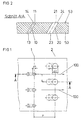
- the bore arrangement shown in FIGS. 1 and 2 has a first row 1 from bores 10 to The bores 10 are arranged equidistant from one another. In the case of a turbine blade, the bores 10 can extend over the extend the entire height of the bucket.
- Adjacent and downstream of row 1 is a second row 2 of holes 20 provided.
- the bores 10, 20 are rotationally symmetrical executed with respect to axes of rotation 11, 21 and thus have a cylindrical Basic form.
- the bores 10, 20 penetrate completely in the axial direction a wall 50 with the formation of inlet openings 13, 23 and outlet openings 14, 24.
- the number of bores 10 of the first row 1 is essentially the same Number of holes 20 in the second row 2.
- the expression “essentially equal "in this context means that due to the staggered shown here Arrangement of the holes 10 in relation to the holes 20 one of the two rows 1, 2 have an additional hole for reasons of symmetry can, but otherwise an assignment between the holes 10 of the first Row 1 and the holes 20 of the second row 2 is predetermined. In the embodiment 1, the assignment is such that the outlet openings 24 of the holes 20 with respect to the direction of the hot gas flow 100 in the The middle between the outlet openings 14 of the bores 10 is arranged. This Type of staggering has proven to be particularly beneficial in terms of effectiveness of the cooling film developing.
- the diameter d1 of the bores 10 is smaller than the diameter d2 of the Bores 20.
- the diameter is d1 in each case half the diameter d2. This relation ensures that the through the holes 10 emerging cooling film completely over the through the Bores 20 emerging further partial cooling film and the latter against the Wall 50 presses in the area of surface 53.
- the comparative small diameter d1 the air consumption in relation to the achieved Extremely low cooling effect.
- the choice of the distance is of particular importance p between the two rows 1, 2. It is correlated with the diameters d1, d2 of holes 10, 20 and should be five times the arithmetic value Do not exceed by means of the diameters d1, d2. Otherwise there is the danger of an insufficient interaction between the partial cooling films emerging from holes 10 and 20.
- the axes of rotation 11, 21 are axially parallel aligned and slightly inclined towards the hot gas flow 100.
- the emerging partial cooling air flows are somewhat in the direction blown onto the surface 53 to be cooled and as a result of the additional Effect of the hot gas flow 100 completely redirected.
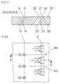
- both have the bores 10 'and the bores 20' axial sections 16 ', 26', the expand in a funnel shape towards outlet openings 14 ', 24'.
- the area of the exit opening 14 ' is smaller than the area of the outlet openings 24'.
- the funnel-shaped axial sections 16 ', 26' are not an exemplary embodiment rotationally symmetrical to the axes of rotation 11 ', 21' of the bores 10 ', 20', but run more inclined towards the surface 53 '.
- FIGS. 4 to 7 are identical cylindrical bores 10 of the first row 1 as related are described with Figures 1 and 2.
- the peculiarity lies in the Design of the bores 20 'of the second row 2', which is funnel-shaped are.
- the embodiment shown in Figures 4 and 5 has bores 20 ' are funnel-shaped in their entire axial extent.
- the entry openings 23 ' correspond to the variants described above circular or in the case of those shown, pointing in the direction of the main flow 100 forward tilt, elliptical.
- the outlet openings 24 ' 4 have a trapezoidal shape with an in Direction of the hot gas stream 100 increasing width.
- the transition from the Circular or elliptical shape of the inlet opening 23 'to the trapezoidal shape of the outlet opening 24 ' takes place continuously over the entire axial extent of the Hole 20 '. In this way, the flow is optimally designed diffuser-like cross-sectional profile.
- the variant according to FIGS. 6 and 7 differs from the previous one through the cross-sectional profile of the bore 20 'in the axial direction. Outgoing from the inlet opening 23 ', the bore is initially cylindrical. The funnel-shaped axial section closes only in the vicinity of the outlet opening 24 ' 26 'on, the transition from the circular or elliptical shape to the trapezoidal shape takes place.
- FIGS. 8 to 11 show variations of holes 10 'of the first row 1'.
- the bores 20 'of the second row 2' are in accordance with those of the variant described above according to FIGS. 6 and 7.
- FIGS. 8 and 9 show a modification in which the outlet opening 14 ' is also trapezoidal, the funnel-shaped axial section 16 ' is restricted to an area adjacent to the outlet opening 14 '.
- the exemplary embodiment according to FIGS. 10 and 11 has bores 10 ', the outlet openings widened transversely to the direction of the hot gas stream 100 are executed.
- the transition from the circular or elliptical shape of the entrance opening 13 'to the elongated hole shape of the outlet opening 14' takes place continuously along the axial extension of the bore 10 '.
- the exemplary embodiments according to FIGS. 4 to 11 have in common that even in the case of less high-precision, for example by means of a laser beam Holes, a cooling film is formed that is highly efficient and stable over large Run lengths is.
- the surfaces of the outlet openings 14 'of the bores 10 ' are chosen to be much smaller than the areas of the outlet openings 24' the bores 20 '.
- the efficiency of the film cooling was demonstrated in a concrete test vehicle of a turbine profile.
- the diameter d1 was 0.35 mm
- the diameter d2 was 0.50 mm.
Landscapes
- Engineering & Computer Science (AREA)
- Mechanical Engineering (AREA)
- General Engineering & Computer Science (AREA)
- Turbine Rotor Nozzle Sealing (AREA)
Abstract
Description
- Fig. 1
- Draufsicht auf einen Bauteilabschnitt mit zylindrischen Bohrungen;
- Fig. 2
- Schnitt A-A gemäß Fig. 1;
- Fig. 3
- Schnittdarstellung analog Fig. 2 einer Ausführungsvariante mit trichterförmigen Bohrungen;
- Fig. 4 bis Fig. 11
- Weitere Ausführungsvarianten mit speziell gestalteten trichterförmigen Bohrungen, jeweils in Draufsicht sowie in Schnittdarstellung.
- 1
- Reihe
- 1'
- Reihe
- 2
- Reihe
- 2'
- Reihe
- 10
- Bohrung
- 10'
- Bohrung
- 11
- Rotationsachse
- 13
- Eintrittsöffnung
- 13'
- Eintrittsöffnung
- 14
- Austrittsöffnung
- 14'
- Austrittsöffnung
- 16'
- trichterförmiger Axialabschnitt
- 20
- Bohrung
- 20'
- Bohrung
- 21
- Rotationsachse
- 23
- Eintrittsöffnung
- 23'
- Eintrittsöffnung
- 24
- Austrittsöffnung
- 24'
- Austrittsöffnung
- 26'
- trichterförmiger Axialabschnitt
- 5
- 0 Wand
- 50'
- Wand
- 5
- 3 Oberfläche
- 53'
- Oberfläche
- 100
- Heißgasstrom
- d1
- Durchmesser der Bohrungen der ersten Reihe
- d1'
- Durchmesser der Bohrungen der ersten Reihe
- d2
- Durchmesser der Bohrungen der zweiten Reihe
- d2'
- Durchmesser der Bohrungen der zweiten Reihe
- p
- Abstand der beiden Reihen
Claims (10)
- Bohrungsanordnung zum Ausbilden eines Kühlfilms an einer von einem Heißgasstrom beaufschlagten Wand eines Bauteils, insbesondere einer Turbinenschaufel oder Brennkammer einer Gasturbine mit einer ersten Reihe von Bohrungen und einer benachbart und stromabwärts zur ersten Reihe angeordneten zweiten Reihe von Bohrungen, wobei der Durchmesser der Bohrungen der ersten Reihe kleiner ist als der Durchmesser der Bohrungen der zweiten Reihe, dadurch gekennzeichnet, dass die Anzahl der Bohrungen (10, 10') der ersten Reihe (1, 1') im wesentlichen gleich oder kleiner ist als die Anzahl der Bohrungen (20, 20') der zweiten Reihe (2, 2').
- Bohrungsanordnung nach Anspruch 1, dadurch gekennzeichnet, dass Austrittsöffnungen (24, 24') der Bohrungen (20, 20') der zweiten Reihe (2, 2') in bezug auf die Richtung des Heißgasstroms (100) seitlich versetzt zu bzw. mittig zwischen Austrittsöffnungen (14,14') der Bohrungen (10, 10') der ersten Reihe (1, 1') angeordnet sind.
- Bohrungsanordnung nach Anspruch 1 oder 2, dadurch gekennzeichnet, dass die Bohrungen (20, 20') der zweiten Reihe (2, 2') achsparallel zu den Bohrungen (10, 10') der ersten Reihe (1,1') ausgerichtet sind.
- Bohrungsanordnung nach einem der vorhergehenden Ansprüche, dadurch gekennzeichnet, dass der Durchmesser (d1, d1') der Bohrungen (10, 10') der ersten Reihe größer oder gleich der Hälfte des Durchmessers (d2, d2') der Bohrungen (20, 20') der zweiten Reihe (2, 2') ist.
- Bohrungsanordnung nach einem der vorstehenden Ansprüche, dadurch gekennzeichnet, dass der Abstand (p) der beiden Reihen (1, 2, 1', 2') kleiner oder gleich dem fünffachen Wert des arithmetischen Mittels der Durchmesser (d1', d2') der Bohrungen (10, 20, 10', 20') der ersten und der zweiten Reihe (1, 2, 1', 2') ist.
- Bohrungsanordnung nach einem der vorstehenden Ansprüche, dadurch gekennzeichnet, dass die Bohrungen (20') der zweiten Reihe (2') im Bereich der Austrittsöffnungen (24') einen Axialabschnitt (26') mit trichterförmigem Querschnittsverlauf aufweisen.
- Bohrungsanordnung nach Anspruch 6, dadurch gekennzeichnet, dass die Bohrungen (10') der ersten Reihe (1') im Bereich der Austrittsöffnung (14') einen Axialabschnitt (16') mit trichterförmigem Querschnittsverlauf aufweisen, wobei die Fläche jeder der Austrittsöffnungen (14') der ersten Reihe (1) kleiner ist, als die Fläche jeder der Austrittsöffnungen (26') der zweiten Reihe (2').
- Bohrungsanordnung nach Anspruch 6 oder 7, dadurch gekennzeichnet, dass die trichterförmigen Axialabschnitte (16') mittels Laser geformt sind.
- Bohrungsanordnung nach einem der Ansprüche 6 bis 8, dadurch gekennzeichnet, dass die Austrittsöffnungen (24') und/oder die Austrittsöffnungen (14') in Draufsicht trapezförmig mit in Richtung des Heißgasstromes (100) zunehmender Breite gestaltet sind.
- Bohrungsanordnung nach einem der vorstehenden Ansprüche, dadurch gekennzeichnet, dass die Austrittsöffnungen (24') und/oder die Austrittsöffnungen (14') in Draufsicht die Form von Langlöchern besitzen, die quer zur Richtung des Heißgasstromes (100) ausgerichtet sind.
Priority Applications (3)
| Application Number | Priority Date | Filing Date | Title |
|---|---|---|---|
| EP98810475A EP0959228B1 (de) | 1998-05-20 | 1998-05-20 | Gestaffelte Anordnung von Filmkühlungsbohrungen |
| DE59808819T DE59808819D1 (de) | 1998-05-20 | 1998-05-20 | Gestaffelte Anordnung von Filmkühlungsbohrungen |
| US09/312,061 US6267552B1 (en) | 1998-05-20 | 1999-05-17 | Arrangement of holes for forming a cooling film |
Applications Claiming Priority (1)
| Application Number | Priority Date | Filing Date | Title |
|---|---|---|---|
| EP98810475A EP0959228B1 (de) | 1998-05-20 | 1998-05-20 | Gestaffelte Anordnung von Filmkühlungsbohrungen |
Publications (2)
| Publication Number | Publication Date |
|---|---|
| EP0959228A1 true EP0959228A1 (de) | 1999-11-24 |
| EP0959228B1 EP0959228B1 (de) | 2003-06-25 |
Family
ID=8236102
Family Applications (1)
| Application Number | Title | Priority Date | Filing Date |
|---|---|---|---|
| EP98810475A Expired - Lifetime EP0959228B1 (de) | 1998-05-20 | 1998-05-20 | Gestaffelte Anordnung von Filmkühlungsbohrungen |
Country Status (3)
| Country | Link |
|---|---|
| US (1) | US6267552B1 (de) |
| EP (1) | EP0959228B1 (de) |
| DE (1) | DE59808819D1 (de) |
Cited By (5)
| Publication number | Priority date | Publication date | Assignee | Title |
|---|---|---|---|---|
| EP1739281A3 (de) * | 2005-05-18 | 2007-02-21 | United Technologies Corporation | Anordnung zur kontrollierten Strahlausblasung in eine Strömung |
| EP2815096A4 (de) * | 2012-02-15 | 2015-12-09 | United Technologies Corp | Gasturbinenmotorkomponente mit konvergierendem/divergierendem kühlkanal |
| EP3034793A1 (de) * | 2014-12-15 | 2016-06-22 | United Technologies Corporation | Gasturbinenmotorkomponente mit erhöhter kühlleistung |
| DE102017207863A1 (de) * | 2017-05-10 | 2018-11-15 | MTU Aero Engines AG | Komponente für eine Strömungsmaschine |
| US10539026B2 (en) | 2017-09-21 | 2020-01-21 | United Technologies Corporation | Gas turbine engine component with cooling holes having variable roughness |
Families Citing this family (19)
| Publication number | Priority date | Publication date | Assignee | Title |
|---|---|---|---|---|
| US7074006B1 (en) | 2002-10-08 | 2006-07-11 | The United States Of America As Represented By The Administrator Of National Aeronautics And Space Administration | Endwall treatment and method for gas turbine |
| US7008186B2 (en) * | 2003-09-17 | 2006-03-07 | General Electric Company | Teardrop film cooled blade |
| US7223072B2 (en) * | 2004-01-27 | 2007-05-29 | Honeywell International, Inc. | Gas turbine engine including airfoils having an improved airfoil film cooling configuration and method therefor |
| US7165940B2 (en) * | 2004-06-10 | 2007-01-23 | General Electric Company | Method and apparatus for cooling gas turbine rotor blades |
| GB0424593D0 (en) * | 2004-11-06 | 2004-12-08 | Rolls Royce Plc | A component having a film cooling arrangement |
| US7186085B2 (en) * | 2004-11-18 | 2007-03-06 | General Electric Company | Multiform film cooling holes |
| US7883320B2 (en) * | 2005-01-24 | 2011-02-08 | United Technologies Corporation | Article having diffuser holes and method of making same |
| US20080005903A1 (en) * | 2006-07-05 | 2008-01-10 | United Technologies Corporation | External datum system and film hole positioning using core locating holes |
| US20100239409A1 (en) * | 2009-03-18 | 2010-09-23 | General Electric Company | Method of Using and Reconstructing a Film-Cooling Augmentation Device for a Turbine Airfoil |
| US8052378B2 (en) * | 2009-03-18 | 2011-11-08 | General Electric Company | Film-cooling augmentation device and turbine airfoil incorporating the same |
| US8684691B2 (en) | 2011-05-03 | 2014-04-01 | Siemens Energy, Inc. | Turbine blade with chamfered squealer tip and convective cooling holes |
| US9410435B2 (en) * | 2012-02-15 | 2016-08-09 | United Technologies Corporation | Gas turbine engine component with diffusive cooling hole |
| US10386069B2 (en) | 2012-06-13 | 2019-08-20 | General Electric Company | Gas turbine engine wall |
| US20140075947A1 (en) * | 2012-09-18 | 2014-03-20 | United Technologies Corporation | Gas turbine engine component cooling circuit |
| WO2014137470A1 (en) | 2013-03-05 | 2014-09-12 | Vandervaart Peter L | Gas turbine engine component arrangement |
| WO2014163698A1 (en) | 2013-03-07 | 2014-10-09 | Vandervaart Peter L | Cooled gas turbine engine component |
| US20160153282A1 (en) * | 2014-07-11 | 2016-06-02 | United Technologies Corporation | Stress Reduction For Film Cooled Gas Turbine Engine Component |
| CN105626161A (zh) * | 2015-12-25 | 2016-06-01 | 中国航空工业集团公司沈阳发动机设计研究所 | 一种冷却强度径向不均匀的涡轮叶片 |
| JP6943706B2 (ja) * | 2017-09-22 | 2021-10-06 | 三菱パワー株式会社 | タービン翼及びガスタービン |
Citations (5)
| Publication number | Priority date | Publication date | Assignee | Title |
|---|---|---|---|---|
| US4676719A (en) * | 1985-12-23 | 1987-06-30 | United Technologies Corporation | Film coolant passages for cast hollow airfoils |
| US5096379A (en) * | 1988-10-12 | 1992-03-17 | Rolls-Royce Plc | Film cooled components |
| EP0501813A1 (de) | 1991-03-01 | 1992-09-02 | General Electric Company | Turbinenschaufel mit Luftfilmkühlungsbohrungen mit mehreren Auslässen |
| US5374162A (en) * | 1993-11-30 | 1994-12-20 | United Technologies Corporation | Airfoil having coolable leading edge region |
| DE3508976A1 (de) | 1984-03-14 | 1996-05-23 | Snecma | Gekühlte Turbinenverteilerschaufel |
Family Cites Families (4)
| Publication number | Priority date | Publication date | Assignee | Title |
|---|---|---|---|---|
| US4726735A (en) * | 1985-12-23 | 1988-02-23 | United Technologies Corporation | Film cooling slot with metered flow |
| US5816777A (en) * | 1991-11-29 | 1998-10-06 | United Technologies Corporation | Turbine blade cooling |
| JPH07279612A (ja) * | 1994-04-14 | 1995-10-27 | Mitsubishi Heavy Ind Ltd | 重質油焚き用ガスタービン冷却翼 |
| US5586859A (en) * | 1995-05-31 | 1996-12-24 | United Technologies Corporation | Flow aligned plenum endwall treatment for compressor blades |
-
1998
- 1998-05-20 EP EP98810475A patent/EP0959228B1/de not_active Expired - Lifetime
- 1998-05-20 DE DE59808819T patent/DE59808819D1/de not_active Expired - Lifetime
-
1999
- 1999-05-17 US US09/312,061 patent/US6267552B1/en not_active Expired - Lifetime
Patent Citations (5)
| Publication number | Priority date | Publication date | Assignee | Title |
|---|---|---|---|---|
| DE3508976A1 (de) | 1984-03-14 | 1996-05-23 | Snecma | Gekühlte Turbinenverteilerschaufel |
| US4676719A (en) * | 1985-12-23 | 1987-06-30 | United Technologies Corporation | Film coolant passages for cast hollow airfoils |
| US5096379A (en) * | 1988-10-12 | 1992-03-17 | Rolls-Royce Plc | Film cooled components |
| EP0501813A1 (de) | 1991-03-01 | 1992-09-02 | General Electric Company | Turbinenschaufel mit Luftfilmkühlungsbohrungen mit mehreren Auslässen |
| US5374162A (en) * | 1993-11-30 | 1994-12-20 | United Technologies Corporation | Airfoil having coolable leading edge region |
Non-Patent Citations (3)
| Title |
|---|
| DATABASE INSPEC INSTITUTE OF ELECTRICAL ENGINEERS, STEVENAGE, GB; JABBARI M Y; GOLDSTEIN R J: "Adiabatic wall temperature and heat transfer downstream of injection through two rows of holes", XP002081988 * |
| JABBARI M Y; GOLDSTEIN R J, TRANSACTIONS OF THE ASME. JOURNAL OF ENGINEERING FOR POWER, APRIL 1978, USA, vol. 100, no. 2, ISSN 0022-0825, pages 303 - 307 * |
| JOURNAL OF ENGINEERING FOR POWER, vol. 100, April 1978 (1978-04-01), pages 303 - 307 |
Cited By (12)
| Publication number | Priority date | Publication date | Assignee | Title |
|---|---|---|---|---|
| EP1739281A3 (de) * | 2005-05-18 | 2007-02-21 | United Technologies Corporation | Anordnung zur kontrollierten Strahlausblasung in eine Strömung |
| US7415827B2 (en) | 2005-05-18 | 2008-08-26 | United Technologies Corporation | Arrangement for controlling fluid jets injected into a fluid stream |
| US7976213B2 (en) | 2005-05-18 | 2011-07-12 | United Technologies Corporation | Arrangement for controlling fluid jets injected into a fluid stream |
| US8015827B2 (en) | 2005-05-18 | 2011-09-13 | United Technologies Corporation | Arrangement for controlling fluid jets injected into a fluid stream |
| US8136342B2 (en) | 2005-05-18 | 2012-03-20 | United Technologies Corporation | Arrangement for controlling fluid jets injected into a fluid stream |
| EP2815096A4 (de) * | 2012-02-15 | 2015-12-09 | United Technologies Corp | Gasturbinenmotorkomponente mit konvergierendem/divergierendem kühlkanal |
| US9279330B2 (en) | 2012-02-15 | 2016-03-08 | United Technologies Corporation | Gas turbine engine component with converging/diverging cooling passage |
| US10519778B2 (en) | 2012-02-15 | 2019-12-31 | United Technologies Corporation | Gas turbine engine component with converging/diverging cooling passage |
| EP3034793A1 (de) * | 2014-12-15 | 2016-06-22 | United Technologies Corporation | Gasturbinenmotorkomponente mit erhöhter kühlleistung |
| US10247011B2 (en) | 2014-12-15 | 2019-04-02 | United Technologies Corporation | Gas turbine engine component with increased cooling capacity |
| DE102017207863A1 (de) * | 2017-05-10 | 2018-11-15 | MTU Aero Engines AG | Komponente für eine Strömungsmaschine |
| US10539026B2 (en) | 2017-09-21 | 2020-01-21 | United Technologies Corporation | Gas turbine engine component with cooling holes having variable roughness |
Also Published As
| Publication number | Publication date |
|---|---|
| US6267552B1 (en) | 2001-07-31 |
| EP0959228B1 (de) | 2003-06-25 |
| DE59808819D1 (de) | 2003-07-31 |
Similar Documents
| Publication | Publication Date | Title |
|---|---|---|
| EP0959228B1 (de) | Gestaffelte Anordnung von Filmkühlungsbohrungen | |
| DE10001109B4 (de) | Gekühlte Schaufel für eine Gasturbine | |
| DE69210862T2 (de) | Turbinenschaufel mit Luftfilmkühlungsbohrungen mit mehreren Auslässen | |
| DE10059997B4 (de) | Kühlbare Schaufel für eine Gasturbinenkomponente | |
| DE60017437T2 (de) | Rippen zur erhöhung der wärmeübertragung einer mittels kühlluft innengekühlten turbinenschaufel | |
| EP1113145B1 (de) | Schaufel für Gasturbinen mit Drosselquerschnitt an Hinterkante | |
| DE68908227T2 (de) | Wand mit Kühlungsbohrungen. | |
| EP0945593A1 (de) | Filmkühlungsbohrung | |
| EP0523313A1 (de) | Siebelement | |
| DE4432972B4 (de) | Wärmetauscher mit zwei Rohrreihen, insbesondere für Kraftfahrzeuge | |
| EP1886731A2 (de) | Sprühdüsenanordnung | |
| DE4440323A1 (de) | Düse für einen Brennerkopf eines Plasmaspritzgeräts | |
| EP1605845A1 (de) | Intramedullärer marknagel | |
| DE10343049B3 (de) | Brennkammer mit Kühleinrichtung und Verfahren zur Herstellung der Brennkammer | |
| DE19815918A1 (de) | Brennstoffeinspritzvorrichtung | |
| DE3417390A1 (de) | Schmelzspinn-duesenspitze mit einteilig ausgebildeten zugriegeln | |
| AT521514A4 (de) | Zylinderkopf | |
| DE19821542C2 (de) | Blaskasten | |
| WO2001000965A1 (de) | Heissgasbeaufschlagbares bauteil, insbesondere turbinenschaufel | |
| DE19854932C2 (de) | Vakuum-Außenkalibrierung | |
| DE69213631T2 (de) | Schussfadeneintragsvorrichtung in eine düsenwebmaschine | |
| EP3333484B1 (de) | Brennkammerschindel einer gasturbine | |
| DE2658844A1 (de) | Stoffauflaufvorrichtung fuer eine papiermaschine | |
| DE69316534T2 (de) | Vorrichtung zur Behandlung eines Garnes mit einer Flüssigkeit | |
| EP4053320B1 (de) | Düsenstreifen zur erzeugung von fluidstrahlen zur hydrodynamischen verfestigung einer materialbahn sowie anlage zur verfestigung einer solchen |
Legal Events
| Date | Code | Title | Description |
|---|---|---|---|
| PUAI | Public reference made under article 153(3) epc to a published international application that has entered the european phase |
Free format text: ORIGINAL CODE: 0009012 |
|
| AK | Designated contracting states |
Kind code of ref document: A1 Designated state(s): DE GB |
|
| AX | Request for extension of the european patent |
Free format text: AL;LT;LV;MK;RO;SI |
|
| 17P | Request for examination filed |
Effective date: 20000513 |
|
| AKX | Designation fees paid |
Free format text: DE GB |
|
| RAP1 | Party data changed (applicant data changed or rights of an application transferred) |
Owner name: ABB ALSTOM POWER (SCHWEIZ) AG |
|
| RAP1 | Party data changed (applicant data changed or rights of an application transferred) |
Owner name: ASEA BROWN BOVERI AG |
|
| RAP1 | Party data changed (applicant data changed or rights of an application transferred) |
Owner name: ABB ALSTOM POWER (SCHWEIZ) AG |
|
| RAP1 | Party data changed (applicant data changed or rights of an application transferred) |
Owner name: ALSTOM |
|
| GRAH | Despatch of communication of intention to grant a patent |
Free format text: ORIGINAL CODE: EPIDOS IGRA |
|
| RAP1 | Party data changed (applicant data changed or rights of an application transferred) |
Owner name: ALSTOM (SWITZERLAND) LTD |
|
| GRAH | Despatch of communication of intention to grant a patent |
Free format text: ORIGINAL CODE: EPIDOS IGRA |
|
| RIN1 | Information on inventor provided before grant (corrected) |
Inventor name: WEIGAND, BERNHARD, DR. |
|
| GRAA | (expected) grant |
Free format text: ORIGINAL CODE: 0009210 |
|
| AK | Designated contracting states |
Designated state(s): DE GB |
|
| REG | Reference to a national code |
Ref country code: GB Ref legal event code: FG4D Free format text: NOT ENGLISH |
|
| REF | Corresponds to: |
Ref document number: 59808819 Country of ref document: DE Date of ref document: 20030731 Kind code of ref document: P |
|
| GBT | Gb: translation of ep patent filed (gb section 77(6)(a)/1977) |
Effective date: 20031006 |
|
| PLBE | No opposition filed within time limit |
Free format text: ORIGINAL CODE: 0009261 |
|
| STAA | Information on the status of an ep patent application or granted ep patent |
Free format text: STATUS: NO OPPOSITION FILED WITHIN TIME LIMIT |
|
| 26N | No opposition filed |
Effective date: 20040326 |
|
| REG | Reference to a national code |
Ref country code: DE Ref legal event code: R082 Ref document number: 59808819 Country of ref document: DE Representative=s name: UWE ROESLER, DE |
|
| REG | Reference to a national code |
Ref country code: GB Ref legal event code: 732E Free format text: REGISTERED BETWEEN 20120802 AND 20120808 |
|
| REG | Reference to a national code |
Ref country code: DE Ref legal event code: R082 Ref document number: 59808819 Country of ref document: DE Representative=s name: ROESLER, UWE, DIPL.-PHYS.UNIV., DE Effective date: 20120713 Ref country code: DE Ref legal event code: R081 Ref document number: 59808819 Country of ref document: DE Owner name: ANSALDO ENERGIA IP UK LIMITED, GB Free format text: FORMER OWNER: ALSTOM (SWITZERLAND) LTD., BADEN, CH Effective date: 20120713 Ref country code: DE Ref legal event code: R081 Ref document number: 59808819 Country of ref document: DE Owner name: GENERAL ELECTRIC TECHNOLOGY GMBH, CH Free format text: FORMER OWNER: ALSTOM (SWITZERLAND) LTD., BADEN, CH Effective date: 20120713 Ref country code: DE Ref legal event code: R081 Ref document number: 59808819 Country of ref document: DE Owner name: ALSTOM TECHNOLOGY LTD., CH Free format text: FORMER OWNER: ALSTOM (SWITZERLAND) LTD., BADEN, CH Effective date: 20120713 |
|
| REG | Reference to a national code |
Ref country code: DE Ref legal event code: R082 Ref document number: 59808819 Country of ref document: DE Representative=s name: ROESLER, UWE, DIPL.-PHYS.UNIV., DE Ref country code: DE Ref legal event code: R081 Ref document number: 59808819 Country of ref document: DE Owner name: ANSALDO ENERGIA IP UK LIMITED, GB Free format text: FORMER OWNER: ALSTOM TECHNOLOGY LTD., BADEN, CH Ref country code: DE Ref legal event code: R081 Ref document number: 59808819 Country of ref document: DE Owner name: GENERAL ELECTRIC TECHNOLOGY GMBH, CH Free format text: FORMER OWNER: ALSTOM TECHNOLOGY LTD., BADEN, CH |
|
| PGFP | Annual fee paid to national office [announced via postgrant information from national office to epo] |
Ref country code: GB Payment date: 20170519 Year of fee payment: 20 Ref country code: DE Payment date: 20170523 Year of fee payment: 20 |
|
| REG | Reference to a national code |
Ref country code: DE Ref legal event code: R082 Ref document number: 59808819 Country of ref document: DE Representative=s name: ROESLER, UWE, DIPL.-PHYS.UNIV., DE Ref country code: DE Ref legal event code: R081 Ref document number: 59808819 Country of ref document: DE Owner name: ANSALDO ENERGIA IP UK LIMITED, GB Free format text: FORMER OWNER: GENERAL ELECTRIC TECHNOLOGY GMBH, BADEN, CH |
|
| REG | Reference to a national code |
Ref country code: GB Ref legal event code: 732E Free format text: REGISTERED BETWEEN 20170824 AND 20170830 |
|
| REG | Reference to a national code |
Ref country code: DE Ref legal event code: R071 Ref document number: 59808819 Country of ref document: DE |
|
| REG | Reference to a national code |
Ref country code: GB Ref legal event code: PE20 Expiry date: 20180519 |
|
| PG25 | Lapsed in a contracting state [announced via postgrant information from national office to epo] |
Ref country code: GB Free format text: LAPSE BECAUSE OF EXPIRATION OF PROTECTION Effective date: 20180519 |