EP0959251B1 - Compresseur rotatif à engrenages et procédé pour son fonctionnement - Google Patents
Compresseur rotatif à engrenages et procédé pour son fonctionnement Download PDFInfo
- Publication number
- EP0959251B1 EP0959251B1 EP99109591A EP99109591A EP0959251B1 EP 0959251 B1 EP0959251 B1 EP 0959251B1 EP 99109591 A EP99109591 A EP 99109591A EP 99109591 A EP99109591 A EP 99109591A EP 0959251 B1 EP0959251 B1 EP 0959251B1
- Authority
- EP
- European Patent Office
- Prior art keywords
- region
- neutral
- work
- pressure
- gear
- Prior art date
- Legal status (The legal status is an assumption and is not a legal conclusion. Google has not performed a legal analysis and makes no representation as to the accuracy of the status listed.)
- Expired - Lifetime
Links
- 238000000034 method Methods 0.000 title claims abstract description 12
- 230000007935 neutral effect Effects 0.000 claims abstract description 51
- 238000007789 sealing Methods 0.000 claims abstract description 23
- 230000001105 regulatory effect Effects 0.000 claims description 2
- 238000012856 packing Methods 0.000 claims 2
- 230000000284 resting effect Effects 0.000 claims 1
- 239000007789 gas Substances 0.000 description 14
- 238000010926 purge Methods 0.000 description 7
- NJPPVKZQTLUDBO-UHFFFAOYSA-N novaluron Chemical compound C1=C(Cl)C(OC(F)(F)C(OC(F)(F)F)F)=CC=C1NC(=O)NC(=O)C1=C(F)C=CC=C1F NJPPVKZQTLUDBO-UHFFFAOYSA-N 0.000 description 4
- 238000003860 storage Methods 0.000 description 4
- 230000005540 biological transmission Effects 0.000 description 3
- 238000004519 manufacturing process Methods 0.000 description 3
- 230000006835 compression Effects 0.000 description 2
- 238000007906 compression Methods 0.000 description 2
- 230000000149 penetrating effect Effects 0.000 description 2
- 230000035508 accumulation Effects 0.000 description 1
- 238000009825 accumulation Methods 0.000 description 1
- QVGXLLKOCUKJST-UHFFFAOYSA-N atomic oxygen Chemical compound [O] QVGXLLKOCUKJST-UHFFFAOYSA-N 0.000 description 1
- 238000010586 diagram Methods 0.000 description 1
- 230000002349 favourable effect Effects 0.000 description 1
- 239000012208 gear oil Substances 0.000 description 1
- 239000004519 grease Substances 0.000 description 1
- 238000007726 management method Methods 0.000 description 1
- 239000001301 oxygen Substances 0.000 description 1
- 229910052760 oxygen Inorganic materials 0.000 description 1
- 230000035515 penetration Effects 0.000 description 1
- 238000005086 pumping Methods 0.000 description 1
Images

Classifications
-
- F—MECHANICAL ENGINEERING; LIGHTING; HEATING; WEAPONS; BLASTING
- F04—POSITIVE - DISPLACEMENT MACHINES FOR LIQUIDS; PUMPS FOR LIQUIDS OR ELASTIC FLUIDS
- F04C—ROTARY-PISTON, OR OSCILLATING-PISTON, POSITIVE-DISPLACEMENT MACHINES FOR LIQUIDS; ROTARY-PISTON, OR OSCILLATING-PISTON, POSITIVE-DISPLACEMENT PUMPS
- F04C27/00—Sealing arrangements in rotary-piston pumps specially adapted for elastic fluids
- F04C27/008—Sealing arrangements in rotary-piston pumps specially adapted for elastic fluids for other than working fluid, i.e. the sealing arrangements are not between working chambers of the machine
- F04C27/009—Shaft sealings specially adapted for pumps
Definitions
- the invention relates to a rotary tooth compressor with a a gear room, a neutral room and a production room penetrating first pump shaft and one parallel second pump shaft, which from the gear chamber through the neutral space and the funding area leads, the two pump shafts each in the delivery chamber have a rotor and wherein the delivery chamber to carry out the two pump shafts a labyrinth seal sealed off from the neutral room is.
- the invention further relates to a method for operating such a rotary tooth compressor.
- Such rotary tooth compressors are called dry running machines for the compression of gas by a pressure difference of 2 bar and are therefore known.
- Pressures as 3 bar (a) are suitable for rotary tooth compressors not because it will result in undesirable excessive wear the seals are coming.
- the well-known rotary tooth compressors e.g. at GB 559 226 A, have on both sides of the funding area a neutral space that is connected to the atmosphere.
- Piston compressor For gas compression, especially of oxygen absolute pressures of 5 to 6 bar have so far been oil-free Piston compressor is used, which is very complex and are therefore expensive. Furthermore, they require a high one Service requirements, as every 6,000 to 8,000 operating hours the piston rings and valves replaced Need to become.
- the invention is based on the problem of a rotary tooth compressor of the type mentioned at the beginning, that it has higher pressure differentials and higher absolute pressures than previously can compress without its seals subject to high wear. Furthermore should a method for operating such a rotary compressor be created.
- the first-mentioned problem is solved by that the gearbox and the neutral room are pressure-tight executed and each with a pressure medium connection are provided that the two pump shafts between the delivery room and the gear box and those from the Transmission space leading out to the pump shaft between the atmosphere and the gearbox a shaft seal are sealed, which one against the respective pump shaft to the delivery chamber has facing sealing lip.
- the speed compressor according to the invention enables it in one-step execution up to to 3 bar (a) and in two stages up to 5 compress reliably up to 6 bar (a). at the same time is ensured by the pressure-tight neutral space, that no process gas is leaked into the environment of the rotary compressor.
- a neutral room With a rotary tooth compressor in which the two pump shafts on the side opposite the gearbox of the delivery room each stored in a pedestal storage room are, between the pillow block and the delivery room a neutral room is also provided, one can also a long life of the to be arranged there Achieve shaft sealing ring if according to a training the invention of the pedestal storage room and the one between it and the neutral room located in the delivery chamber is pressure-tight and each with a pressure medium connection and if each pillow block is countered by one the pump shaft with a shaft sealing ring in contact with a sealing lip is sealed.
- the desired, reduced compared to the funding area Pressure in the neutral rooms is inevitable if the two neutral rooms each with the Have suction connection of the rotary compressor.
- the second problem namely the creation of a Method for operating the rotary tooth compressor according to the invention, is solved according to the invention in that the gearbox-side, neutral room with an under the pressure in the delivery chamber and the gearbox with one under pressure in the production rooms, however pressure above atmospheric pressure becomes.
- the rotary tooth compressor according to the invention optimal with regard to the life of the shaft sealing rings used. Due to the graduated pressurization at the same time ensured that no gas from the neutral Space can get into the funding room.
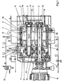
- the rotary tooth compressor shown as a whole in FIG. 1 has in a housing 1 a delivery chamber 2, in which two rotors 3, 4 are arranged. Each of these rotors 3, 4 is arranged on a pump shaft 5, 6. To both The side of the delivery chamber 2 is a pressure-tight, neutral one Room 7, 8 provided, each with a pressure medium connection 9, 10 has. Seen in Figure 1 to the left of the neutral Room 7 is located in the housing 1, a gear room 11, which is also pressure-tight and one Has pressure medium connection 12. Located in gearbox 11 there is a gear 13, which the two pump shafts 5, 6 gears together. The pump shaft 6 leads out of the gear chamber 11 and is with a motor 14 flanged to the outside of the housing 1 connected.
- the pump shafts 5, 6 penetrate with their respective right end the right, neutral room 8 and are each stored in a pedestal storage room 15, 16, which is hermetically sealed from the outside.
- the pump shafts 5, 6 are between the delivery chamber 2 and the respective neutral room 8 each with a labyrinth seal 17, 18, 19, 20 sealed.
- Shaft seals 21, 22 seal the plummer block 15, 16 compared to the neutral Room 8 onwards.
- Corresponding shaft sealing rings 23, 24 seal the neutral space 7 with respect to the gear space 11 and a shaft seal 25 opposite the gear chamber 11 the atmosphere.
- a purge gas source 31 enables the gear chamber 11 and defined the two neutral rooms 7, 8 with a purge gas To apply pressure.
- This purge gas can the neutral spaces 7, 8 via an overflow valve 32 leave. This way you can go into the neutral Evacuate rooms 7, 8 penetrating process gas continuously.
- FIG. 1 This shows compared to FIG. 1 greatly increases the shaft seals located on the pump shaft 6 22, 24, 25. All three shaft seals 22, 24, 25 have one against the pump shaft 6 Sealing lip 26, 27, 28.
- the sealing lip 28 of the Shaft sealing ring 22 points away from the delivery chamber 2.
- Figure 2 also shows that the pillow block 16 has a pressure medium connection 30 and this Pressure medium connection 30 through a line 29 to the Pressure medium connection 10 of the right neutral room 8 connected is. The left one is also connected to this line 29 neutral room 7 connected. She is connected to the Suction side of the machine stage.
Landscapes
- Engineering & Computer Science (AREA)
- Mechanical Engineering (AREA)
- General Engineering & Computer Science (AREA)
- Applications Or Details Of Rotary Compressors (AREA)
- Rotary Pumps (AREA)
- Supercharger (AREA)
- Sealing Using Fluids, Sealing Without Contact, And Removal Of Oil (AREA)
Claims (7)
- Compresseur rotatif à engrenages avec un premier carré de pompe (6) traversant un espace des engrenages (11), un espace neutre (7) et un espace de refoulement (2), et un deuxième carré de pompe (5) qui lui est parallèle et menant de l'espace des engrenages (11) en passant par l'espace neutre (7) et l'espace de refoulement (2), moyennant quoi les deux carrés de pompe (5, 6) présentent respectivement un rotor (3, 4) dans l'espace de refoulement (2), et moyennant quoi l'espace de refoulement (2) est rendu étanche par rapport à l'espace neutre (7, 8) grâce à respectivement une garniture d'étanchéité en labyrinthe (17, 18, 19, 20) pour faire passer les deux carrés de pompe (5, 6),
caractérisé en ce que
l'espace des engrenages (11) et l'espace neutre (7) sont réalisés de manière à conserver la pression et sont respectivement pourvus d'un raccordement de moyen de pression (9, 12), en ce que les deux carrés de pompe (5, 6) entre l'espace de refoulement (2) et l'espace des engrenages (11), et le carré de pompe (6) menant vers l'extérieur hors de l'espace des engrenages (11) entre l'atmosphère et l'espace des engrenages (11), sont respectivement rendus étanches grâce à une bague à lèvres avec ressort (24, 25) présentant une lèvre d'étanchéité (27, 26) reposant contre le carré de pompe (5, 6) respectif et orientée vers l'espace de refoulement (2). - Compresseur rotatif à engrenages selon la revendication 1, pour lequel les deux carrés de pompe (5, 6) sont respectivement logés dans un espace du palier support (16) sur le côté de l'espace de refoulement (2) situé en face de l'espace des engrenages (11), un espace neutre (8) étant également prévu entre l'espace du palier support (16) et l'espace de refoulement (2),
caractérisé en ce que
l'espace du palier support (15, 16) et l'espace neutre (8) situé entre lui et l'espace de refoulement (2) sont réalisés de manière à conserver la pression et sont respectivement pourvus d'un raccordement de moyen de pression (10, 30), et en ce que chaque espace du palier support (15, 16) est rendu étanche grâce à une bague à lèvres avec ressort reposant contre le carré de pompe (5, 6) avec une lèvre d'étanchéité. - Compresseur rotatif à engrenages selon l'une quelconque des revendications 1 ou 2,
caractérisé en ce que
les deux espaces neutres (7, 8) sont respectivement en liaison avec le côté d'aspiration du compresseur rotatif à engrenages. - Procédé pour le fonctionnement d'un compresseur rotatif à engrenages selon l'une quelconque des revendications précédentes,
caractérisé en ce que
l'espace neutre du côté de l'espace des engrenages est pressurisé avec une pression inférieure à la pression dans l'espace de refoulement, et en ce que l'espace des engrenages est pressurisé avec une pression inférieure à la pression dans l'espace de refoulement, mais cependant plus élevée que la pression atmosphérique. - Procédé selon la revendication 4,
caractérisé en ce que
l'espace neutre du côté de l'espace du palier support est également pressurisé avec une pression inférieure à la pression qui règne dans l'espace de refoulement. - Procédé selon la revendication 5,
caractérisé en ce que
l'espace du palier support et l'espace neutre qui le sépare de l'espace de refoulement sont raccordés à une source de moyen de pression commune. - Procédé selon l'une quelconque des revendications précédentes,
caractérisé en ce que
les espaces neutres sont en liaison avec une source de gaz de balayage pour la pressurisation, et présentent respectivement une sortie pour le gaz de balayage régulée par une soupape de décharge.
Applications Claiming Priority (2)
| Application Number | Priority Date | Filing Date | Title |
|---|---|---|---|
| DE19822283 | 1998-05-18 | ||
| DE19822283A DE19822283A1 (de) | 1998-05-18 | 1998-05-18 | Drehzahnverdichter und Verfahren zum Betrieb eines solchen |
Publications (2)
| Publication Number | Publication Date |
|---|---|
| EP0959251A1 EP0959251A1 (fr) | 1999-11-24 |
| EP0959251B1 true EP0959251B1 (fr) | 2004-05-19 |
Family
ID=7868186
Family Applications (1)
| Application Number | Title | Priority Date | Filing Date |
|---|---|---|---|
| EP99109591A Expired - Lifetime EP0959251B1 (fr) | 1998-05-18 | 1999-05-14 | Compresseur rotatif à engrenages et procédé pour son fonctionnement |
Country Status (3)
| Country | Link |
|---|---|
| EP (1) | EP0959251B1 (fr) |
| AT (1) | ATE267346T1 (fr) |
| DE (2) | DE19822283A1 (fr) |
Cited By (1)
| Publication number | Priority date | Publication date | Assignee | Title |
|---|---|---|---|---|
| CN108138646A (zh) * | 2015-08-25 | 2018-06-08 | 伊顿智能动力有限公司 | 用于增压器的高压转子密封构造 |
Families Citing this family (5)
| Publication number | Priority date | Publication date | Assignee | Title |
|---|---|---|---|---|
| JP4061850B2 (ja) * | 2001-02-28 | 2008-03-19 | 株式会社豊田自動織機 | 真空ポンプにおける軸封構造 |
| CN100400881C (zh) * | 2002-08-23 | 2008-07-09 | 株式会社丰田自动织机 | 具有轴密封结构的真空泵 |
| WO2007065484A1 (fr) | 2005-12-08 | 2007-06-14 | Ghh Rand Schraubenkompressoren Gmbh | Compresseur à vis |
| ITVI20130021A1 (it) * | 2013-01-31 | 2013-05-02 | Virgilio Mietto | Compressore volumetrico dotato di un sistema di lubrificazione migliorato. |
| FR3148459B1 (fr) * | 2023-05-02 | 2025-04-25 | Pfeiffer Vacuum | Pompe à vide |
Family Cites Families (9)
| Publication number | Priority date | Publication date | Assignee | Title |
|---|---|---|---|---|
| GB559226A (en) * | 1942-08-07 | 1944-02-09 | Douglas Rudolf Pobjoy | Improvements in and relating to rotary pumps |
| IT1155126B (it) * | 1982-03-10 | 1987-01-21 | Fiat Auto Spa | Compressore volumetrico rotativo del tipo roots |
| US4755115A (en) * | 1984-11-21 | 1988-07-05 | Atsugi Motor Parts Company, Limited | Shaft seal assembly for compressor |
| JPH05296171A (ja) * | 1992-04-13 | 1993-11-09 | Ulvac Japan Ltd | 封液を用いない容積型真空ポンプの軸シール機構 |
| DE4301293C2 (de) * | 1993-01-15 | 1996-07-11 | Mannesmann Ag | Vorrichtung zum Entfernen kleiner Schmier- und Kühlflüssigkeitsleckagemengen |
| DE29506010U1 (de) * | 1995-04-07 | 1996-08-08 | Armatec FTS-Armaturen GmbH & Co KG, 88239 Wangen | Drehkolbenpumpe |
| JP3493850B2 (ja) * | 1995-11-22 | 2004-02-03 | 石川島播磨重工業株式会社 | 機械駆動式過給機のシール構造 |
| DE19626515A1 (de) * | 1996-07-02 | 1998-01-08 | Ghh Borsig Turbomaschinen Gmbh | Sperrflüssigkeitsabdichtung eines ölfreien Schraubenverdichters |
| DE19633651A1 (de) * | 1996-08-21 | 1998-02-26 | Leybold Vakuum Gmbh | Trockene Vakuummaschine mit Wellendurchführung |
-
1998
- 1998-05-18 DE DE19822283A patent/DE19822283A1/de not_active Withdrawn
-
1999
- 1999-05-14 DE DE59909504T patent/DE59909504D1/de not_active Expired - Fee Related
- 1999-05-14 AT AT99109591T patent/ATE267346T1/de not_active IP Right Cessation
- 1999-05-14 EP EP99109591A patent/EP0959251B1/fr not_active Expired - Lifetime
Cited By (1)
| Publication number | Priority date | Publication date | Assignee | Title |
|---|---|---|---|---|
| CN108138646A (zh) * | 2015-08-25 | 2018-06-08 | 伊顿智能动力有限公司 | 用于增压器的高压转子密封构造 |
Also Published As
| Publication number | Publication date |
|---|---|
| DE19822283A1 (de) | 1999-11-25 |
| DE59909504D1 (de) | 2004-06-24 |
| ATE267346T1 (de) | 2004-06-15 |
| EP0959251A1 (fr) | 1999-11-24 |
Similar Documents
| Publication | Publication Date | Title |
|---|---|---|
| DE60113894T2 (de) | Dichtungsanordnungen | |
| DE3781482T2 (de) | Vakuumerzeugungssystem. | |
| DE69312738T2 (de) | Rotierender schraubenverdichter mit wellenabdichtung | |
| DE68905026T2 (de) | Mehrstufige roots-vakuumpumpe. | |
| DE2441520A1 (de) | Wellendichtung fuer schraubenrotorverdichter | |
| DE69614225T2 (de) | Abdichtung eines brennkraftmaschinen getriebenen Laders | |
| WO1998039570A1 (fr) | Pompe a vide | |
| CH684495A5 (de) | Turbomaschine. | |
| DE69421395T2 (de) | Abdichtungssystem | |
| EP0959251B1 (fr) | Compresseur rotatif à engrenages et procédé pour son fonctionnement | |
| DE10003018B4 (de) | Turboverdichter | |
| DE69005230T2 (de) | Öldichtung für drehende Vakuumpumpe. | |
| CH628709A5 (en) | Roots pump | |
| DE102006020710A1 (de) | Vakuumpumpe mit Gehäuse | |
| EP3371458B1 (fr) | Pompe à vide sèche | |
| DE1939717A1 (de) | Waelzkolbenpumpe | |
| DE3617889C2 (fr) | ||
| DE60104329T2 (de) | Wellenabdichtung | |
| DE8415459U1 (de) | Rotorwellen-lagervorrichtung fuer einen drehkolbenkompressor | |
| DE2539168C2 (de) | Einrichtung an Kreiselgebläsen | |
| EP0990798A1 (fr) | Turbo-compresseur | |
| DE3817617A1 (de) | Abgasturbolader fuer eine brennkraftmaschine | |
| EP0198936B1 (fr) | Pompe à vide multiétagée | |
| DE1528974A1 (de) | Pumpe,insbesondere Zahnradpumpe | |
| DE2639127A1 (de) | Drehkolbenvorrichtung |
Legal Events
| Date | Code | Title | Description |
|---|---|---|---|
| PUAI | Public reference made under article 153(3) epc to a published international application that has entered the european phase |
Free format text: ORIGINAL CODE: 0009012 |
|
| AK | Designated contracting states |
Kind code of ref document: A1 Designated state(s): AT BE CH CY DE DK ES FI FR GB GR IE IT LI LU MC NL |
|
| AX | Request for extension of the european patent |
Free format text: AL;LT;LV;MK;RO;SI |
|
| 17P | Request for examination filed |
Effective date: 20000517 |
|
| AKX | Designation fees paid |
Free format text: AT BE CH CY DE DK ES FI FR GB GR IE IT LI LU MC NL |
|
| RBV | Designated contracting states (corrected) |
Designated state(s): AT BE CH DE DK ES FI FR GB GR IE IT LI LU NL PT SE |
|
| GRAP | Despatch of communication of intention to grant a patent |
Free format text: ORIGINAL CODE: EPIDOSNIGR1 |
|
| GRAS | Grant fee paid |
Free format text: ORIGINAL CODE: EPIDOSNIGR3 |
|
| GRAA | (expected) grant |
Free format text: ORIGINAL CODE: 0009210 |
|
| AK | Designated contracting states |
Kind code of ref document: B1 Designated state(s): AT BE CH DE DK ES FI FR GB GR IE IT LI LU NL PT SE |
|
| PG25 | Lapsed in a contracting state [announced via postgrant information from national office to epo] |
Ref country code: NL Free format text: LAPSE BECAUSE OF FAILURE TO SUBMIT A TRANSLATION OF THE DESCRIPTION OR TO PAY THE FEE WITHIN THE PRESCRIBED TIME-LIMIT Effective date: 20040519 Ref country code: IT Free format text: LAPSE BECAUSE OF FAILURE TO SUBMIT A TRANSLATION OF THE DESCRIPTION OR TO PAY THE FEE WITHIN THE PRESCRIBED TIME-LIMIT;WARNING: LAPSES OF ITALIAN PATENTS WITH EFFECTIVE DATE BEFORE 2007 MAY HAVE OCCURRED AT ANY TIME BEFORE 2007. THE CORRECT EFFECTIVE DATE MAY BE DIFFERENT FROM THE ONE RECORDED. Effective date: 20040519 Ref country code: IE Free format text: LAPSE BECAUSE OF FAILURE TO SUBMIT A TRANSLATION OF THE DESCRIPTION OR TO PAY THE FEE WITHIN THE PRESCRIBED TIME-LIMIT Effective date: 20040519 Ref country code: GB Free format text: LAPSE BECAUSE OF FAILURE TO SUBMIT A TRANSLATION OF THE DESCRIPTION OR TO PAY THE FEE WITHIN THE PRESCRIBED TIME-LIMIT Effective date: 20040519 Ref country code: FR Free format text: LAPSE BECAUSE OF FAILURE TO SUBMIT A TRANSLATION OF THE DESCRIPTION OR TO PAY THE FEE WITHIN THE PRESCRIBED TIME-LIMIT Effective date: 20040519 Ref country code: FI Free format text: LAPSE BECAUSE OF FAILURE TO SUBMIT A TRANSLATION OF THE DESCRIPTION OR TO PAY THE FEE WITHIN THE PRESCRIBED TIME-LIMIT Effective date: 20040519 |
|
| REG | Reference to a national code |
Ref country code: GB Ref legal event code: FG4D Free format text: NOT ENGLISH |
|
| REG | Reference to a national code |
Ref country code: CH Ref legal event code: EP |
|
| REG | Reference to a national code |
Ref country code: IE Ref legal event code: FG4D Free format text: GERMAN |
|
| REF | Corresponds to: |
Ref document number: 59909504 Country of ref document: DE Date of ref document: 20040624 Kind code of ref document: P |
|
| REG | Reference to a national code |
Ref country code: CH Ref legal event code: NV Representative=s name: PPS POLYVALENT PATENT SERVICE AG |
|
| PG25 | Lapsed in a contracting state [announced via postgrant information from national office to epo] |
Ref country code: SE Free format text: LAPSE BECAUSE OF FAILURE TO SUBMIT A TRANSLATION OF THE DESCRIPTION OR TO PAY THE FEE WITHIN THE PRESCRIBED TIME-LIMIT Effective date: 20040819 Ref country code: GR Free format text: LAPSE BECAUSE OF FAILURE TO SUBMIT A TRANSLATION OF THE DESCRIPTION OR TO PAY THE FEE WITHIN THE PRESCRIBED TIME-LIMIT Effective date: 20040819 Ref country code: DK Free format text: LAPSE BECAUSE OF FAILURE TO SUBMIT A TRANSLATION OF THE DESCRIPTION OR TO PAY THE FEE WITHIN THE PRESCRIBED TIME-LIMIT Effective date: 20040819 |
|
| PG25 | Lapsed in a contracting state [announced via postgrant information from national office to epo] |
Ref country code: ES Free format text: LAPSE BECAUSE OF FAILURE TO SUBMIT A TRANSLATION OF THE DESCRIPTION OR TO PAY THE FEE WITHIN THE PRESCRIBED TIME-LIMIT Effective date: 20040830 |
|
| NLV1 | Nl: lapsed or annulled due to failure to fulfill the requirements of art. 29p and 29m of the patents act | ||
| GBV | Gb: ep patent (uk) treated as always having been void in accordance with gb section 77(7)/1977 [no translation filed] |
Effective date: 20040519 |
|
| REG | Reference to a national code |
Ref country code: IE Ref legal event code: FD4D |
|
| PLBE | No opposition filed within time limit |
Free format text: ORIGINAL CODE: 0009261 |
|
| STAA | Information on the status of an ep patent application or granted ep patent |
Free format text: STATUS: NO OPPOSITION FILED WITHIN TIME LIMIT |
|
| 26N | No opposition filed |
Effective date: 20050222 |
|
| EN | Fr: translation not filed | ||
| PG25 | Lapsed in a contracting state [announced via postgrant information from national office to epo] |
Ref country code: LU Free format text: LAPSE BECAUSE OF NON-PAYMENT OF DUE FEES Effective date: 20050514 |
|
| PG25 | Lapsed in a contracting state [announced via postgrant information from national office to epo] |
Ref country code: BE Free format text: LAPSE BECAUSE OF NON-PAYMENT OF DUE FEES Effective date: 20050531 |
|
| BERE | Be: lapsed |
Owner name: *SGI-PROZESS-TECHNIK G.M.B.H. Effective date: 20050531 |
|
| BERE | Be: lapsed |
Owner name: *SGI-PROZESS-TECHNIK G.M.B.H. Effective date: 20050531 |
|
| PG25 | Lapsed in a contracting state [announced via postgrant information from national office to epo] |
Ref country code: PT Free format text: LAPSE BECAUSE OF NON-PAYMENT OF DUE FEES Effective date: 20041019 |
|
| PGFP | Annual fee paid to national office [announced via postgrant information from national office to epo] |
Ref country code: AT Payment date: 20080410 Year of fee payment: 10 |
|
| PGFP | Annual fee paid to national office [announced via postgrant information from national office to epo] |
Ref country code: DE Payment date: 20090525 Year of fee payment: 11 |
|
| PGFP | Annual fee paid to national office [announced via postgrant information from national office to epo] |
Ref country code: CH Payment date: 20090518 Year of fee payment: 11 |
|
| PG25 | Lapsed in a contracting state [announced via postgrant information from national office to epo] |
Ref country code: AT Free format text: LAPSE BECAUSE OF NON-PAYMENT OF DUE FEES Effective date: 20090514 |
|
| REG | Reference to a national code |
Ref country code: CH Ref legal event code: PL |
|
| PG25 | Lapsed in a contracting state [announced via postgrant information from national office to epo] |
Ref country code: LI Free format text: LAPSE BECAUSE OF NON-PAYMENT OF DUE FEES Effective date: 20100531 Ref country code: CH Free format text: LAPSE BECAUSE OF NON-PAYMENT OF DUE FEES Effective date: 20100531 |
|
| PG25 | Lapsed in a contracting state [announced via postgrant information from national office to epo] |
Ref country code: DE Free format text: LAPSE BECAUSE OF NON-PAYMENT OF DUE FEES Effective date: 20101201 |