EP0959276B1 - Garniture mécanique d'étanchéité - Google Patents
Garniture mécanique d'étanchéité Download PDFInfo
- Publication number
- EP0959276B1 EP0959276B1 EP19990105834 EP99105834A EP0959276B1 EP 0959276 B1 EP0959276 B1 EP 0959276B1 EP 19990105834 EP19990105834 EP 19990105834 EP 99105834 A EP99105834 A EP 99105834A EP 0959276 B1 EP0959276 B1 EP 0959276B1
- Authority
- EP
- European Patent Office
- Prior art keywords
- ring
- mechanical seal
- machine part
- ducts
- rear surface
- Prior art date
- Legal status (The legal status is an assumption and is not a legal conclusion. Google has not performed a legal analysis and makes no representation as to the accuracy of the status listed.)
- Expired - Lifetime
Links
- 230000002706 hydrostatic effect Effects 0.000 claims description 4
- 238000010276 construction Methods 0.000 description 3
- 238000007789 sealing Methods 0.000 description 2
- 229910001018 Cast iron Inorganic materials 0.000 description 1
- 229910000831 Steel Inorganic materials 0.000 description 1
- 230000004323 axial length Effects 0.000 description 1
- 238000001816 cooling Methods 0.000 description 1
- 238000006073 displacement reaction Methods 0.000 description 1
- 239000000428 dust Substances 0.000 description 1
- 238000009434 installation Methods 0.000 description 1
- 239000011499 joint compound Substances 0.000 description 1
- 238000009931 pascalization Methods 0.000 description 1
- 239000004576 sand Substances 0.000 description 1
- 239000010959 steel Substances 0.000 description 1
- 239000004575 stone Substances 0.000 description 1
Images
Classifications
-
- F—MECHANICAL ENGINEERING; LIGHTING; HEATING; WEAPONS; BLASTING
- F16—ENGINEERING ELEMENTS AND UNITS; GENERAL MEASURES FOR PRODUCING AND MAINTAINING EFFECTIVE FUNCTIONING OF MACHINES OR INSTALLATIONS; THERMAL INSULATION IN GENERAL
- F16J—PISTONS; CYLINDERS; SEALINGS
- F16J15/00—Sealings
- F16J15/16—Sealings between relatively-moving surfaces
- F16J15/34—Sealings between relatively-moving surfaces with slip-ring pressed against a more or less radial face on one member
- F16J15/3436—Pressing means
- F16J15/344—Pressing means the pressing force being applied by means of an elastic ring supporting the slip-ring
Definitions
- the invention relates to a Device with two machine parts, which by means of a Mechanical seal are sealed, the Mechanical seal consisting of a non-rotating and a circumferential slide ring, each with a clamping surface for receiving an elastic O-ring exists, which in the installed state between the clamping surface and a corresponding one Surface of a machine part extends so that a friction Torque protection is generated, the clamping surface of at least one slide ring and the corresponding surface of the machine part is rectangular in cross section is designed so that the O-ring in the installed position on an axial and Radial surface of the machine part rests.
- the mechanical seal essentially consists of two mechanical seals of different geometrical shapes, which are arranged in the machine part by means of diagonally opposite O-rings. Such sealing systems are referred to as asymmetrical mechanical seals.
- Modern drive axles of construction machines equipped with wet multi-disc brakes are generally sealed with asymmetrical mechanical seals.
- higher performance requirements for the axles now require reinforced braking systems. To cool them, cooling oil must be available under increased pressure and in large quantities. A permanent pressure of 2.5 bar, which can rise to 25 bar depending on the application, is used in such new designs.
- the invention has for its object a pressure-relieved asymmetrical To provide a mechanical seal in such a device that is shorter than known in the axial direction Mechanical seals are formed.
- the axial length of the corresponding groove of the machine part only needs to correspond approximately to the thickness of the O-ring. Since the O-ring can be supported on the radial surface of the machine part, the O-rings with smaller diameters are used, so that in total one becomes axial short mechanical seal created.
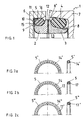
- the mechanical seal 1 shown in Figure 1 consists of a rotationally fixed slide ring 2 and a circumferential slide ring 3, which acts as a counter ring. Both mechanical rings 2, 3 consist of wear-resistant cast iron and, together with two elastic O-rings 4, 5, form a mechanical seal for installation in a construction machine. In the drawing, only the machine parts 6, 7 receiving the mechanical seal 1 are indicated.
- the mechanical seal 1 is an asymmetrical mechanical seal, since the mechanical rings 2, 3 have a different geometric contour.
- the slide ring 3 has a conical clamping surface 8 and in the machine part 7 also a corresponding clamping surface 8 '.
- the stationary sliding ring 2 has a cylindrical clamping surface 9 and interacts with an O-ring 5 with a smaller diameter than the O-ring 4 of the sliding ring 3 ,
- the O-ring 5 is supported in the machine part 6 on a radial surface 10 and an axial surface 11.
- the mechanical seal is under hydrostatic pressure in the area below the sealing surface 12 in the space 13 to be sealed. The pressure is symbolized by arrows.
- the O-ring 5.5 ′, 5 ′′ is provided with channels 14, 14 ′, 14 ′′, which exert the hydrostatic pressure on the back surface 15 up to that through the axial surface 11 and O-ring 5.5 ', 5''formed pressure relief line 16. In this way, the mechanical seal is relieved of pressure.
- the channels 14, 14 ', 14'' can be produced by recesses as shown in FIG. 2a or, as in FIGS. 2b and 2c, by knob-like projections 17, 17' of different geometries.
Landscapes
- Engineering & Computer Science (AREA)
- General Engineering & Computer Science (AREA)
- Mechanical Engineering (AREA)
- Mechanical Sealing (AREA)
Claims (3)
- Dispositif comprenant deux pièces de machine (6, 7), qui sont étanchéifiées au moyen d'une garniture d'étanchéité à anneau de glissement, la garniture d'étanchéité à anneau de glissement comprenant un anneau de glissement fixe en rotation (2) et un anneau de glissement rotatif (3) ayant chacun une surface de serrage pour la réception d'un anneau torique élastique (4, 5), qui, à l'état monté, s'étend entre la surface de serrage (8, 9) et une surface correspondante (8') d'une pièce de machine (7), de telle sorte que par friction une sécurité de couple est obtenue, la surface de serrage (9) d'au moins un anneau de glissement (2) et la surface correspondante de la pièce de machine étant réalisées avec une section transversale rectangulaire de telle sorte que l'anneau torique (5) dans la position montée repose contre une surface axiale (11) et une surface radiale (10) de la pièce de machine (6), caractérisé en ce que l'anneau torique (5) comprend sur sa surface arrière (15) tournée vers la surface radiale (10) des canaux (14, 14', 14"), qui permettent de transmettre la pression hydrostatique régnant en fonctionnement sur des parties de la surface arrière (10) et jusqu'à la ligne de limitation de pression (16) formée par la surface axiale (11) et l'anneau torique (5).
- Dispositif selon la revendication 1, caractérisé en ce que les canaux (14') sont formés par plusieurs évidements orientés radialement situés sur la surface arrière (15) de l'anneau torique (5').
- Dispositif selon la revendication 1, caractérisé en ce que les canaux (14, 14") sont formés par plusieurs projections orientées axialement (17, 17') situées sur la surface arrière (15) de l'anneau torique (5, 5").
Applications Claiming Priority (2)
| Application Number | Priority Date | Filing Date | Title |
|---|---|---|---|
| DE19822356 | 1998-05-19 | ||
| DE1998122356 DE19822356C1 (de) | 1998-05-19 | 1998-05-19 | Gleitringdichtung |
Publications (3)
| Publication Number | Publication Date |
|---|---|
| EP0959276A2 EP0959276A2 (fr) | 1999-11-24 |
| EP0959276A3 EP0959276A3 (fr) | 2000-09-06 |
| EP0959276B1 true EP0959276B1 (fr) | 2004-05-06 |
Family
ID=7868233
Family Applications (1)
| Application Number | Title | Priority Date | Filing Date |
|---|---|---|---|
| EP19990105834 Expired - Lifetime EP0959276B1 (fr) | 1998-05-19 | 1999-03-23 | Garniture mécanique d'étanchéité |
Country Status (2)
| Country | Link |
|---|---|
| EP (1) | EP0959276B1 (fr) |
| DE (1) | DE19822356C1 (fr) |
Family Cites Families (6)
| Publication number | Priority date | Publication date | Assignee | Title |
|---|---|---|---|---|
| FR1047464A (fr) * | 1952-01-03 | 1953-12-15 | Perfectionnements aux dispositifs d'étanchéité pour sorties d'arbres | |
| US3542377A (en) * | 1968-03-18 | 1970-11-24 | Rex Chainbelt Inc | Secondary seal with sprags |
| US4083569A (en) * | 1974-01-21 | 1978-04-11 | Giorgio Negro | Frontal seal, in particular for tracked vehicles |
| US3905607A (en) * | 1974-02-08 | 1975-09-16 | Caterpillar Tractor Co | Face-type sealing ring with inner seal band |
| JPS589870B2 (ja) * | 1975-08-30 | 1983-02-23 | エヌオーケー株式会社 | メカニカルシ−ル |
| DE4443448C2 (de) * | 1994-12-07 | 1998-10-29 | Ae Goetze Gmbh | Gleitringdichtung |
-
1998
- 1998-05-19 DE DE1998122356 patent/DE19822356C1/de not_active Expired - Fee Related
-
1999
- 1999-03-23 EP EP19990105834 patent/EP0959276B1/fr not_active Expired - Lifetime
Also Published As
| Publication number | Publication date |
|---|---|
| DE19822356C1 (de) | 1999-12-23 |
| EP0959276A2 (fr) | 1999-11-24 |
| EP0959276A3 (fr) | 2000-09-06 |
Similar Documents
| Publication | Publication Date | Title |
|---|---|---|
| EP1071896B1 (fr) | Element d'etancheite destine a un systeme d'etancheite a anneau de glissement | |
| DE19713455B4 (de) | Dichtring | |
| DE69403135T2 (de) | Universaler Segmenttreibbelag für Kupplungen | |
| DE69935834T2 (de) | Hydrodynamische Dichtung für kompressible Medien | |
| DE102007044856B4 (de) | Kupplungsanordnung mit einer Kupplungsscheibe mit inneren Fluidkanälen | |
| DE3238158A1 (de) | Lagerdichtung | |
| DE3039678A1 (de) | Gasdichtungsbuchse | |
| DE19518577A1 (de) | Radialwellendichtring | |
| EP0992722B1 (fr) | Garniture mécanique d'étanchéité | |
| DE3727023A1 (de) | Gleitringabdichtung | |
| DE3118469A1 (de) | "fluiddichtung" | |
| EP3217031A1 (fr) | Embrayage à disque | |
| DE2164418A1 (de) | Scheibenbremse | |
| DE4443448C2 (de) | Gleitringdichtung | |
| DE3319729C2 (de) | Kolbenringanordnung für Hydraulikanwendungen, insbesondere für sehr hohe Betriebsdrücke | |
| DE3521525C1 (de) | Dichtungsanordnung | |
| EP0959276B1 (fr) | Garniture mécanique d'étanchéité | |
| EP4067706A1 (fr) | Bague d'étanchéité | |
| EP0656462B1 (fr) | Dispositif d'étanchéité | |
| EP0369131B1 (fr) | Bagues à lèvres radiales | |
| EP2535621B1 (fr) | Joint d'étanchéité pour arbre pour un système d'huile de blocage d'un générateur refroidi à l'hydrogène | |
| EP0992723A2 (fr) | Joint d'étanchéité à jeu d'étranglement pour fluides gazeux | |
| AT518017B1 (de) | Reiblamelle | |
| WO1999060283A1 (fr) | Accouplement d'arbre elastique | |
| EP3417192B1 (fr) | Joint d'arbre |
Legal Events
| Date | Code | Title | Description |
|---|---|---|---|
| PUAI | Public reference made under article 153(3) epc to a published international application that has entered the european phase |
Free format text: ORIGINAL CODE: 0009012 |
|
| AK | Designated contracting states |
Kind code of ref document: A2 Designated state(s): FR GB IT SE |
|
| AX | Request for extension of the european patent |
Free format text: AL;LT;LV;MK;RO;SI |
|
| PUAL | Search report despatched |
Free format text: ORIGINAL CODE: 0009013 |
|
| AK | Designated contracting states |
Kind code of ref document: A3 Designated state(s): AT BE CH CY DE DK ES FI FR GB GR IE IT LI LU MC NL PT SE |
|
| AX | Request for extension of the european patent |
Free format text: AL;LT;LV;MK;RO;SI |
|
| 17P | Request for examination filed |
Effective date: 20010221 |
|
| AKX | Designation fees paid |
Free format text: FR GB IT SE |
|
| GRAP | Despatch of communication of intention to grant a patent |
Free format text: ORIGINAL CODE: EPIDOSNIGR1 |
|
| RIN1 | Information on inventor provided before grant (corrected) |
Inventor name: DENGLER, ANDREAS, DIPL.-ING. Inventor name: ZUTZ, HANS-HENNING |
|
| REG | Reference to a national code |
Ref country code: DE Ref legal event code: 8566 |
|
| GRAS | Grant fee paid |
Free format text: ORIGINAL CODE: EPIDOSNIGR3 |
|
| GRAA | (expected) grant |
Free format text: ORIGINAL CODE: 0009210 |
|
| AK | Designated contracting states |
Kind code of ref document: B1 Designated state(s): FR GB IT SE |
|
| REG | Reference to a national code |
Ref country code: GB Ref legal event code: FG4D Free format text: NOT ENGLISH |
|
| GBT | Gb: translation of ep patent filed (gb section 77(6)(a)/1977) |
Effective date: 20040615 |
|
| REG | Reference to a national code |
Ref country code: SE Ref legal event code: TRGR |
|
| ET | Fr: translation filed | ||
| PGFP | Annual fee paid to national office [announced via postgrant information from national office to epo] |
Ref country code: GB Payment date: 20050207 Year of fee payment: 7 |
|
| PGFP | Annual fee paid to national office [announced via postgrant information from national office to epo] |
Ref country code: FR Payment date: 20050302 Year of fee payment: 7 |
|
| PGFP | Annual fee paid to national office [announced via postgrant information from national office to epo] |
Ref country code: SE Payment date: 20050303 Year of fee payment: 7 |
|
| PLBE | No opposition filed within time limit |
Free format text: ORIGINAL CODE: 0009261 |
|
| STAA | Information on the status of an ep patent application or granted ep patent |
Free format text: STATUS: NO OPPOSITION FILED WITHIN TIME LIMIT |
|
| 26N | No opposition filed |
Effective date: 20050208 |
|
| PG25 | Lapsed in a contracting state [announced via postgrant information from national office to epo] |
Ref country code: GB Free format text: LAPSE BECAUSE OF NON-PAYMENT OF DUE FEES Effective date: 20060323 |
|
| PG25 | Lapsed in a contracting state [announced via postgrant information from national office to epo] |
Ref country code: SE Free format text: LAPSE BECAUSE OF NON-PAYMENT OF DUE FEES Effective date: 20060324 |
|
| PGFP | Annual fee paid to national office [announced via postgrant information from national office to epo] |
Ref country code: IT Payment date: 20060331 Year of fee payment: 8 |
|
| EUG | Se: european patent has lapsed | ||
| GBPC | Gb: european patent ceased through non-payment of renewal fee |
Effective date: 20060323 |
|
| REG | Reference to a national code |
Ref country code: FR Ref legal event code: ST Effective date: 20061130 |
|
| PG25 | Lapsed in a contracting state [announced via postgrant information from national office to epo] |
Ref country code: FR Free format text: LAPSE BECAUSE OF NON-PAYMENT OF DUE FEES Effective date: 20060331 |
|
| PG25 | Lapsed in a contracting state [announced via postgrant information from national office to epo] |
Ref country code: IT Free format text: LAPSE BECAUSE OF NON-PAYMENT OF DUE FEES Effective date: 20070323 |