EP0959292A2 - Gasarmatur - Google Patents
Gasarmatur Download PDFInfo
- Publication number
- EP0959292A2 EP0959292A2 EP98118966A EP98118966A EP0959292A2 EP 0959292 A2 EP0959292 A2 EP 0959292A2 EP 98118966 A EP98118966 A EP 98118966A EP 98118966 A EP98118966 A EP 98118966A EP 0959292 A2 EP0959292 A2 EP 0959292A2
- Authority
- EP
- European Patent Office
- Prior art keywords
- gas
- pressure
- shut
- ring
- gas valve
- Prior art date
- Legal status (The legal status is an assumption and is not a legal conclusion. Google has not performed a legal analysis and makes no representation as to the accuracy of the status listed.)
- Granted
Links
Images


Classifications
-
- F—MECHANICAL ENGINEERING; LIGHTING; HEATING; WEAPONS; BLASTING
- F17—STORING OR DISTRIBUTING GASES OR LIQUIDS
- F17C—VESSELS FOR CONTAINING OR STORING COMPRESSED, LIQUEFIED OR SOLIDIFIED GASES; FIXED-CAPACITY GAS-HOLDERS; FILLING VESSELS WITH, OR DISCHARGING FROM VESSELS, COMPRESSED, LIQUEFIED, OR SOLIDIFIED GASES
- F17C13/00—Details of vessels or of the filling or discharging of vessels
- F17C13/04—Arrangement or mounting of valves
-
- F—MECHANICAL ENGINEERING; LIGHTING; HEATING; WEAPONS; BLASTING
- F17—STORING OR DISTRIBUTING GASES OR LIQUIDS
- F17C—VESSELS FOR CONTAINING OR STORING COMPRESSED, LIQUEFIED OR SOLIDIFIED GASES; FIXED-CAPACITY GAS-HOLDERS; FILLING VESSELS WITH, OR DISCHARGING FROM VESSELS, COMPRESSED, LIQUEFIED, OR SOLIDIFIED GASES
- F17C2201/00—Vessel construction, in particular geometry, arrangement or size
- F17C2201/01—Shape
- F17C2201/0104—Shape cylindrical
- F17C2201/0109—Shape cylindrical with exteriorly curved end-piece
-
- F—MECHANICAL ENGINEERING; LIGHTING; HEATING; WEAPONS; BLASTING
- F17—STORING OR DISTRIBUTING GASES OR LIQUIDS
- F17C—VESSELS FOR CONTAINING OR STORING COMPRESSED, LIQUEFIED OR SOLIDIFIED GASES; FIXED-CAPACITY GAS-HOLDERS; FILLING VESSELS WITH, OR DISCHARGING FROM VESSELS, COMPRESSED, LIQUEFIED, OR SOLIDIFIED GASES
- F17C2201/00—Vessel construction, in particular geometry, arrangement or size
- F17C2201/01—Shape
- F17C2201/0104—Shape cylindrical
- F17C2201/0119—Shape cylindrical with flat end-piece
-
- F—MECHANICAL ENGINEERING; LIGHTING; HEATING; WEAPONS; BLASTING
- F17—STORING OR DISTRIBUTING GASES OR LIQUIDS
- F17C—VESSELS FOR CONTAINING OR STORING COMPRESSED, LIQUEFIED OR SOLIDIFIED GASES; FIXED-CAPACITY GAS-HOLDERS; FILLING VESSELS WITH, OR DISCHARGING FROM VESSELS, COMPRESSED, LIQUEFIED, OR SOLIDIFIED GASES
- F17C2205/00—Vessel construction, in particular mounting arrangements, attachments or identifications means
- F17C2205/03—Fluid connections, filters, valves, closure means or other attachments
- F17C2205/0302—Fittings, valves, filters, or components in connection with the gas storage device
- F17C2205/0323—Valves
-
- F—MECHANICAL ENGINEERING; LIGHTING; HEATING; WEAPONS; BLASTING
- F17—STORING OR DISTRIBUTING GASES OR LIQUIDS
- F17C—VESSELS FOR CONTAINING OR STORING COMPRESSED, LIQUEFIED OR SOLIDIFIED GASES; FIXED-CAPACITY GAS-HOLDERS; FILLING VESSELS WITH, OR DISCHARGING FROM VESSELS, COMPRESSED, LIQUEFIED, OR SOLIDIFIED GASES
- F17C2205/00—Vessel construction, in particular mounting arrangements, attachments or identifications means
- F17C2205/03—Fluid connections, filters, valves, closure means or other attachments
- F17C2205/0302—Fittings, valves, filters, or components in connection with the gas storage device
- F17C2205/0338—Pressure regulators
-
- F—MECHANICAL ENGINEERING; LIGHTING; HEATING; WEAPONS; BLASTING
- F17—STORING OR DISTRIBUTING GASES OR LIQUIDS
- F17C—VESSELS FOR CONTAINING OR STORING COMPRESSED, LIQUEFIED OR SOLIDIFIED GASES; FIXED-CAPACITY GAS-HOLDERS; FILLING VESSELS WITH, OR DISCHARGING FROM VESSELS, COMPRESSED, LIQUEFIED, OR SOLIDIFIED GASES
- F17C2205/00—Vessel construction, in particular mounting arrangements, attachments or identifications means
- F17C2205/03—Fluid connections, filters, valves, closure means or other attachments
- F17C2205/0302—Fittings, valves, filters, or components in connection with the gas storage device
- F17C2205/0382—Constructional details of valves, regulators
-
- F—MECHANICAL ENGINEERING; LIGHTING; HEATING; WEAPONS; BLASTING
- F17—STORING OR DISTRIBUTING GASES OR LIQUIDS
- F17C—VESSELS FOR CONTAINING OR STORING COMPRESSED, LIQUEFIED OR SOLIDIFIED GASES; FIXED-CAPACITY GAS-HOLDERS; FILLING VESSELS WITH, OR DISCHARGING FROM VESSELS, COMPRESSED, LIQUEFIED, OR SOLIDIFIED GASES
- F17C2221/00—Handled fluid, in particular type of fluid
- F17C2221/01—Pure fluids
- F17C2221/011—Oxygen
-
- F—MECHANICAL ENGINEERING; LIGHTING; HEATING; WEAPONS; BLASTING
- F17—STORING OR DISTRIBUTING GASES OR LIQUIDS
- F17C—VESSELS FOR CONTAINING OR STORING COMPRESSED, LIQUEFIED OR SOLIDIFIED GASES; FIXED-CAPACITY GAS-HOLDERS; FILLING VESSELS WITH, OR DISCHARGING FROM VESSELS, COMPRESSED, LIQUEFIED, OR SOLIDIFIED GASES
- F17C2221/00—Handled fluid, in particular type of fluid
- F17C2221/01—Pure fluids
- F17C2221/012—Hydrogen
-
- F—MECHANICAL ENGINEERING; LIGHTING; HEATING; WEAPONS; BLASTING
- F17—STORING OR DISTRIBUTING GASES OR LIQUIDS
- F17C—VESSELS FOR CONTAINING OR STORING COMPRESSED, LIQUEFIED OR SOLIDIFIED GASES; FIXED-CAPACITY GAS-HOLDERS; FILLING VESSELS WITH, OR DISCHARGING FROM VESSELS, COMPRESSED, LIQUEFIED, OR SOLIDIFIED GASES
- F17C2221/00—Handled fluid, in particular type of fluid
- F17C2221/01—Pure fluids
- F17C2221/013—Carbon dioxide
-
- F—MECHANICAL ENGINEERING; LIGHTING; HEATING; WEAPONS; BLASTING
- F17—STORING OR DISTRIBUTING GASES OR LIQUIDS
- F17C—VESSELS FOR CONTAINING OR STORING COMPRESSED, LIQUEFIED OR SOLIDIFIED GASES; FIXED-CAPACITY GAS-HOLDERS; FILLING VESSELS WITH, OR DISCHARGING FROM VESSELS, COMPRESSED, LIQUEFIED, OR SOLIDIFIED GASES
- F17C2221/00—Handled fluid, in particular type of fluid
- F17C2221/01—Pure fluids
- F17C2221/014—Nitrogen
-
- F—MECHANICAL ENGINEERING; LIGHTING; HEATING; WEAPONS; BLASTING
- F17—STORING OR DISTRIBUTING GASES OR LIQUIDS
- F17C—VESSELS FOR CONTAINING OR STORING COMPRESSED, LIQUEFIED OR SOLIDIFIED GASES; FIXED-CAPACITY GAS-HOLDERS; FILLING VESSELS WITH, OR DISCHARGING FROM VESSELS, COMPRESSED, LIQUEFIED, OR SOLIDIFIED GASES
- F17C2221/00—Handled fluid, in particular type of fluid
- F17C2221/01—Pure fluids
- F17C2221/016—Noble gases (Ar, Kr, Xe)
-
- F—MECHANICAL ENGINEERING; LIGHTING; HEATING; WEAPONS; BLASTING
- F17—STORING OR DISTRIBUTING GASES OR LIQUIDS
- F17C—VESSELS FOR CONTAINING OR STORING COMPRESSED, LIQUEFIED OR SOLIDIFIED GASES; FIXED-CAPACITY GAS-HOLDERS; FILLING VESSELS WITH, OR DISCHARGING FROM VESSELS, COMPRESSED, LIQUEFIED, OR SOLIDIFIED GASES
- F17C2223/00—Handled fluid before transfer, i.e. state of fluid when stored in the vessel or before transfer from the vessel
- F17C2223/01—Handled fluid before transfer, i.e. state of fluid when stored in the vessel or before transfer from the vessel characterised by the phase
- F17C2223/0107—Single phase
- F17C2223/0123—Single phase gaseous, e.g. CNG, GNC
-
- F—MECHANICAL ENGINEERING; LIGHTING; HEATING; WEAPONS; BLASTING
- F17—STORING OR DISTRIBUTING GASES OR LIQUIDS
- F17C—VESSELS FOR CONTAINING OR STORING COMPRESSED, LIQUEFIED OR SOLIDIFIED GASES; FIXED-CAPACITY GAS-HOLDERS; FILLING VESSELS WITH, OR DISCHARGING FROM VESSELS, COMPRESSED, LIQUEFIED, OR SOLIDIFIED GASES
- F17C2225/00—Handled fluid after transfer, i.e. state of fluid after transfer from the vessel
- F17C2225/03—Handled fluid after transfer, i.e. state of fluid after transfer from the vessel characterised by the pressure level
- F17C2225/036—Very high pressure, i.e. above 80 bars
-
- Y—GENERAL TAGGING OF NEW TECHNOLOGICAL DEVELOPMENTS; GENERAL TAGGING OF CROSS-SECTIONAL TECHNOLOGIES SPANNING OVER SEVERAL SECTIONS OF THE IPC; TECHNICAL SUBJECTS COVERED BY FORMER USPC CROSS-REFERENCE ART COLLECTIONS [XRACs] AND DIGESTS
- Y02—TECHNOLOGIES OR APPLICATIONS FOR MITIGATION OR ADAPTATION AGAINST CLIMATE CHANGE
- Y02E—REDUCTION OF GREENHOUSE GAS [GHG] EMISSIONS, RELATED TO ENERGY GENERATION, TRANSMISSION OR DISTRIBUTION
- Y02E60/00—Enabling technologies; Technologies with a potential or indirect contribution to GHG emissions mitigation
- Y02E60/30—Hydrogen technology
- Y02E60/32—Hydrogen storage
-
- Y—GENERAL TAGGING OF NEW TECHNOLOGICAL DEVELOPMENTS; GENERAL TAGGING OF CROSS-SECTIONAL TECHNOLOGIES SPANNING OVER SEVERAL SECTIONS OF THE IPC; TECHNICAL SUBJECTS COVERED BY FORMER USPC CROSS-REFERENCE ART COLLECTIONS [XRACs] AND DIGESTS
- Y10—TECHNICAL SUBJECTS COVERED BY FORMER USPC
- Y10T—TECHNICAL SUBJECTS COVERED BY FORMER US CLASSIFICATION
- Y10T137/00—Fluid handling
- Y10T137/7722—Line condition change responsive valves
- Y10T137/7781—With separate connected fluid reactor surface
- Y10T137/7793—With opening bias [e.g., pressure regulator]
- Y10T137/7809—Reactor surface separated by apertured partition
- Y10T137/781—In valve stem
- Y10T137/7811—Also through reactor surface
-
- Y—GENERAL TAGGING OF NEW TECHNOLOGICAL DEVELOPMENTS; GENERAL TAGGING OF CROSS-SECTIONAL TECHNOLOGIES SPANNING OVER SEVERAL SECTIONS OF THE IPC; TECHNICAL SUBJECTS COVERED BY FORMER USPC CROSS-REFERENCE ART COLLECTIONS [XRACs] AND DIGESTS
- Y10—TECHNICAL SUBJECTS COVERED BY FORMER USPC
- Y10T—TECHNICAL SUBJECTS COVERED BY FORMER US CLASSIFICATION
- Y10T137/00—Fluid handling
- Y10T137/8158—With indicator, register, recorder, alarm or inspection means
- Y10T137/8326—Fluid pressure responsive indicator, recorder or alarm
-
- Y—GENERAL TAGGING OF NEW TECHNOLOGICAL DEVELOPMENTS; GENERAL TAGGING OF CROSS-SECTIONAL TECHNOLOGIES SPANNING OVER SEVERAL SECTIONS OF THE IPC; TECHNICAL SUBJECTS COVERED BY FORMER USPC CROSS-REFERENCE ART COLLECTIONS [XRACs] AND DIGESTS
- Y10—TECHNICAL SUBJECTS COVERED BY FORMER USPC
- Y10T—TECHNICAL SUBJECTS COVERED BY FORMER US CLASSIFICATION
- Y10T137/00—Fluid handling
- Y10T137/8593—Systems
- Y10T137/87917—Flow path with serial valves and/or closures
Definitions
- the invention relates to a gas valve with shut-off element (shut-off valve) for the Form, pressure regulator and manometer for pressure display.
- the object of the invention is to provide a gas valve with a compact design and without the disadvantages mentioned above.
- Pressurized gas sources are, for example, pressurized gas containers, pressurized gas bottles, Pressure sockets and especially pressure gas lines.
- the compressed gas source supplies gases or gas mixtures, e.g. B. technical gases or high-purity gases such as nitrogen, Oxygen, hydrogen, synthetic air, noble gases (e.g. helium, argon, krypton, Xenon), carbon dioxide, ammonia or gas mixtures, especially test gas mixtures.
- gases or gas mixtures e.g. B. technical gases or high-purity gases such as nitrogen, Oxygen, hydrogen, synthetic air, noble gases (e.g. helium, argon, krypton, Xenon), carbon dioxide, ammonia or gas mixtures, especially test gas mixtures.
- the gas fitting contains a rotatable handle that acts as a control for one Pressure regulator is used.
- the control element is preferably a cylindrical part, which is hollow and open at both ends, or a cap.
- the control element contains a pressure measuring instrument (manometer) with pressure display.
- the manometer is preferably used to measure and display the back pressure (reduced Pressure after the pressure regulator).
- the pressure gauge has no mechanical connection.
- the gas entrance the manometer is preferably connected via a plug connection and fixed (preferably secured with a locking screw, e.g. Grub screw).
- the pressure display window is usually part of the manometer.
- the pressure display is advantageously covered with an arched window. When using a pointer instrument, it is curved or three-dimensional designed pointer preferred.
- the use of an outside (Top) arched window and a pointer with one from the pointer plane protruding part also allows good readability from the side.
- you can the window can also be part of the control element. For example, as Control element serving handle form a cap with the window. The window is then not connected to the manometer and rotates with the handle.
- the window of the pressure display is a transparent cover, e.g. B. a flat Washer, a curved part like a plastic shell or a solid plastic part, which is advantageously completely or partially curved.
- the Solid plastic part preferably acts like a lens, making it easier to read the pressure display (pressure scale) is improved.
- the window of the pressure display is preferably there made of a transparent plastic such as polystyrene, polypropylene, polycarbonate, Cycloolefin copolymer (COC), acrylic glass or polymethacylate (PMMA). Especially suitable are polycarbonate, cycloolefin copolymer (COC), acrylic glass or Polymethacylate (PMMA).
- the handle (control element of the pressure regulator) is usually opaque and is made of plastic (e.g. polypropylene, polyamide, ABS, polyester) or metal (e.g. brass, stainless steel, aluminum).
- the handle is preferred equipped with handle aids.
- Handle aids are, for example, special surface designs such as depressions, hollows, grooves, knobs or webs.
- Grip aids can also include additional parts or covers made of plastic, rubber, rubber-like Material or an elastomer, especially a thermoplastic be processable elastomer, which are attached to the handle part, for.
- the outer parts of the gas fitting are preferably made of plastic.
- the gas valve usually contains a base body on which the shut-off element and the pressure regulator is arranged.
- the main body of the gas valve is made made of a thermally formable material such as metal or plastic.
- the base body is preferably made of metal, in particular brass (preferably nickel-plated) or stainless steel, and preferably has one end (lower end) a connection, e.g. B. threaded connection or bayonet connection, for attachment to the compressed gas source (usually the compressed gas line).
- the base body is preferably cylindrical.
- the main body contains Gas channels, for example in the form of bores. Generally located the inlet for the compressed gas (high pressure side, pre-pressure) and the connection to the compressed gas source on the end face (lower end) of the standing cylindrical Body.
- a gas duct leads from the gas inlet to a shut-off element (preferably integrated on the side) and from the shut-off element to the pressure regulator (preferably in the head area of the base body).
- the pressure regulator turns it on brought the back pressure gas to an outlet, which preferably is arranged laterally in the base body.
- the gas valve combines shut-off element, pressure regulator and pressure gauge instrument (Manometer) in a confined space.
- the room is essentially a cylindrical one or cylindrical space with a preferably cap-shaped end (on the head side).
- a basic body is contained in this cylindrical space, the Shut-off element and pressure regulator.
- the gas valve appears to the viewer therefore like a part.
- shut-off element and Pressure regulator arranged between the compressed gas source and the manometer.
- the manometer, pressure regulator and shut-off element one after the other (in a row) arranged, the parts are usually in alignment.
- the cross-section of the gas valve is essentially determined by the cross-sectional area the manometer or the grip part. Of the The cross section (width) of the gas fitting is generally not larger than that Cross-section (the width) of the handle part (control element of the pressure regulator).
- the cylindrical space (or cylindrical body) is preferred rounded at one end (upper part, head). Are at this end Handle part (control element of the pressure regulator) and the window of the pressure display. Due to the rounding of the head, the handle part is easier to handle, d. H. better ergonomics.
- connection between the gas path on the back pressure side and the manometer through a central opening or bore in a central Part of the pressure regulator manufactured, for example by using a membrane rod central bore in a pressure regulator based on a diaphragm valve.
- the manometer is preferably made by a non-rotatable connector attached to the pressure regulator with an O-ring seal. The position of the manometer is fixed, for example, using a locking screw (grub screw). over the handle part (control element) adjusts the control pressure of the pressure regulator.
- the shut-off element is preferably a gas valve, e.g. B. a stuffing box valve, a slide, a rotatable disc with gas passage opening, a ball valve or diaphragm valve.
- a diaphragm valve is particularly preferred as a shut-off element used, especially in pure gas applications. Advantageous closes the shut-off element with the form. When increasing the form the closing pressure increases. This leads to increased security.
- the shut-off element is operated via an adjustment device.
- An adjustment device is, for example, a rotating ring, a sliding ring, a wheel, a lever, a Push button, a push button, a switch, a slide switch or a rocker switch.
- the adjustment device is directly or indirectly with the locking device (e.g. locking bolt of a valve) of the shut-off element.
- the shut-off element is preferably operated via a rotary ring (shut-off ring) that works like a Cylinder jacket segment formed on the cylindrical outer surface of the gas fitting is.
- the axis of rotation of the rotating ring therefore runs parallel to the longitudinal axis the gas valve.
- the rotating ring can protrude over the cylinder surface of the gas valve.
- the rotating ring is preferably on the outside with a handle provided, e.g. B. a cone-shaped piece (called a flag).
- a flag In the preferred Design of the gas valve is next to a side outlet for connection the control flag is the only one of a gas extraction line or a hose line Part that protrudes laterally from the cylindrical body of the gas valve.
- the flag is preferably interchangeable.
- the flag can for example be attached to the shut-off ring by means of a snap-in connector.
- the flag is advantageously colored for each gas type.
- the gas type-specific color Design of the interchangeable lug on the shut-off ring allows easy and flexible integrated gas type identification.
- the shut-off ring turns in an opening direction or closing movement of the shut-off element.
- gear drive Bevel gears; flat gears arranged at right angles to each other; Worm / gear), friction drive (ring / wheel), lever transmission (ring / lever) or belt drive.
- a rotary valve arranged laterally in the base body the axes of rotation of the shut-off ring and Rotary valve at right angles to each other.
- the position of the shut-off element ( On “or To “), unlike a handwheel, is clearly and directly recognizable on the basis of the setting flag / locking ring.
- the two setting positions are preferably specified by two snap-in positions and / or two stops is difficult to adjust due to the existing form.
- the gas valve is advantageous with an intermediate piece (clamping sleeve) Left hand thread at one end and a right hand thread at the other end the compressed gas source (usually a compressed gas line with threaded connection) connected, with corresponding, different threads at the gas inlet Gas valve and gas outlet of the compressed gas source are provided.
- the assembly this significantly simplifies the gas valve.
- the intermediate piece is placed between the ends to be connected and simultaneously on both Ends tightened. The original position of the gas valve is retained.
- the clamping sleeve consists of usually made of metal or plastic and is attached to the connections via O-rings sealed.
- An intermediate piece made of plastic can advantageously be designed in this way that a direct seal is possible without additional seals.
- the gas valve is characterized by a universal design that leads to a Series of advantages.
- the gas valve is suitable for all common high-purity gases (e.g. gases of purity 6.0) can be used.
- gases e.g. gases of purity 6.0
- the gas fitting can be easily adapted to the gas type by simply exchanging the position flag colored depending on the gas type and the gas type sticker. This means that only a standard type of gas fitting is required for a given pressure control range, for example a standard type for 1.5 bar, 4 bar and 10 bar maximum back pressure, with only other pressure regulators and pressure gauges generally being installed.
- the entire spectrum of gas fittings for a wide variety of applications in the laboratory / laboratory furniture area (at least 15 different types) is covered.
- the compact outer surface of the gas valve allows easy cleaning.
- the handle part serving as the control element of the pressure regulator offers an effective one Dust protection and mechanical protection for the internal parts such as the manometer.
- the handle part acts as a manometer protection cap.
- the gas valve is preferably used in the laboratory, e.g. B. as a gas sampling point for laboratory furniture.
- the gas valve is optionally available with a gas outlet the gas valve arranged metering valve.
- the metering valve is usually connected to the gas valve via a short gas line.
- gas connection pre-pressure
- gas outlet gas line piece to the metering valve behind the laboratory wall.
- the gas fitting generally has the following dimensions: diameter in the range of 35 to 80 mm, preferably 45 to 60 mm; Length (without gas connection and Clamping sleeve) in the range of 50 to 200 mm, preferably 100 to 150 mm.
- the clamping sleeve generally has an outer diameter like the gas valve (40 up to 80 mm) and a thickness usually around 20 mm.
- the gas fitting that is to say the grip part and cladding, a diameter of 50 mm.
- the handle part has a length of 50 mm (without the window of the pressure display), grip part and pressure display window result a length of 60 mm.
- the shut-off ring has a diameter here by 50 mm and a thickness by 20 mm.
- the length of the gas valve without clamping sleeve and gas connection is about 113 mm.
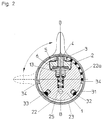
- Fig. 1 shows the gas fitting in longitudinal section.
- the base body 1 e.g. made of brass or stainless steel
- the compressed gas source e.g. compressed gas line.
- the shut-off element which preferably (as shown) consists of one Diaphragm valve exists.
- the outer end of pressure piece 4 of the diaphragm valve is flattened twice (end with a square). On this end with a square of Pressure piece 4, the gear 3 is movable (movement perpendicular to the rotary movement of the gear).
- the pressure piece 4 has an external thread, that moves in the internal thread of the retaining screw 2 when the gear 3 rotates becomes.
- a rotary movement of the gear 3 generates a lifting movement of the Pressure piece 4.
- the gear 3 does not follow the stroke movement of the Pressure piece 4.
- the teeth engage on the lower edge of the shut-off ring 22. Since the function open / close of the shut-off element by turning a quarter circle (Rotation through 90 °) of the shut-off ring 22 is to be reached, a toothing extends over a quarter of the circumference of the lower edge of the Shut-off ring 22 (see FIG. 3).
- the gear ratio of gear 3 and Teeth of the locking ring 22 is chosen accordingly.
- a translation e.g. B.
- the pressure control stage shown consists of a membrane pressure regulator with membrane rod 19, membrane 8, locking bolt 13 ', upper compression spring 18 and lower compression spring 18 '.
- the pressure control stage is made up of base body 1 and spring cover 9 enclosed.
- Spring cover 9 has an external thread at the upper end, on which the regulating screw 14 sits.
- the regulating screw 14 has one External hexagon.
- Handle part 10 has a hexagon socket in the lower area shaped recess.
- the hexagon socket of handle part 10 takes the hexagon socket from regulating screw 14.
- Adjusting screw 14 moves on the thread of spring cover 9, two Push pin 16 are moved up or down.
- the external hexagon of the regulating screw 14 moves in that of the hexagon socket of the handle part 10 formed channel.
- the lower edge of handle part 10 is slightly curved inwards.
- the edge of the handle part sits in a groove of the spring cover 9 (shown in Fig. 1).
- the pressure bolts 16 transmit the movement of the regulating screw 14 on the upper spring stop 17.
- the compressive force of the spring 18 on the diaphragm rod 19 with lower spring stop is adjusted.
- the membrane rod 19 sits down over the membrane screw 21, which is a gas channel contains, continues in the locking bolt 13 '.
- the locking bolt 13 has one square end (square).
- the square moves in the round hole of the gas channel in which a compression spring 18 'provides counter pressure.
- Pressure control unit leaves the gas at reduced pressure via a gas channel with side exit 1b on the base body 1.
- Another special feature is the Gas fitting in the area of the handle part 10, a manometer 38, which has a central Bore in the membrane rod 19 (membrane rod 19 is hollow) and one Gas channel in the membrane screw 21 with the gas channel on the reduced side Pressure (back pressure) is connected.
- the pressure gauge 38 is on the central gas inlet with the hollow membrane rod 19 via a Plug connection connected (fixation and securing with grub screw).
- the pressure gauge 38 with the pressure display 11 and pointer 11a is covered by a transparent, arched window 37 readable.
- the legibility of the print is from the front and possible from the side.
- the window 37 is attached to the manometer 38.
- the gas valve is on the clamping sleeve 24 (preferably right-hand thread and Left-hand thread) connected to the pressure line (gas source).
- the gas valve When installing in laboratory furniture, the gas valve is preferred in a laboratory furniture wall mounted so that the gas valve in the area of the (lower) cladding 23, that is below the shut-off ring 22 and above the gas outlet 1b, is installed in the laboratory furniture wall.
- the gas outlet is then behind the Laboratory furniture wall, free for the connection of a gas sampling line.
- the gas extraction line usually leads to a gas sampling valve (metering valve) that is also attached to the laboratory furniture wall and from the front like that Gas valve is operated. From the gas sampling valve leads a gas line (e.g. B. pipe or hose line) to the consumer.
- a gas line e.g. B. pipe or hose line
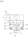
- Fig. 2 shows the gas valve of Fig. 1 in cross section along the line BB.
- the shut-off element in the base body 1, consisting of a diaphragm valve with the parts compression spring 25, locking pin 13, diaphragm 6, slide washer 5 and pressure piece 4 with gear 3, the shut-off ring 22 with the teeth 22a on the lower edge of the shut-off ring 22.
- the teeth 22a extends over a quarter of the circumference of shut-off ring 22 (extension of shut-off ring 22 in the area of toothing 22a).
- the position flag 30 is attached to the shut-off ring 22, preferably via a plug connection.
- the position flag 30 serves as a handle for actuating the shut-off element.
- the covering 23 is provided with two limiting ribs 34 at a distance of 180 °, which are attached in the region of the toothing 22a and form stops for the ends of the toothing 22a (see FIG. 3).
- the position flag 30 shown in broken lines shows the closed position ( To ”) after rotation of the flag 30 with locking ring 22 by 90 °.
- the On and The locking ring 22 is set in a noticeable manner with the aid of a locking device.
- the locking device holds the locking ring in the set position.
- the locking piece 33 is designed as a peg-shaped extension of the lower edge of the locking ring 22.
- the locking piece 33 contains a locking opening for the ball thrust piece 32.
- the ball thrust piece 32 with a compression spring is located in the receiving opening 31 in the base body 1.
- shut-off ring 22 By turning the shut-off ring 22 is over the engaging in the gear 3 Teeth 22a on the (lower) edge of the shut-off ring facing the gear 3 22 converted the rotary movement into a lifting movement.
- the relationship (Translation) the number of teeth of gear 3 and toothing 22a chosen so that the rotation of the locking ring 22 by 90 ° is a lifting movement of the pressure piece 4, which is transmitted to the locking bolt 13, for opening and closing the shut-off element is sufficient.
- a diaphragm valve, gas pressure and spring pressure of the spring act 25 in same direction, that is in the closing direction of the closing cone of Locking Bolt 13. This unusual alignment of gas pressure and spring pressure (opposite pressure directions are common) provides additional security at the shut-off element.
- Fig. 3 shows the lower part of the gas fitting.
- the interaction of shut-off ring 22 with teeth 22a and gear 3 is shown. You recognize them a quarter circle arc limited toothing 22a and extension on the Locking ring 22.
- the two limiting ribs 34 serve as a stop for the two End edges of the shut-off ring section with the toothing 22a.
- By the Interaction of the toothing 22a and gear 3 is a rotation around the Longitudinal axis of the gas valve in a rotation about an axis perpendicular to Longitudinal axis implemented.
- the holding screw 2 has recesses arranged at a 90 ° spacing on the upper side for mounting on (circles shown in Fig. 3 without numbering).
- Fig. 4 shows the gas fitting in plan view (from above; from the operator side).
- the pressure regulator is operated by means of the handle part 10.
- the handle part 10 is the manometer 38 with pressure display 11 (pressure scale and pressure pointer 11a) and a transparent, preferably curved plastic cover 37 (window) integrated, wherein handle part 10 and the pressure measuring and pressure display unit with pressure gauge 38 are mechanically separated.
- the window 37 is preferred in the central area flat. The flat area of the window bears the gas type adhesive label 12.
- Fig. 5 shows the gas valve in a side view.
- the cladding 23 contains an opening or a recess 39 as a viewing window for indicating the position (open / closed state) of the shut-off element.
- the viewing window 39 shows one of two position markings (90 ° apart) On "or
- the position flag 30 is attached to the shut-off ring 22.
- the position flag 30 is preferably attached to the shut-off ring 22 by clipping on.
- the position flag 30 advantageously has the color typical of the gas type.
- the gas fitting can be used universally (that is, for the different gases) an interchangeable position flag 30 and gas type sticker 12, the gas valve can be easily adapted to the gas type to be used.
Landscapes
- Engineering & Computer Science (AREA)
- Mechanical Engineering (AREA)
- General Engineering & Computer Science (AREA)
- Filling Or Discharging Of Gas Storage Vessels (AREA)
- Glass Compositions (AREA)
- Safety Valves (AREA)
- Mechanically-Actuated Valves (AREA)
- Measuring Volume Flow (AREA)
- Control Of Fluid Pressure (AREA)
- Indication Of The Valve Opening Or Closing Status (AREA)
Abstract
Description
- Variantenvielfalt der Labor-Gasentnahmestellen, bedingt durch verschiedene Einbausituationen in den Labormöbeln: Tischarmatur, Energiezeilen, Energiebrücken, Abzugsarmatur (lang und schmal) und Standsäulen-Armatur,
- unübersichtliches Erscheinungsbild durch verschiedene Bedienebenen und viele Ecken und Kanten,
- eine Vielzahl von Abdichtstellen und Verschraubungen zwischen den einzelnen Bauteilen,
- zu große Abmessungen,
- ein hoher Aufwand für die Lagerhaltung durch die Teilevielfalt,
- aufwendige Wartung,
- ungenügende Ergonomie und
- zu hohes Gewicht.
- 1
- Grundkörper
- 1a
- Gaseingang
- 1b
- Gasausgang
- 2
- Halteschraube
- 3
- Zahnrad
- 4
- Druckstück
- 5
- Gleitscheibe (Metall, PTFE-beschichtet)
- 6
- Membran
- 7
- Gleitring
- 8
- Membran mit Loch
- 9
- Federdeckel
- 10
- Bedienelement des Druckreglers (Griffteil)
- 11
- Druckanzeige
- 11a
- Druckzeiger
- 12
- Gasart-Klebeschild
- 13, 13'
- Schließbolzen
- 14
- Stellmutter (Regulierschraube)
- 15
- Dichtung
- 16
- Druckbolzen
- 17
- oberer Federanschlag
- 18, 18'
- Feder
- 19
- Membranstange (mit unterem Federanschlag)
- 20
- Membrandichtung
- 21
- Membranschraube
- 22
- Absperr-Ring
- 22a
- Verzahnung auf Absperr-Ringkante
- 23
- Verkleidung
- 24
- Spannmuffe
- 25
- Druckfeder
- 27
- Ventilsitzdichtung
- 29
- Ventilsitzschraube
- 30
- Stellungsfahne
- 31
- Aufnahmeöffnung für Druckfeder und Kugel der Einrastvorrichtung
- 32
- Kugel (Kugeldruckstück)
- 33
- Einraststück (Verlängerung von Absperr-Ring 22)
- 34
- Begrenzungsrippe in der Verkleidung
- 35
- Anschluß zur Druckgasleitung
- 36
- Befestigungsnippel
- 37
- Fenster der Druckanzeige
- 38
- Druckmeßinstrument (Manometer)
- 39
- Fenster oder Aussparung zur Stellungsanzeige
Claims (10)
- Gasarmatur mit Vordruckabsperrelement, Druckregler und Manometer (38) zur Druckanzeige, dadurch gekennzeichnet, daß Vordruckabsperrelement und Druckregler in einer Reihe zwischen Manometer (38) und Druckgasquelle und Manometer (38) mit Druckanzeige (11) innerhalb des Bedienelementes (10) für den Druckregler angeordnet sind.
- Gasarmatur nach Anspruch 1, dadurch gekennzeichnet, daß das Bedienelement (10) einen Hohlraum zur Aufnahme des Manometers (38) aufweist.
- Gasarmatur nach Anspruch 1 oder 2, dadurch gekennzeichnet, daß das Absperrelement über einen Absperring 22 betätigt wird.
- Gasarmatur nach Anspruch 3, dadurch gekennzeichnet, daß der Absperring (22) durch Drehen oder Schieben betätigt wird.
- Gasarmatur nach Anspruch 3, dadurch gekennzeichnet, daß der Absperring (22) durch Drehen betätigt wird und das Absperrelement mit dem Absperring (22) mittels einer Übersetzung verbunden ist.
- Gasarmatur nach Anspruch 5, dadurch gekennzeichnet, daß die Übersetzung durch eine Verzahnung (22a) an dem Absperring (22) und ein Zahnrad (3) des Absperrelementes gebildet wird.
- Gasarmatur nach einem der Ansprüche 1 bis 6, dadurch gekennzeichnet, daß das Absperrelement ein Ventil mit Druckfeder (25) und Schließbolzen (13) mit Schließkegel ist und der Gasdruck und die Druckfeder (25) in einer Richtung wirken und einen Druck auf den Schließkegel ausüben.
- Gasarmatur nach einem der Ansprüche 1 bis 7, dadurch gekennzeichnet, daß das Manometer (38) mit der Vordruckseite über ein Hohlteil (19), das ein Teil des Druckreglers ist, verbunden ist.
- Verwendung der Gasarmatur nach einem der Ansprüche 1 bis 8 im Laborbereich oder für Labormöbel.
- Verwendung nach Anspruch 9, dadurch gekennzeichnet, daß die Gasarmatur mit einem Gasdosierventil kombiniert wird.
Applications Claiming Priority (2)
| Application Number | Priority Date | Filing Date | Title |
|---|---|---|---|
| DE19822369 | 1998-05-19 | ||
| DE19822369A DE19822369B4 (de) | 1998-05-19 | 1998-05-19 | Gasarmatur |
Publications (3)
| Publication Number | Publication Date |
|---|---|
| EP0959292A2 true EP0959292A2 (de) | 1999-11-24 |
| EP0959292A3 EP0959292A3 (de) | 2000-08-30 |
| EP0959292B1 EP0959292B1 (de) | 2005-09-07 |
Family
ID=7868244
Family Applications (1)
| Application Number | Title | Priority Date | Filing Date |
|---|---|---|---|
| EP98118966A Expired - Lifetime EP0959292B1 (de) | 1998-05-19 | 1998-10-07 | Gasarmatur |
Country Status (6)
| Country | Link |
|---|---|
| US (1) | US6009900A (de) |
| EP (1) | EP0959292B1 (de) |
| AT (1) | ATE304146T1 (de) |
| DE (2) | DE19822369B4 (de) |
| DK (1) | DK0959292T3 (de) |
| ES (1) | ES2248869T3 (de) |
Cited By (1)
| Publication number | Priority date | Publication date | Assignee | Title |
|---|---|---|---|---|
| WO2012093232A1 (fr) | 2011-01-07 | 2012-07-12 | Hampiaux S.A.S. | Détendeur de gaz pour outillage a main. |
Families Citing this family (21)
| Publication number | Priority date | Publication date | Assignee | Title |
|---|---|---|---|---|
| US6647982B1 (en) * | 1998-06-29 | 2003-11-18 | Zaiser Lenoir E. | Gas flow device |
| US6311682B1 (en) | 1999-01-22 | 2001-11-06 | Npf Limited | Paintball guns |
| US6615814B1 (en) * | 1999-03-18 | 2003-09-09 | Npf Limited | Paintball guns |
| US6474325B2 (en) * | 1999-01-22 | 2002-11-05 | Npf Limited | Gas regulator |
| DE19913230C2 (de) * | 1999-03-23 | 2001-06-21 | Vti Ventil Technik Gmbh | Ventilarmatur für einen Druckbehälter |
| US20040194829A1 (en) * | 2002-09-19 | 2004-10-07 | Zaiser Lenoir E. | Differential pressure valve employing near-balanced pressure |
| EP1405673A1 (de) * | 2002-10-04 | 2004-04-07 | S+B International B.V. | Versorgungseinheit für Trägerplatte |
| US7617826B1 (en) | 2004-02-26 | 2009-11-17 | Ameriflo, Inc. | Conserver |
| US8146592B2 (en) | 2004-02-26 | 2012-04-03 | Ameriflo, Inc. | Method and apparatus for regulating fluid flow or conserving fluid flow |
| JP4619722B2 (ja) * | 2004-08-11 | 2011-01-26 | 日本エア・リキード株式会社 | 容器バルブ |
| US7448594B2 (en) | 2004-10-21 | 2008-11-11 | Ameriflo, Inc. | Fluid regulator |
| EP1821020B1 (de) | 2006-02-18 | 2009-07-15 | Minimax GmbH & Co KG | Rohrkupplung für Flüssiggasleitung mit Nut |
| US7650904B2 (en) * | 2007-07-11 | 2010-01-26 | Yung-Chao Huang | Pressure-regulating valve with an integrated pressure gauge |
| DK2083255T3 (da) * | 2008-01-26 | 2012-05-14 | Tescom Europ Gmbh & Co Kg | Gasudvindingsindretning |
| GB0922355D0 (en) * | 2009-12-21 | 2010-02-03 | Linde Ag | Pressure vessel |
| US8336578B2 (en) * | 2010-05-04 | 2012-12-25 | Su-Hua Tai | Quick release gas pressure regulator |
| ITPD20130258A1 (it) * | 2013-09-20 | 2015-03-21 | Huber S P A | Gruppo rubinetto |
| FR3042584A1 (fr) * | 2015-10-20 | 2017-04-21 | Air Liquide | Bloc rdi de distribution de gaz avec dispositif indicateur agence au centre du volant de manœuvre |
| US20180128395A1 (en) * | 2016-11-10 | 2018-05-10 | Globe Fire Sprinkler Corporation | Ball valve with color-coded indicator of normal operating position |
| US12516738B2 (en) | 2021-08-04 | 2026-01-06 | Lincoln Global, Inc. | Valve with integrated pressure regulator |
| JP2024169312A (ja) * | 2023-05-24 | 2024-12-05 | リンカーン グローバル,インコーポレイテッド | 一体型圧力調整器を備えた弁 |
Family Cites Families (12)
| Publication number | Priority date | Publication date | Assignee | Title |
|---|---|---|---|---|
| US3511266A (en) * | 1967-03-13 | 1970-05-12 | Firewel Co Inc | Shut off and pressure regulating valve |
| DE1648669C3 (de) * | 1967-04-26 | 1974-06-12 | Gesellschaft Fuer Hydraulik-Zubehoer Mbh, 6603 Sulzbach | Manometer-Wahlventil |
| CH535603A (de) * | 1972-03-14 | 1973-04-15 | Nussbaum & Co Ag R | Installationszelle für Fluida |
| US4187881A (en) * | 1978-06-23 | 1980-02-12 | Acf Industries, Incorporated | Cone valve assembly |
| US4655246A (en) * | 1983-09-30 | 1987-04-07 | Essex Industries, Inc. | Regulated gas flow control valve |
| LU86802A1 (fr) * | 1987-03-09 | 1987-08-12 | Ceodeux Sa | Centrale de commande pour gaz sous pression |
| DE4001170A1 (de) * | 1990-01-17 | 1991-07-18 | Roland Man Druckmasch | Einschraubventilkoerper-bausatz, insbesondere fuer ein drosselventil |
| DE4223233C1 (de) * | 1992-07-15 | 1993-09-30 | Messer Griesheim Gmbh | Entnahmestelleneinrichtung für Gase |
| FR2706051B1 (fr) * | 1993-06-03 | 1995-07-28 | Taema | Ensemble de commande de distribution de gaz et bouteille de gaz équipée d'un tel ensemble. |
| NL9301875A (nl) * | 1993-11-01 | 1995-06-01 | Applied Power Inc | Hydraulische stuurklep. |
| FR2735209B1 (fr) * | 1995-06-08 | 1997-07-25 | Air Liquide | Ensemble robinet/detendeur pour bouteille de gaz et bouteille de gaz equipee d'un tel ensemble |
| FR2761454B1 (fr) * | 1997-04-01 | 2000-02-25 | Gce Charledave | Robinet a manometre pour bouteille de gaz comprime |
-
1998
- 1998-05-19 DE DE19822369A patent/DE19822369B4/de not_active Expired - Fee Related
- 1998-10-07 DK DK98118966T patent/DK0959292T3/da active
- 1998-10-07 DE DE59813044T patent/DE59813044D1/de not_active Expired - Lifetime
- 1998-10-07 AT AT98118966T patent/ATE304146T1/de active
- 1998-10-07 EP EP98118966A patent/EP0959292B1/de not_active Expired - Lifetime
- 1998-10-07 ES ES98118966T patent/ES2248869T3/es not_active Expired - Lifetime
- 1998-12-14 US US09/211,169 patent/US6009900A/en not_active Expired - Lifetime
Cited By (2)
| Publication number | Priority date | Publication date | Assignee | Title |
|---|---|---|---|---|
| WO2012093232A1 (fr) | 2011-01-07 | 2012-07-12 | Hampiaux S.A.S. | Détendeur de gaz pour outillage a main. |
| FR2970349A1 (fr) * | 2011-01-07 | 2012-07-13 | Hampiaux S A S | Detendeur de gaz pour outillage a main |
Also Published As
| Publication number | Publication date |
|---|---|
| US6009900A (en) | 2000-01-04 |
| ES2248869T3 (es) | 2006-03-16 |
| DK0959292T3 (da) | 2005-12-12 |
| EP0959292B1 (de) | 2005-09-07 |
| DE19822369A1 (de) | 1999-11-25 |
| ATE304146T1 (de) | 2005-09-15 |
| DE59813044D1 (de) | 2005-10-13 |
| DE19822369B4 (de) | 2006-01-05 |
| EP0959292A3 (de) | 2000-08-30 |
Similar Documents
| Publication | Publication Date | Title |
|---|---|---|
| EP0959292B1 (de) | Gasarmatur | |
| DE69116029T2 (de) | Mit Ventilen kombiniertes modulares Steuerpult | |
| EP0228068B1 (de) | Eine Druckminderungsanzeige liefernde Ventilkappe für Luftreifen | |
| EP0579889A1 (de) | Mischer mit Vorsatz | |
| EP0959293A2 (de) | Gasentnahmesystem für Druckgasbehälter | |
| DE4401787A1 (de) | Strömungsmesserbaugruppe | |
| DE3100769A1 (de) | "gasreiniger" | |
| DE19744048A1 (de) | Gasentnahmesystem | |
| EP0139943B1 (de) | Drosselvorrichtung | |
| DE3928733A1 (de) | Manometer mit mehreren bourdon-roehrenspulen | |
| DE2416359C3 (de) | Ventil für aggressive Medien | |
| DE8700972U1 (de) | Bourdon-Meßinstrument | |
| WO2008043360A1 (de) | Durchflusseinstellventil | |
| DE4102134A1 (de) | Beruehrungslos gesteuerte sanitaerarmatur | |
| DE102018125499A1 (de) | Sichtfenster für RLT-Anlagen und Klimakammern | |
| DE3545393C2 (de) | ||
| DE19822364A1 (de) | Bedienelement mit Druckanzeige | |
| DE3515752A1 (de) | Strangregulierventil | |
| DE19822367B4 (de) | Verstelleinrichtung für Absperrelelmente von Druckgasquellen | |
| WO2020078509A1 (de) | Sichtfenster für rlt-anlagen und klimakammern | |
| DE3825575C2 (de) | ||
| DE4007279C2 (de) | Anschlußvorrichtung für Einstutzen-Gaszähler | |
| DE19852471A1 (de) | Gasentnahmesystem mit austauschbarem Anschluß | |
| WO1995029821A1 (de) | Verbindungsglied zum verbinden der jeweiligen ventile der beiden luftreifen eines zwillingsluftreifens und ausgleichskappe | |
| EP1014066B1 (de) | Differenzdruckmessgerät |
Legal Events
| Date | Code | Title | Description |
|---|---|---|---|
| PUAI | Public reference made under article 153(3) epc to a published international application that has entered the european phase |
Free format text: ORIGINAL CODE: 0009012 |
|
| AK | Designated contracting states |
Kind code of ref document: A2 Designated state(s): AT BE CH DE DK ES FR GB IT LI LU NL SE |
|
| AX | Request for extension of the european patent |
Free format text: AL;LT;LV;MK;RO;SI |
|
| PUAL | Search report despatched |
Free format text: ORIGINAL CODE: 0009013 |
|
| AK | Designated contracting states |
Kind code of ref document: A3 Designated state(s): AT BE CH CY DE DK ES FI FR GB GR IE IT LI LU MC NL PT SE |
|
| AX | Request for extension of the european patent |
Free format text: AL;LT;LV;MK;RO;SI |
|
| 17P | Request for examination filed |
Effective date: 20010228 |
|
| AKX | Designation fees paid |
Free format text: AT BE CH DE DK ES FR GB IT LI LU NL SE |
|
| GRAP | Despatch of communication of intention to grant a patent |
Free format text: ORIGINAL CODE: EPIDOSNIGR1 |
|
| GRAS | Grant fee paid |
Free format text: ORIGINAL CODE: EPIDOSNIGR3 |
|
| GRAA | (expected) grant |
Free format text: ORIGINAL CODE: 0009210 |
|
| AK | Designated contracting states |
Kind code of ref document: B1 Designated state(s): AT BE CH DE DK ES FR GB IT LI LU NL SE |
|
| REG | Reference to a national code |
Ref country code: GB Ref legal event code: FG4D Free format text: NOT ENGLISH |
|
| REG | Reference to a national code |
Ref country code: CH Ref legal event code: EP |
|
| REF | Corresponds to: |
Ref document number: 59813044 Country of ref document: DE Date of ref document: 20051013 Kind code of ref document: P |
|
| REG | Reference to a national code |
Ref country code: DK Ref legal event code: T3 |
|
| REG | Reference to a national code |
Ref country code: SE Ref legal event code: TRGR |
|
| REG | Reference to a national code |
Ref country code: CH Ref legal event code: NV Representative=s name: BREITER + PARTNER AG PATENT - UND MARKENBUERO |
|
| RAP2 | Party data changed (patent owner data changed or rights of a patent transferred) |
Owner name: MESSER CUTTING & WELDING GMBH |
|
| REG | Reference to a national code |
Ref country code: CH Ref legal event code: PUE Owner name: MESSER CUTTING & WELDING GMBH Free format text: MESSER GRIESHEIM SCHWEISSTECHNIK GMBH + CO.#OTTO-HAHN-STRASSE 2-4#64823 GROSS-UMSTADT (DE) -TRANSFER TO- MESSER CUTTING & WELDING GMBH#OTTO-HAHN-STRASSE 2-4#64823 GROSS-UMSTADT (DE) |
|
| GBT | Gb: translation of ep patent filed (gb section 77(6)(a)/1977) |
Effective date: 20060125 |
|
| REG | Reference to a national code |
Ref country code: ES Ref legal event code: FG2A Ref document number: 2248869 Country of ref document: ES Kind code of ref document: T3 |
|
| NLT2 | Nl: modifications (of names), taken from the european patent patent bulletin |
Owner name: MESSER CUTTING & WELDING GMBH Effective date: 20060125 |
|
| ET | Fr: translation filed | ||
| REG | Reference to a national code |
Ref country code: FR Ref legal event code: CD |
|
| PLBE | No opposition filed within time limit |
Free format text: ORIGINAL CODE: 0009261 |
|
| STAA | Information on the status of an ep patent application or granted ep patent |
Free format text: STATUS: NO OPPOSITION FILED WITHIN TIME LIMIT |
|
| 26N | No opposition filed |
Effective date: 20060608 |
|
| REG | Reference to a national code |
Ref country code: CH Ref legal event code: PFA Owner name: MESSER CUTTING & WELDING GMBH Free format text: MESSER CUTTING & WELDING GMBH#OTTO-HAHN-STRASSE 2-4#64823 GROSS-UMSTADT (DE) -TRANSFER TO- MESSER CUTTING & WELDING GMBH#OTTO-HAHN-STRASSE 2-4#64823 GROSS-UMSTADT (DE) |
|
| REG | Reference to a national code |
Ref country code: FR Ref legal event code: PLFP Year of fee payment: 18 |
|
| PGFP | Annual fee paid to national office [announced via postgrant information from national office to epo] |
Ref country code: DK Payment date: 20151021 Year of fee payment: 18 |
|
| PGFP | Annual fee paid to national office [announced via postgrant information from national office to epo] |
Ref country code: CH Payment date: 20151021 Year of fee payment: 18 Ref country code: IT Payment date: 20151028 Year of fee payment: 18 |
|
| PGFP | Annual fee paid to national office [announced via postgrant information from national office to epo] |
Ref country code: BE Payment date: 20151019 Year of fee payment: 18 Ref country code: ES Payment date: 20151028 Year of fee payment: 18 Ref country code: FR Payment date: 20151023 Year of fee payment: 18 Ref country code: SE Payment date: 20151021 Year of fee payment: 18 Ref country code: AT Payment date: 20151022 Year of fee payment: 18 Ref country code: NL Payment date: 20151021 Year of fee payment: 18 |
|
| PGFP | Annual fee paid to national office [announced via postgrant information from national office to epo] |
Ref country code: LU Payment date: 20161026 Year of fee payment: 19 |
|
| PGFP | Annual fee paid to national office [announced via postgrant information from national office to epo] |
Ref country code: GB Payment date: 20161020 Year of fee payment: 19 Ref country code: DE Payment date: 20161020 Year of fee payment: 19 |
|
| PG25 | Lapsed in a contracting state [announced via postgrant information from national office to epo] |
Ref country code: BE Free format text: LAPSE BECAUSE OF NON-PAYMENT OF DUE FEES Effective date: 20161031 |
|
| REG | Reference to a national code |
Ref country code: DK Ref legal event code: EBP Effective date: 20161031 |
|
| REG | Reference to a national code |
Ref country code: CH Ref legal event code: PL |
|
| REG | Reference to a national code |
Ref country code: NL Ref legal event code: MM Effective date: 20161101 |
|
| REG | Reference to a national code |
Ref country code: AT Ref legal event code: MM01 Ref document number: 304146 Country of ref document: AT Kind code of ref document: T Effective date: 20161007 |
|
| REG | Reference to a national code |
Ref country code: FR Ref legal event code: ST Effective date: 20170630 |
|
| PG25 | Lapsed in a contracting state [announced via postgrant information from national office to epo] |
Ref country code: LI Free format text: LAPSE BECAUSE OF NON-PAYMENT OF DUE FEES Effective date: 20161031 Ref country code: FR Free format text: LAPSE BECAUSE OF NON-PAYMENT OF DUE FEES Effective date: 20161102 Ref country code: CH Free format text: LAPSE BECAUSE OF NON-PAYMENT OF DUE FEES Effective date: 20161031 |
|
| PG25 | Lapsed in a contracting state [announced via postgrant information from national office to epo] |
Ref country code: AT Free format text: LAPSE BECAUSE OF NON-PAYMENT OF DUE FEES Effective date: 20161007 Ref country code: SE Free format text: LAPSE BECAUSE OF NON-PAYMENT OF DUE FEES Effective date: 20161008 Ref country code: NL Free format text: LAPSE BECAUSE OF NON-PAYMENT OF DUE FEES Effective date: 20161101 |
|
| PG25 | Lapsed in a contracting state [announced via postgrant information from national office to epo] |
Ref country code: IT Free format text: LAPSE BECAUSE OF NON-PAYMENT OF DUE FEES Effective date: 20161007 |
|
| PG25 | Lapsed in a contracting state [announced via postgrant information from national office to epo] |
Ref country code: DK Free format text: LAPSE BECAUSE OF NON-PAYMENT OF DUE FEES Effective date: 20161031 |
|
| REG | Reference to a national code |
Ref country code: BE Ref legal event code: MM Effective date: 20161031 |
|
| REG | Reference to a national code |
Ref country code: DE Ref legal event code: R119 Ref document number: 59813044 Country of ref document: DE |
|
| PG25 | Lapsed in a contracting state [announced via postgrant information from national office to epo] |
Ref country code: ES Free format text: LAPSE BECAUSE OF FAILURE TO SUBMIT A TRANSLATION OF THE DESCRIPTION OR TO PAY THE FEE WITHIN THE PRESCRIBED TIME-LIMIT Effective date: 20050907 |
|
| GBPC | Gb: european patent ceased through non-payment of renewal fee |
Effective date: 20171007 |
|
| PG25 | Lapsed in a contracting state [announced via postgrant information from national office to epo] |
Ref country code: DE Free format text: LAPSE BECAUSE OF NON-PAYMENT OF DUE FEES Effective date: 20180501 Ref country code: GB Free format text: LAPSE BECAUSE OF NON-PAYMENT OF DUE FEES Effective date: 20171007 Ref country code: LU Free format text: LAPSE BECAUSE OF NON-PAYMENT OF DUE FEES Effective date: 20171007 |
|
| REG | Reference to a national code |
Ref country code: ES Ref legal event code: FD2A Effective date: 20181116 |
|
| RIC2 | Information provided on ipc code assigned after grant |
Ipc: F17C 13/04 20060101AFI19990916BHEP Ipc: B01L 9/02 20060101ALI19990916BHEP |
|
| PG25 | Lapsed in a contracting state [announced via postgrant information from national office to epo] |
Ref country code: ES Free format text: LAPSE BECAUSE OF FAILURE TO SUBMIT A TRANSLATION OF THE DESCRIPTION OR TO PAY THE FEE WITHIN THE PRESCRIBED TIME-LIMIT Effective date: 20161008 |