EP0959314B1 - Indirekt befeuerte Gasturbine integriert in einer Luftzerlegungsanlage - Google Patents
Indirekt befeuerte Gasturbine integriert in einer Luftzerlegungsanlage Download PDFInfo
- Publication number
- EP0959314B1 EP0959314B1 EP99303843A EP99303843A EP0959314B1 EP 0959314 B1 EP0959314 B1 EP 0959314B1 EP 99303843 A EP99303843 A EP 99303843A EP 99303843 A EP99303843 A EP 99303843A EP 0959314 B1 EP0959314 B1 EP 0959314B1
- Authority
- EP
- European Patent Office
- Prior art keywords
- stream
- air
- pressurized air
- nitrogen
- pressurized
- Prior art date
- Legal status (The legal status is an assumption and is not a legal conclusion. Google has not performed a legal analysis and makes no representation as to the accuracy of the status listed.)
- Expired - Lifetime
Links
Images

Classifications
-
- F—MECHANICAL ENGINEERING; LIGHTING; HEATING; WEAPONS; BLASTING
- F02—COMBUSTION ENGINES; HOT-GAS OR COMBUSTION-PRODUCT ENGINE PLANTS
- F02C—GAS-TURBINE PLANTS; AIR INTAKES FOR JET-PROPULSION PLANTS; CONTROLLING FUEL SUPPLY IN AIR-BREATHING JET-PROPULSION PLANTS
- F02C1/00—Gas-turbine plants characterised by the use of hot gases or unheated pressurised gases, as the working fluid
- F02C1/04—Gas-turbine plants characterised by the use of hot gases or unheated pressurised gases, as the working fluid the working fluid being heated indirectly
-
- F—MECHANICAL ENGINEERING; LIGHTING; HEATING; WEAPONS; BLASTING
- F25—REFRIGERATION OR COOLING; COMBINED HEATING AND REFRIGERATION SYSTEMS; HEAT PUMP SYSTEMS; MANUFACTURE OR STORAGE OF ICE; LIQUEFACTION SOLIDIFICATION OF GASES
- F25J—LIQUEFACTION, SOLIDIFICATION OR SEPARATION OF GASES OR GASEOUS OR LIQUEFIED GASEOUS MIXTURES BY PRESSURE AND COLD TREATMENT OR BY BRINGING THEM INTO THE SUPERCRITICAL STATE
- F25J3/00—Processes or apparatus for separating the constituents of gaseous or liquefied gaseous mixtures involving the use of liquefaction or solidification
- F25J3/02—Processes or apparatus for separating the constituents of gaseous or liquefied gaseous mixtures involving the use of liquefaction or solidification by rectification, i.e. by continuous interchange of heat and material between a vapour stream and a liquid stream
- F25J3/04—Processes or apparatus for separating the constituents of gaseous or liquefied gaseous mixtures involving the use of liquefaction or solidification by rectification, i.e. by continuous interchange of heat and material between a vapour stream and a liquid stream for air
- F25J3/04006—Providing pressurised feed air or process streams within or from the air fractionation unit
- F25J3/04012—Providing pressurised feed air or process streams within or from the air fractionation unit by compression of warm gaseous streams; details of intake or interstage cooling
- F25J3/04018—Providing pressurised feed air or process streams within or from the air fractionation unit by compression of warm gaseous streams; details of intake or interstage cooling of main feed air
-
- F—MECHANICAL ENGINEERING; LIGHTING; HEATING; WEAPONS; BLASTING
- F25—REFRIGERATION OR COOLING; COMBINED HEATING AND REFRIGERATION SYSTEMS; HEAT PUMP SYSTEMS; MANUFACTURE OR STORAGE OF ICE; LIQUEFACTION SOLIDIFICATION OF GASES
- F25J—LIQUEFACTION, SOLIDIFICATION OR SEPARATION OF GASES OR GASEOUS OR LIQUEFIED GASEOUS MIXTURES BY PRESSURE AND COLD TREATMENT OR BY BRINGING THEM INTO THE SUPERCRITICAL STATE
- F25J3/00—Processes or apparatus for separating the constituents of gaseous or liquefied gaseous mixtures involving the use of liquefaction or solidification
- F25J3/02—Processes or apparatus for separating the constituents of gaseous or liquefied gaseous mixtures involving the use of liquefaction or solidification by rectification, i.e. by continuous interchange of heat and material between a vapour stream and a liquid stream
- F25J3/04—Processes or apparatus for separating the constituents of gaseous or liquefied gaseous mixtures involving the use of liquefaction or solidification by rectification, i.e. by continuous interchange of heat and material between a vapour stream and a liquid stream for air
- F25J3/04006—Providing pressurised feed air or process streams within or from the air fractionation unit
- F25J3/04109—Arrangements of compressors and /or their drivers
-
- F—MECHANICAL ENGINEERING; LIGHTING; HEATING; WEAPONS; BLASTING
- F25—REFRIGERATION OR COOLING; COMBINED HEATING AND REFRIGERATION SYSTEMS; HEAT PUMP SYSTEMS; MANUFACTURE OR STORAGE OF ICE; LIQUEFACTION SOLIDIFICATION OF GASES
- F25J—LIQUEFACTION, SOLIDIFICATION OR SEPARATION OF GASES OR GASEOUS OR LIQUEFIED GASEOUS MIXTURES BY PRESSURE AND COLD TREATMENT OR BY BRINGING THEM INTO THE SUPERCRITICAL STATE
- F25J3/00—Processes or apparatus for separating the constituents of gaseous or liquefied gaseous mixtures involving the use of liquefaction or solidification
- F25J3/02—Processes or apparatus for separating the constituents of gaseous or liquefied gaseous mixtures involving the use of liquefaction or solidification by rectification, i.e. by continuous interchange of heat and material between a vapour stream and a liquid stream
- F25J3/04—Processes or apparatus for separating the constituents of gaseous or liquefied gaseous mixtures involving the use of liquefaction or solidification by rectification, i.e. by continuous interchange of heat and material between a vapour stream and a liquid stream for air
- F25J3/04006—Providing pressurised feed air or process streams within or from the air fractionation unit
- F25J3/04109—Arrangements of compressors and /or their drivers
- F25J3/04115—Arrangements of compressors and /or their drivers characterised by the type of prime driver, e.g. hot gas expander
-
- F—MECHANICAL ENGINEERING; LIGHTING; HEATING; WEAPONS; BLASTING
- F25—REFRIGERATION OR COOLING; COMBINED HEATING AND REFRIGERATION SYSTEMS; HEAT PUMP SYSTEMS; MANUFACTURE OR STORAGE OF ICE; LIQUEFACTION SOLIDIFICATION OF GASES
- F25J—LIQUEFACTION, SOLIDIFICATION OR SEPARATION OF GASES OR GASEOUS OR LIQUEFIED GASEOUS MIXTURES BY PRESSURE AND COLD TREATMENT OR BY BRINGING THEM INTO THE SUPERCRITICAL STATE
- F25J3/00—Processes or apparatus for separating the constituents of gaseous or liquefied gaseous mixtures involving the use of liquefaction or solidification
- F25J3/02—Processes or apparatus for separating the constituents of gaseous or liquefied gaseous mixtures involving the use of liquefaction or solidification by rectification, i.e. by continuous interchange of heat and material between a vapour stream and a liquid stream
- F25J3/04—Processes or apparatus for separating the constituents of gaseous or liquefied gaseous mixtures involving the use of liquefaction or solidification by rectification, i.e. by continuous interchange of heat and material between a vapour stream and a liquid stream for air
- F25J3/04006—Providing pressurised feed air or process streams within or from the air fractionation unit
- F25J3/04109—Arrangements of compressors and /or their drivers
- F25J3/04139—Combination of different types of drivers mechanically coupled to the same compressor, possibly split on multiple compressor casings
-
- F—MECHANICAL ENGINEERING; LIGHTING; HEATING; WEAPONS; BLASTING
- F25—REFRIGERATION OR COOLING; COMBINED HEATING AND REFRIGERATION SYSTEMS; HEAT PUMP SYSTEMS; MANUFACTURE OR STORAGE OF ICE; LIQUEFACTION SOLIDIFICATION OF GASES
- F25J—LIQUEFACTION, SOLIDIFICATION OR SEPARATION OF GASES OR GASEOUS OR LIQUEFIED GASEOUS MIXTURES BY PRESSURE AND COLD TREATMENT OR BY BRINGING THEM INTO THE SUPERCRITICAL STATE
- F25J3/00—Processes or apparatus for separating the constituents of gaseous or liquefied gaseous mixtures involving the use of liquefaction or solidification
- F25J3/02—Processes or apparatus for separating the constituents of gaseous or liquefied gaseous mixtures involving the use of liquefaction or solidification by rectification, i.e. by continuous interchange of heat and material between a vapour stream and a liquid stream
- F25J3/04—Processes or apparatus for separating the constituents of gaseous or liquefied gaseous mixtures involving the use of liquefaction or solidification by rectification, i.e. by continuous interchange of heat and material between a vapour stream and a liquid stream for air
- F25J3/04521—Coupling of the air fractionation unit to an air gas-consuming unit, so-called integrated processes
- F25J3/04527—Integration with an oxygen consuming unit, e.g. glass facility, waste incineration or oxygen based processes in general
- F25J3/04539—Integration with an oxygen consuming unit, e.g. glass facility, waste incineration or oxygen based processes in general for the H2/CO synthesis by partial oxidation or oxygen consuming reforming processes of fuels
-
- F—MECHANICAL ENGINEERING; LIGHTING; HEATING; WEAPONS; BLASTING
- F25—REFRIGERATION OR COOLING; COMBINED HEATING AND REFRIGERATION SYSTEMS; HEAT PUMP SYSTEMS; MANUFACTURE OR STORAGE OF ICE; LIQUEFACTION SOLIDIFICATION OF GASES
- F25J—LIQUEFACTION, SOLIDIFICATION OR SEPARATION OF GASES OR GASEOUS OR LIQUEFIED GASEOUS MIXTURES BY PRESSURE AND COLD TREATMENT OR BY BRINGING THEM INTO THE SUPERCRITICAL STATE
- F25J3/00—Processes or apparatus for separating the constituents of gaseous or liquefied gaseous mixtures involving the use of liquefaction or solidification
- F25J3/02—Processes or apparatus for separating the constituents of gaseous or liquefied gaseous mixtures involving the use of liquefaction or solidification by rectification, i.e. by continuous interchange of heat and material between a vapour stream and a liquid stream
- F25J3/04—Processes or apparatus for separating the constituents of gaseous or liquefied gaseous mixtures involving the use of liquefaction or solidification by rectification, i.e. by continuous interchange of heat and material between a vapour stream and a liquid stream for air
- F25J3/04521—Coupling of the air fractionation unit to an air gas-consuming unit, so-called integrated processes
- F25J3/04563—Integration with a nitrogen consuming unit, e.g. for purging, inerting, cooling or heating
- F25J3/04575—Integration with a nitrogen consuming unit, e.g. for purging, inerting, cooling or heating for a gas expansion plant, e.g. dilution of the combustion gas in a gas turbine
- F25J3/04581—Hot gas expansion of indirect heated nitrogen
-
- F—MECHANICAL ENGINEERING; LIGHTING; HEATING; WEAPONS; BLASTING
- F25—REFRIGERATION OR COOLING; COMBINED HEATING AND REFRIGERATION SYSTEMS; HEAT PUMP SYSTEMS; MANUFACTURE OR STORAGE OF ICE; LIQUEFACTION SOLIDIFICATION OF GASES
- F25J—LIQUEFACTION, SOLIDIFICATION OR SEPARATION OF GASES OR GASEOUS OR LIQUEFIED GASEOUS MIXTURES BY PRESSURE AND COLD TREATMENT OR BY BRINGING THEM INTO THE SUPERCRITICAL STATE
- F25J3/00—Processes or apparatus for separating the constituents of gaseous or liquefied gaseous mixtures involving the use of liquefaction or solidification
- F25J3/02—Processes or apparatus for separating the constituents of gaseous or liquefied gaseous mixtures involving the use of liquefaction or solidification by rectification, i.e. by continuous interchange of heat and material between a vapour stream and a liquid stream
- F25J3/04—Processes or apparatus for separating the constituents of gaseous or liquefied gaseous mixtures involving the use of liquefaction or solidification by rectification, i.e. by continuous interchange of heat and material between a vapour stream and a liquid stream for air
- F25J3/04521—Coupling of the air fractionation unit to an air gas-consuming unit, so-called integrated processes
- F25J3/04593—The air gas consuming unit is also fed by an air stream
-
- F—MECHANICAL ENGINEERING; LIGHTING; HEATING; WEAPONS; BLASTING
- F25—REFRIGERATION OR COOLING; COMBINED HEATING AND REFRIGERATION SYSTEMS; HEAT PUMP SYSTEMS; MANUFACTURE OR STORAGE OF ICE; LIQUEFACTION SOLIDIFICATION OF GASES
- F25J—LIQUEFACTION, SOLIDIFICATION OR SEPARATION OF GASES OR GASEOUS OR LIQUEFIED GASEOUS MIXTURES BY PRESSURE AND COLD TREATMENT OR BY BRINGING THEM INTO THE SUPERCRITICAL STATE
- F25J3/00—Processes or apparatus for separating the constituents of gaseous or liquefied gaseous mixtures involving the use of liquefaction or solidification
- F25J3/02—Processes or apparatus for separating the constituents of gaseous or liquefied gaseous mixtures involving the use of liquefaction or solidification by rectification, i.e. by continuous interchange of heat and material between a vapour stream and a liquid stream
- F25J3/04—Processes or apparatus for separating the constituents of gaseous or liquefied gaseous mixtures involving the use of liquefaction or solidification by rectification, i.e. by continuous interchange of heat and material between a vapour stream and a liquid stream for air
- F25J3/04521—Coupling of the air fractionation unit to an air gas-consuming unit, so-called integrated processes
- F25J3/04593—The air gas consuming unit is also fed by an air stream
- F25J3/046—Completely integrated air feed compression, i.e. common MAC
-
- F—MECHANICAL ENGINEERING; LIGHTING; HEATING; WEAPONS; BLASTING
- F25—REFRIGERATION OR COOLING; COMBINED HEATING AND REFRIGERATION SYSTEMS; HEAT PUMP SYSTEMS; MANUFACTURE OR STORAGE OF ICE; LIQUEFACTION SOLIDIFICATION OF GASES
- F25J—LIQUEFACTION, SOLIDIFICATION OR SEPARATION OF GASES OR GASEOUS OR LIQUEFIED GASEOUS MIXTURES BY PRESSURE AND COLD TREATMENT OR BY BRINGING THEM INTO THE SUPERCRITICAL STATE
- F25J3/00—Processes or apparatus for separating the constituents of gaseous or liquefied gaseous mixtures involving the use of liquefaction or solidification
- F25J3/02—Processes or apparatus for separating the constituents of gaseous or liquefied gaseous mixtures involving the use of liquefaction or solidification by rectification, i.e. by continuous interchange of heat and material between a vapour stream and a liquid stream
- F25J3/04—Processes or apparatus for separating the constituents of gaseous or liquefied gaseous mixtures involving the use of liquefaction or solidification by rectification, i.e. by continuous interchange of heat and material between a vapour stream and a liquid stream for air
- F25J3/04521—Coupling of the air fractionation unit to an air gas-consuming unit, so-called integrated processes
- F25J3/04612—Heat exchange integration with process streams, e.g. from the air gas consuming unit
-
- F—MECHANICAL ENGINEERING; LIGHTING; HEATING; WEAPONS; BLASTING
- F25—REFRIGERATION OR COOLING; COMBINED HEATING AND REFRIGERATION SYSTEMS; HEAT PUMP SYSTEMS; MANUFACTURE OR STORAGE OF ICE; LIQUEFACTION SOLIDIFICATION OF GASES
- F25J—LIQUEFACTION, SOLIDIFICATION OR SEPARATION OF GASES OR GASEOUS OR LIQUEFIED GASEOUS MIXTURES BY PRESSURE AND COLD TREATMENT OR BY BRINGING THEM INTO THE SUPERCRITICAL STATE
- F25J3/00—Processes or apparatus for separating the constituents of gaseous or liquefied gaseous mixtures involving the use of liquefaction or solidification
- F25J3/02—Processes or apparatus for separating the constituents of gaseous or liquefied gaseous mixtures involving the use of liquefaction or solidification by rectification, i.e. by continuous interchange of heat and material between a vapour stream and a liquid stream
- F25J3/04—Processes or apparatus for separating the constituents of gaseous or liquefied gaseous mixtures involving the use of liquefaction or solidification by rectification, i.e. by continuous interchange of heat and material between a vapour stream and a liquid stream for air
- F25J3/04521—Coupling of the air fractionation unit to an air gas-consuming unit, so-called integrated processes
- F25J3/04612—Heat exchange integration with process streams, e.g. from the air gas consuming unit
- F25J3/04618—Heat exchange integration with process streams, e.g. from the air gas consuming unit for cooling an air stream fed to the air fractionation unit
-
- F—MECHANICAL ENGINEERING; LIGHTING; HEATING; WEAPONS; BLASTING
- F25—REFRIGERATION OR COOLING; COMBINED HEATING AND REFRIGERATION SYSTEMS; HEAT PUMP SYSTEMS; MANUFACTURE OR STORAGE OF ICE; LIQUEFACTION SOLIDIFICATION OF GASES
- F25J—LIQUEFACTION, SOLIDIFICATION OR SEPARATION OF GASES OR GASEOUS OR LIQUEFIED GASEOUS MIXTURES BY PRESSURE AND COLD TREATMENT OR BY BRINGING THEM INTO THE SUPERCRITICAL STATE
- F25J2215/00—Processes characterised by the type or other details of the product stream
- F25J2215/02—Mixing or blending of fluids to yield a certain product
-
- F—MECHANICAL ENGINEERING; LIGHTING; HEATING; WEAPONS; BLASTING
- F25—REFRIGERATION OR COOLING; COMBINED HEATING AND REFRIGERATION SYSTEMS; HEAT PUMP SYSTEMS; MANUFACTURE OR STORAGE OF ICE; LIQUEFACTION SOLIDIFICATION OF GASES
- F25J—LIQUEFACTION, SOLIDIFICATION OR SEPARATION OF GASES OR GASEOUS OR LIQUEFIED GASEOUS MIXTURES BY PRESSURE AND COLD TREATMENT OR BY BRINGING THEM INTO THE SUPERCRITICAL STATE
- F25J2230/00—Processes or apparatus involving steps for increasing the pressure of gaseous process streams
- F25J2230/06—Adiabatic compressor, i.e. without interstage cooling
-
- F—MECHANICAL ENGINEERING; LIGHTING; HEATING; WEAPONS; BLASTING
- F25—REFRIGERATION OR COOLING; COMBINED HEATING AND REFRIGERATION SYSTEMS; HEAT PUMP SYSTEMS; MANUFACTURE OR STORAGE OF ICE; LIQUEFACTION SOLIDIFICATION OF GASES
- F25J—LIQUEFACTION, SOLIDIFICATION OR SEPARATION OF GASES OR GASEOUS OR LIQUEFIED GASEOUS MIXTURES BY PRESSURE AND COLD TREATMENT OR BY BRINGING THEM INTO THE SUPERCRITICAL STATE
- F25J2230/00—Processes or apparatus involving steps for increasing the pressure of gaseous process streams
- F25J2230/40—Processes or apparatus involving steps for increasing the pressure of gaseous process streams the fluid being air
-
- F—MECHANICAL ENGINEERING; LIGHTING; HEATING; WEAPONS; BLASTING
- F25—REFRIGERATION OR COOLING; COMBINED HEATING AND REFRIGERATION SYSTEMS; HEAT PUMP SYSTEMS; MANUFACTURE OR STORAGE OF ICE; LIQUEFACTION SOLIDIFICATION OF GASES
- F25J—LIQUEFACTION, SOLIDIFICATION OR SEPARATION OF GASES OR GASEOUS OR LIQUEFIED GASEOUS MIXTURES BY PRESSURE AND COLD TREATMENT OR BY BRINGING THEM INTO THE SUPERCRITICAL STATE
- F25J2240/00—Processes or apparatus involving steps for expanding of process streams
- F25J2240/02—Expansion of a process fluid in a work-extracting turbine (i.e. isentropic expansion), e.g. of the feed stream
- F25J2240/10—Expansion of a process fluid in a work-extracting turbine (i.e. isentropic expansion), e.g. of the feed stream the fluid being air
-
- F—MECHANICAL ENGINEERING; LIGHTING; HEATING; WEAPONS; BLASTING
- F25—REFRIGERATION OR COOLING; COMBINED HEATING AND REFRIGERATION SYSTEMS; HEAT PUMP SYSTEMS; MANUFACTURE OR STORAGE OF ICE; LIQUEFACTION SOLIDIFICATION OF GASES
- F25J—LIQUEFACTION, SOLIDIFICATION OR SEPARATION OF GASES OR GASEOUS OR LIQUEFIED GASEOUS MIXTURES BY PRESSURE AND COLD TREATMENT OR BY BRINGING THEM INTO THE SUPERCRITICAL STATE
- F25J2245/00—Processes or apparatus involving steps for recycling of process streams
- F25J2245/40—Processes or apparatus involving steps for recycling of process streams the recycled stream being air
-
- F—MECHANICAL ENGINEERING; LIGHTING; HEATING; WEAPONS; BLASTING
- F25—REFRIGERATION OR COOLING; COMBINED HEATING AND REFRIGERATION SYSTEMS; HEAT PUMP SYSTEMS; MANUFACTURE OR STORAGE OF ICE; LIQUEFACTION SOLIDIFICATION OF GASES
- F25J—LIQUEFACTION, SOLIDIFICATION OR SEPARATION OF GASES OR GASEOUS OR LIQUEFIED GASEOUS MIXTURES BY PRESSURE AND COLD TREATMENT OR BY BRINGING THEM INTO THE SUPERCRITICAL STATE
- F25J2245/00—Processes or apparatus involving steps for recycling of process streams
- F25J2245/42—Processes or apparatus involving steps for recycling of process streams the recycled stream being nitrogen
-
- F—MECHANICAL ENGINEERING; LIGHTING; HEATING; WEAPONS; BLASTING
- F25—REFRIGERATION OR COOLING; COMBINED HEATING AND REFRIGERATION SYSTEMS; HEAT PUMP SYSTEMS; MANUFACTURE OR STORAGE OF ICE; LIQUEFACTION SOLIDIFICATION OF GASES
- F25J—LIQUEFACTION, SOLIDIFICATION OR SEPARATION OF GASES OR GASEOUS OR LIQUEFIED GASEOUS MIXTURES BY PRESSURE AND COLD TREATMENT OR BY BRINGING THEM INTO THE SUPERCRITICAL STATE
- F25J2290/00—Other details not covered by groups F25J2200/00 - F25J2280/00
- F25J2290/10—Mathematical formulae, modeling, plot or curves; Design methods
-
- Y—GENERAL TAGGING OF NEW TECHNOLOGICAL DEVELOPMENTS; GENERAL TAGGING OF CROSS-SECTIONAL TECHNOLOGIES SPANNING OVER SEVERAL SECTIONS OF THE IPC; TECHNICAL SUBJECTS COVERED BY FORMER USPC CROSS-REFERENCE ART COLLECTIONS [XRACs] AND DIGESTS
- Y10—TECHNICAL SUBJECTS COVERED BY FORMER USPC
- Y10S—TECHNICAL SUBJECTS COVERED BY FORMER USPC CROSS-REFERENCE ART COLLECTIONS [XRACs] AND DIGESTS
- Y10S62/00—Refrigeration
- Y10S62/915—Combustion
Definitions
- Gas turbine systems provide shaft work by the expansion of hot pressurized gas streams produced directly or indirectly by the combustion of solid, liquid, or gaseous fuels.
- a gas turbine system utilizes one or more air compressors mechanically linked with one or more turboexpanders to provide shaft work for transportation, power generation, industrial processes, and many other well-known applications.
- Gas turbine systems known in the art can be classified as directly-fired, indirectly-fired, or combination systems.
- compressed air is combusted with a fuel, typically a gas or light hydrocarbon liquid, and the hot pressurized combustion gases are expanded directly in the turboexpander. Additional work can be recovered from the hot turboexpander exhaust, for example by generating steam for expansion in a steam turbine.
- Directly-fired gas turbine systems are open systems in which the turboexpander working fluid (i.e. combustion products) is discharged to the atmosphere after appropriate heat recovery.
- a working fluid typically air
- a hot external gas stream typically obtained by the combustion of a solid, liquid, or gaseous fuel
- the turboexpander exhaust may be used to preheat the combustion air or may be introduced directly into the combustion step.
- Indirectly-fired gas turbines can be operated in a closed cycle wherein a recirculating gaseous working fluid is compressed, heated, expanded, and cooled using a totally integrated compressor and turboexpander.
- Combined gas turbine systems are known in the art in which a directly-fired gas turbine is integrated with an indirectly-fired gas turbine.
- the indirectly-fired gas turbine may be a partially-closed system in which a major portion of the indirectly-fired turbine exhaust is cooled and recycled to the compressor.
- the separation of air into its components is accomplished by compressing air, pretreating the compressed air as necessary to remove certain contaminants, and separating the purified compressed air by known methods of cryogenic distillation, pressure swing adsorption, permeable polymeric membranes, or high temperature ceramic mixed conductor membranes.
- Power for compressing the air can be provided by electric motors, gas or steam turbines, or combinations of electric motors and gas or steam turbine drivers.
- Compressor driver selection is dictated by numerous design factors such as the type of air separation process, size of the process plant, location, electricity cost, fuel availability, and potential for integration of the air separation process with the compressor driver.
- the air separation system and compressor driver may be integrated with a process utilizing the product(s) of the air separation process.
- a gas turbine is the preferred compressor driver in a number of air separation processes.
- One of these is the integrated gasification combined cycle (IGCC) process in which coal or other carbonaceous material is gasified with oxygen and the produced gas is cleaned to yield a low-sulfur fuel gas.
- IGCC integrated gasification combined cycle
- This fuel gas is utilized in a direct-fired gas turbine which drives a generator to produce electric power with reduced environmental emissions.
- the oxygen is produced by cryogenic air separation wherein some or all of the compressed air feed may be provided by the gas turbine compressor, and the nitrogen-rich byproduct gas from the air separation system is compressed and introduced into the gas turbine combustor.
- An air separation unit is integrated with a steam generation system in which a nitrogen-rich waste stream is heated by indirect heat exchange with hot compressed air from the air separation unit main air compressor, the heated nitrogen-rich stream is further heated indirectly in a fired heater, and the final hot nitrogen-rich stream is work expanded in a dedicated nitrogen expansion turbine.
- the work generated by this expansion turbine drives the air separation unit main air compressor.
- the nitrogen expansion turbine exhaust and the combustion gases from the fired heater are introduced separately into a fired steam generator to raise steam, a portion of which may be expanded in a steam turbine to drive the air separation unit main air compressor. Cooled nitrogen is withdrawn from the steam generator and may be used elsewhere if desired.
- the combustion gases from the fired heater are expanded in a turbine which drives a compressor to provide combustion air to a separate fired heater which heats the nitrogen-rich stream prior to expansion.
- the nitrogen expansion turbine exhaust and the combustion gases from the fired heater are combined and introduced into the economizer and air preheater sections of the fired steam generator.
- Gas turbines are the preferred drivers in processes to separate air at high temperatures in ceramic mixed conductor membrane systems.
- Directly-fired gas turbines for this application are described in US-A-4,545,787; US-A-5,516,359; US-A-5,562,754; US-A-5,565,017; and US-A-5,657,624.
- a directly-fired gas turbine is utilized with a ceramic mixed conductor membrane air separation system which provides oxygen to a direct reduction iron recovery process as described in US-A-5,643,354.
- the turboexpander of a directly-fired gas turbine generally requires more maintenance and has a lower onstream operating availability than the turboexpander of an indirectly-fired gas turbine. This occurs because the motive gas in the directly-fired gas turbine contains combustion products including water, carbon dioxide, sulfur compounds, and particulates, and these byproducts can cause fouling, erosion, and corrosion of the turboexpander internals thereby decreasing operating availability.
- the motive gas in an indirectly-fired gas turbine contains no combustion products and the turboexpander therefore will operate with reduced fouling, erosion, and corrosion problems and will have a higher operating availability.
- the present invention discloses the use of an indirectly-fired gas turbine system to provide compressed air feed for an air separation system in applications where high driver availability is required.
- the invention utilizes the integration of an indirectly-fired gas turbine with the air separation system for the production of oxygen with efficient utilization of the nitrogen-rich byproduct.
- oxygen is produced by a method which comprises compressing air to provide a first and a second pressurized air stream and separating the first pressurized air stream into an oxygen-rich product stream and a nitrogen-rich byproduct stream.
- the nitrogen-rich byproduct stream and the second pressurized air stream are heated by indirect heat exchange with a, or a respective, hot process stream to provide a, or a respective, hot pressurized gas stream.
- The, or the respective, hot pressurized gas stream is work expanded to produce shaft work and a, or a respective, reduced-pressure expander discharge stream, and combusting a fuel with the air-containing reduced-pressure expander discharge stream in a combustor to provide the said hot process stream(s) and at least a portion of the shaft work is utilized to provide work for said air compression.
- the present invention also provides an apparatus for the production of oxygen by a method of the invention, which apparatus comprises compression means for compressing air to provide the first and a second pressurized air streams; air separation means for separating the first pressurized air stream into the oxygen-rich product stream and the nitrogen-rich byproduct stream; heat exchange means for heating the nitrogen-rich byproduct stream and the second pressurized air stream by indirect heat exchange with the, or the respective, hot process stream to provide the, or the respective, hot pressurized gas stream; expansion means for work expanding the, or the respective, hot pressurized gas stream to produce the shaft work providing work for said compression means and the, or the respective, reduced-pressure expander discharge stream; and a combustor for combusting the fuel with the air-containing reduced-pressure expander discharge stream to provide the said hot process stream(s).
- the first and a second pressurized air streams can be provided by compressing air and dividing the resulting compressed air stream into the first and a second pressurized air streams.
- the first and second pressurized air streams can be obtained by compressing air in a multiple-stage air compressor, withdrawing compressed air from a final stage of the compressor to provide the first pressurized air stream, and withdrawing compressed air from an intermediate stage of the compressor to provide the second pressurized air stream.
- the first and second pressurized air streams can be obtained by compressing air in a first air compressor to provide the first pressurized air stream and compressing air in a second air compressor to provide the second pressurized air stream.
- the oxygen-rich product stream can be utilized to gasify a carbonaceous feedstock to produce synthesis gas comprising hydrogen and carbon monoxide, and a portion of the synthesis gas may provide at least a portion of the fuel for the combustor.
- Separation of the first pressurized air stream into an oxygen-rich product stream and a nitrogen-rich byproduct stream can be accomplished by cryogenic distillation.
- the nitrogen-rich byproduct stream can be compressed before combining with the second pressurized air stream.
- a portion of the shaft work generated in the work expansion of the hot pressurized gas stream can be utilized to produce electric power.
- the nitrogen-rich byproduct stream is combined with the second pressurized air stream and the resulting combined stream is heated by indirect heat exchange with a hot process stream to provide the hot pressurized gas stream which is work expanded to produce shaft work and the reduced-pressure expander discharge stream.
- Air can be added to the reduced-pressure expander discharge stream prior to combustion if necessary.
- the second pressurized air stream is heated by indirect heat exchange with a hot process stream and the hot process stream is work expanded to produce shaft work and a reduced-pressure expander discharge stream.
- the nitrogen-rich byproduct stream is heated by indirect heat exchange with a hot process stream and work expanded produce additional shaft work. At least a portion of the shaft work generated by either or both of these expansion steps provides work for compressing the air. Heating of the nitrogen-rich byproduct stream and the second pressurized air stream can be accomplished by common indirect heat exchange with the hot process stream. If necessary air can be added to the reduced-pressure expander discharge stream prior to combustion.
- the separation of the first pressurized air stream into an oxygen-rich product stream and a nitrogen-rich byproduct stream preferably is accomplished by cryogenic distillation, and the nitrogen-rich byproduct stream can be compressed before combining with the second pressurized air stream.
- a portion of the shaft work can be utilized to produce electric power. Natural gas or other fuels can be used alone or in combination with synthesis gas as combustor fuel for the gas turbine combustor.
- a gas turbine is the preferred compressor driver for the air separation unit of an integrated gasification combined cycle (IGCC) process in which coal or other carbonaceous material is gasified with oxygen and the produced gas is cleaned to yield a low-sulfur fuel gas.
- IGCC integrated gasification combined cycle
- This fuel gas is utilized in a direct-fired gas turbine which drives a generator to produce electric power with reduced environmental emissions.
- the oxygen is produced by cryogenic air separation wherein some or all of the compressed air feed is provided by the gas turbine compressor, and the nitrogen-rich waste gas from the air separation system is compressed and introduced into the gas turbine combustor.
- the combustor in a directly-fired gas turbine is less flexible than the combustor in an indirectly-fired gas turbine and can be subject to frequent redesign and repairs in the field. Increased impurity levels in the fuel may cause excessive fouling in the combustor and expansion turbine. Degradation which requires repairs or overhaul to the hot gas path equipment (i.e. the combustor and expansion turbine) is termed "non-recoverable" and can seriously jeopardize a plant's ability to meet long-term contractual obligations.
- the common practice of injecting steam or water into the combustor to reduce nitrogen oxide emissions and increase turbine power output also reduces the operating life of the hot end equipment.
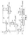
- FIG. 1 A first embodiment of the present is invention illustrated in Figure 1 which shows the integration of a gas turbine drive with an elevated pressure air separation unit (ASU).
- Ambient air in line 1 is compressed in multistage air compressor 3 to provide elevated pressure air in line 5 at 140 to 490 psia (965-1000 kPa) from the final compressor stage and medium pressure air in line 7 at 40 to 440 psia (275-3025 kPa) from an intermediate compressor stage.
- Compressor 3 can be an adiabatic or intercooled machine. Elevated pressure air in line 5 at 150 to 1200°F (65-650°C) is cooled in heat exchanger 9 by indirect heat exchange with nitrogen-rich byproduct stream in line 11 (later defined) to yield cooled elevated pressure air feed stream in line 13.
- This air feed stream is introduced into air separation system 15 which separates the air into an oxygen product in line 17 containing 80 to 99.8 vol% oxygen and byproduct nitrogen in line 11 containing less than 4 vol% oxygen at a pressure in the range of 40 to 440 psia (275-3025 kPa).
- Byproduct nitrogen in line 11 is heated in heat exchanger 9 as earlier described to provide heated byproduct nitrogen in line 18 which is combined with medium pressure air from line 7 to yield a combined gas stream in line 19.
- the molar flow ratio of byproduct nitrogen in line 18 to medium pressure air from line 7 is in the range of 1 to 10.
- the combined gas stream in line 19 is heated in heat exchanger 21 by indirect heat exchange with hot combustion gas in line 23 (later defined) to yield hot pressurized gas in line 25 at 1150 to 2600°F (620-1425°C) and 40 to 440 psia (275-3025 kPa).
- This hot gas stream is work expanded through gas turbine expander 27 to generate shaft work which is utilized directly to drive mechanically linked multistage air compressor 3.
- a portion of this shaft work can be used to drive an electric generator (not shown).
- Fuel in line 35 can be any gaseous, liquid, or solid carbonaceous fuel.
- the hot pressurized gas in line 25, which provides the motive fluid for gas turbine expander 27, typically contains a minimum of 85 vol% nitrogen with the balance being oxygen and argon.
- hot pressurized gas stream in line 25 contains no combustion products, and thus gas turbine expander 27 is not exposed to the carbon dioxide, sulfur oxides, water, and other components present in such combustion products. This is an important advantage of the present invention over integrated gas turbine-air separation systems of the prior art which use directly-fired gas turbines.
- the oxygen product in line 17 can be utilized in synthesis gas generator 41 to convert fuel in line 43 to synthesis gas product in line 45 containing hydrogen and carbon monoxide.
- Fuel in line 43 and fuel in line 35 can be the same, for example natural gas, or can be different carbonaceous components such as liquid hydrocarbons, petroleum residuum, coke, or coal. If desired, synthesis gas in line 45 can be used for fuel in line 35.
- Air separation system 15 typically is a cryogenic air separation system of any type known in the art.
- air separation system 15 preferably comprises an elevated pressure distillation system which operates in the range of 140 to 490 psia (965-3375 kPa).
- Nitrogen byproduct in line 11 typically does not require compression prior to combination with the pressurized air stream in line 7.
- air separation system 15 can utilize a pressure swing adsorption (PSA) process or a ceramic mixed conductor membrane process in conjunction with the indirectly-fired gas turbine system described above.
- PSA pressure swing adsorption
- ceramic mixed conductor membrane process in conjunction with the indirectly-fired gas turbine system described above.
- alternative heat exchange and heat integration steps would be required since PSA processes operate at near ambient temperatures and ceramic mixed conductor membrane processes operate at elevated temperatures.
- Each of these alternative embodiments, however, would utilize an indirectly-fired gas turbine.
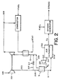
- FIG. 2 An alternative embodiment of the invention is illustrated in Fig. 2 in which the feed air is compressed in compressor 201 to provide pressurized air in line 203 which is divided into separate streams in lines 205 and 207.
- Pressurized air in line 205 is cooled by indirect heat exchange in heat exchanger 9 to yield cooled pressurized air 13 as earlier described.
- Air separation system 209 operates at lower pressures than air separation system 15 of Fig. 1, and byproduct nitrogen in line 211 is compressed in nitrogen compressor 213 before heating in heat exchanger 9.
- Pressurized air in line 207 passes through flow control valve 217 and is combined with heated pressurized nitrogen byproduct in line 219 to provide combined gas stream in line 19, which is heated in heat exchanger 21 as earlier described.
- the remaining features of the embodiment of Fig. 2 are identical to those of the embodiment of Fig. 1.
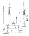
- FIG. 3 Another embodiment of the invention is illustrated in Fig. 3.
- air 301 is compressed in compressor 303 to provide pressurized air in line 305 which is combined with byproduct nitrogen from line 18 to provide the combined gas stream in line 19, which is heated in heat exchanger 21 as earlier described.
- This embodiment separates the compression duty of compressor 3 which provides pressurized air to air separation system 15 from the compression duty of compressor 301 which provides the pressurized air in line 305.
- Other features of the embodiment of Fig. 3 are identical to those of the embodiment of Fig. 1.
- FIG. 4 Another alternative embodiment of the invention is illustrated in Fig. 4.
- the heating and expansion of the nitrogen byproduct in line 18 and the pressurized air in line 19 are carried out separately.
- the two streams are heated in heat exchanger 401 by indirect heat exchange with a hot combustion gas stream from line 402 to provide a hot pressurized air stream in line 403 and a hot pressurized nitrogen byproduct stream in line 405.
- a portion of the pressurized air in line 207 can be introduced through valve 400 and combined with the nitrogen byproduct in line 18.
- the hot pressurized air and byproduct nitrogen streams are expanded in gas turbine expanders 407 and 409 respectively.
- Expander exhaust in line 411 is introduced in line 413 into combustor 415 to combust fuel 35, thereby generating the hot combustion gas stream in line 402.
- the embodiment of Fig. 4 is used when a traditional air-based combustion process is preferred in combustor 415.
- the hot combustion gas stream in line 402 will have a higher excess oxygen than the hot combustion gas stream in line 23 of the previously-described embodiments.
- Other features of the embodiment of Fig. 4 are identical to those of the embodiment of Fig. 1.
- the common element of all embodiments of the invention as described above is the use of an indirectly-heated motive fluid in the gas turbine expander wherein the motive fluid is a combination of pressurized air from the gas turbine compressor and nitrogen-rich byproduct gas from the air separation unit.
- the hot motive fluid contains no combustion products, and thus gas turbine expander is not exposed to the carbon dioxide, sulfur oxides, water, and other components present in such combustion products. This is an important advantage of the present invention over integrated gas turbine-air separation systems of the prior art.
- the availability of a process unit is defined as the percentage of time in a given time period during which the process unit is operational. During the remaining percentage of time, the process unit is shut down for maintenance and repairs.
- the overall availability of the system is determined by the lowest availability of the individual process units. It is therefore desirable to improve the performance of the individual unit having the lowest availability in order to improve the overall availability of the integrated operating system.
- the availability of a typical cryogenic air separation unit excluding the compressor system is greater than 99%.
- the availability of a gas turbine is generally lower than that of a cryogenic air separation unit, and so the overall availability of an integrated gas turbine/air separation system will be dictated by the availability of the gas turbine system.
- An indirectly-fired gas turbine will have a higher availability than a directly-fired gas turbine. Therefore the integrated indirectly-fired gas turbine/air separation system of the present invention will have a higher availability than an integrated directly-fired gas turbine/air separation system of the prior art.
- the air separation unit is an elevated pressure cryogenic dual-column distillation system as described in US-A-5,081,845 with an oxygen production capacity of 5000 short tons per day (STPD) (4250 tonnes per day).
- the gas turbine unit has a pressure ration of 12.3 to 1 with intermediate air extraction at a pressure ration of 6.6 to 1.
- Combustor 37 is fired by methane.
- Table 1 A summary of the simulation is given in Table 1 for an expansion turbine inlet temperature of 1912°F (1044°C).
- Example 1 The simulation of Example 1 was repeated using a cryogenic dual-column distillation system based on the process as described in described in US-A-5,081,845 but operating with a low pressure air feed and having an oxygen production capacity of 5000 short tons per day (STPD) (4250 tonnes per day).
- STPD short tons per day
- Table 2 A summary of the simulation is given in Table 2 for an expansion turbine inlet temperature of 2418°F (1326°C).
- Example 1 The simulation of Example 1 was repeated for other expansion turbine inlet temperatures between 1100°F (590°C) and 1900°F (1040°C).
- the heat rate defined as the heat input to the gas turbine combustor (BTU/h; KJ/h) divided by the gas turbine output at the shaft (KW), was determined for the present invention at various expansion turbine inlet temperatures.
- the heat rate is a measure of the system efficiency in converting heat energy into mechanical energy having the units of BTU/KWH (KJ/KWH) wherein a lower heat rate corresponds to a higher system efficiency.
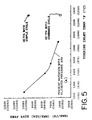
- FIG. 5 A plot of heat rate vs turbine inlet temperature for the above information is given in Fig. 5. As the turbine inlet temperature is reduced for the present invention, the heat rate increases and the system efficiency decreases. Lower turbine inlet temperatures are accompanied by less severe operating conditions for heat exchanger 21 of Fig. 1. At temperatures above 1500°F (815°C), ceramic or special metal alloy heat exchanger components typically are required, whereas more conventional materials and heat exchanger designs can be used at lower temperatures.
- the information plotted on Fig. 5 shows that the system of the present invention compares favorably in heat rate with the conventional directly-fired combined cycle GE 7FA system.
- the cycle of the present invention would require a costly ceramic or special alloy metal heat exchanger for heating the turbine inlet gas above 1500°F (815°C), the heat recovery steam generator and steam turbine of the directly-fired combined cycle system would not be required.
- the present invention compares favorably in heat rate with the directly-fired simple cycle GE 7FA system (no steam cycle). In all cases the availability of the system of the present invention would be higher than that of the conventional directly-fired system.
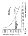
- Example 3 was repeated using the low pressure air separation cycle of Example 2, and the results are given in Fig. 6.
- the heat rate vs turbine inlet temperature plot in this case shows a somewhat less efficient system than that of Example 3, but the conclusions and comparisons of the present invention with the conventional directly-fired gas turbine system are the same.
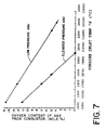
- Fig. 7 is a plot of the oxygen content of the hot combustion gas from combustor 37 (stream 23) vs the expansion turbine inlet temperature (stream 25).
- a minimum oxygen content in the combustor outlet of about 2 vol% is required to ensure complete combustion of fuel in the combustor.
- catalytic combustion in combustor 37 would be required.
- the elevated pressure air separation cycle of Example 1 can be utilized with turbine inlet temperatures up to 1800°F (980°C) without the need for catalytic combustion.
- the low pressure air separation cycle of Example 2 can be utilized with turbine inlet temperatures up to 2600°F (1425°C) without the need for catalytic combustion.
- Fig. 7 is useful for design purposes when selecting a turbine inlet temperature.
- the present invention uses an indirectly-fired gas turbine system to provide compressed air feed for an air separation system in applications where high driver availability is required.
- the invention integrates an indirectly-fired gas turbine with the air separation system for the production of oxygen with efficient utilization of the nitrogen-rich byproduct as a portion of the indirectly-heated gas turbine motive gas.
- the present invention improves the availability and reliability of gas turbine drivers for air separation systems, and is particularly useful in locations where electric drive for the air separation system is not feasible. In such locations, which may be remote from industrially-developed areas and lack reliable electric power grids, this high availability of the integrated gas turbine/air separation system is particularly important.
- the invention is also useful for very large air separation systems for which standalone electric motors and air compressors are not available.
Landscapes
- Engineering & Computer Science (AREA)
- Mechanical Engineering (AREA)
- General Engineering & Computer Science (AREA)
- Physics & Mathematics (AREA)
- Thermal Sciences (AREA)
- Chemical & Material Sciences (AREA)
- Combustion & Propulsion (AREA)
- Separation By Low-Temperature Treatments (AREA)
- Engine Equipment That Uses Special Cycles (AREA)
Claims (20)
- Procédé de production d'oxygène consistant à :(i) compresser de l'air afin d'obtenir un premier et second courants d'air pressurisé ;(ii) séparer le premier courant d'air pressurisé en un courant de produit suroxygéné et un produit de sous-produit sur-nitrogéné ;(iii) chauffer le courant de sous-produit sur-nitrogéné et le second courant d'air pressurisé afin d'obtenir un courant de gaz pressurisé chaud par échange de chaleur indirecte avec un courant de produit chaud produit par la combustion d'un carburant dans un foyer de combustion ;(iv) expanser le courant de gaz pressurisé chaud afin de produire une puissance de travail et un courant de décharge d'expanseur à pression réduite ; et(v) utiliser au moins une partie de la puissance de travail afin d'obtenir une puissance pour la compression d'air (i), caractérisé en ce que la combustion du carburant est effectuée par le courant de décharge d'expanseur à pression réduite contenant l'air afin d'obtenir le courant de produit chaud.
- Procédé de la revendication 1, dans lequel le courant de sous-produit sur-nitrogéné est combiné avec le second courant d'air pressurisé avant l'échange de chaleur indirecte (iii).
- Procédé de la revendication 2, dans lequel le courant de sous-produit sur-nitrogéné est compressé avant la combinaison avec le second courant d'air pressurisé;
- Procédé de la revendication 1, dans lequel le courant de sous-produit sur-nitrogéné et le second courant d'air pressurisé effectuent séparément un échange de chaleur indirecte (iii) et les courants de gaz pressurisé chaud de résultat sont expansés séparément.
- Procédé de la revendication 4, dans lequel la puissance de travail qui fournit une puissance pour la compression d'air (i) est obtenue par l'expansion d'à la fois le courant de sous-produit sur-nitrogéné et le second courant d'air pressurisé.
- Procédé de la revendication 4 ou 5, dans lequel l'échange de chaleur indirecte séparé du courant de sous - produit sur-nitrogéné et du second courant d'air pressurisé est accompli par échange de chaleur indirecte classique avec le même courant de produit chaud.
- Procédé selon l'une quelconque des revendications précédentes, dans lequel le premier et le second courants d'air pressurisé sont obtenus en compressant l'air et en divisant le courant d'air compressé de résultat en un premier et un second courants d'air pressurisé.
- Procédé selon l'une quelconque des revendications 1 à 6, dans lequel le premier et le second courant d'eir pressurisé sont obtenus en compressant l'air dans un compresseur d'air à étages multiples, en retirant l'air compressé d'un étage final du compresseur afin d'obtenir le premier courant d'air pressurisé, et en retirant l'air compressé à un étage intermédiaire du compresseur afin d'obtenir le second courant d'air pressurisé.
- Procédé selon l'une quelconque des revendications 1 à 8, dans lequel le premier et le second courants d'air pressurisé sont obtenus en présurissant l'air dans un premier compresseur d'air afin d'obtenir le premier courant d'air pressurisé et en compressant l'air dans un second compresseur d'air afin d'obtenir le second courant d'air pressurisé.
- Procédé selon l'une quelconque des revendications précédentes, dans lequel le premier courant d'air pressurisé a un débit plus important que le second courant d'air pressurisé.
- Procédé de la revendication 10, dans lequel le taux de débit molaire du courant de sous-produit sur-nitrogéné au second courant d'air pressurisé est compris entre 1 et 10.
- Procédé selon l'une quelconque des revendications précédentes, dans lequel l'air est ajouté au courant de décharge d'expanseur à pression réduite contenant l'air avant la combustion.
- Procédé selon l'une quelconque des revendications précédentes, dans lequel le courant de produit suroxygéné est utilisé pour gazifier un produit de départ carboné afin de produire un gaz de synthèse comprenant du monoxyde de carbone et d'hydrogène.
- Procédé de la revendication 13, dans lequel une partie du gaz de synthèse fournit au moins une partie du carburant du foyer de combustion.
- Procédé selon l'une quelconque des revendications précédentes, dans lequel la séparation du premier courant d'air pressurisé en un courant de produit suroxygéné et un courant de sous-produit sur-nitrogéné est accompli par distillation cryogénique.
- Procédé selon l'une quelconque des revendications précédentes, dans lequel une partie de la puissance de travail est utilisée pour produire de l'énergie électrique.
- Dispositif de production d'oxygène par un procédé comme défini à la revendication 1, lequel dispositif comprend
un moyen de compression (3) pour comprimer l'air (1) afin d'obtenir un premier et un second courants d'air pressurisé (5, 7) ;
un moyen de séparation d'air (15) pour séparer le premier courant d'air pressurisé (5) en un courant de produit suroxygéné (17) et un courant de sous-produit sur-nitrogéné (11) ;
un moyen d'échange de chaleur (21) pour chauffer le courant de sous-produit sur-nitrogéné (11) et le second courant d'air pressurisé (7) par échange de chaleur indirecte avec un courant de produit chaud (23) pour obtenir un courant de gaz pressurisé chaud (25) ;
un moyen d'expansion (27) pour expanser le courant de gaz pressurisé chaud afin de produire une puissance de travail qui fournit une puissance audits moyens de compression (3) et un courant de décharge d'expanseur à pression réduite (29) ; et
un foyer de combustion (37) pour effectuer la combustion d'un carburant (35) afin d'obtenir ledit ou lesdits courant(s) de produit chaud (23, caractérisé en ce que les moyens (33) sont fournis afin d'alimenter le foyer de combustion (37) avec le courant de décharge d'expanseur à pression réduite (29). - Dispositif de la revendication 17, comprenant un moyen (18) pour combiner le courant de sous-produit sur-nitrogéné (11) avec le second courant d'air pressurisé (7) avant le moyen d'échange de chaleur (21).
- Dispositif de la revendication 18, comprenant un moyen (213) pour compresser le courant de sous-produit sur-nitrogéné (11) avant la combinaison avec le second courant d'air pressurisé (7).
- Dispositif de la revendication 17, dans lequel le courant de sous-produit sur-nitrogéné (11) et le second courant d'air pressurisé (7) effectuent un échange de chaleur indirecte séparément dans le moyen d'échange de chaleur (401) et le moyen d'expansion comprend des expanseurs séparés (405, 416) pour les courants de produit chaud résultants.
Applications Claiming Priority (2)
| Application Number | Priority Date | Filing Date | Title |
|---|---|---|---|
| US83219 | 1998-05-22 | ||
| US09/083,219 US5979183A (en) | 1998-05-22 | 1998-05-22 | High availability gas turbine drive for an air separation unit |
Publications (3)
| Publication Number | Publication Date |
|---|---|
| EP0959314A2 EP0959314A2 (fr) | 1999-11-24 |
| EP0959314A3 EP0959314A3 (fr) | 2000-07-19 |
| EP0959314B1 true EP0959314B1 (fr) | 2004-07-07 |
Family
ID=22176941
Family Applications (1)
| Application Number | Title | Priority Date | Filing Date |
|---|---|---|---|
| EP99303843A Expired - Lifetime EP0959314B1 (fr) | 1998-05-22 | 1999-05-18 | Indirekt befeuerte Gasturbine integriert in einer Luftzerlegungsanlage |
Country Status (3)
| Country | Link |
|---|---|
| US (1) | US5979183A (fr) |
| EP (1) | EP0959314B1 (fr) |
| DE (1) | DE69918492T2 (fr) |
Families Citing this family (38)
| Publication number | Priority date | Publication date | Assignee | Title |
|---|---|---|---|---|
| GB0025150D0 (en) * | 2000-10-13 | 2000-11-29 | Air Prod & Chem | A process and apparatus for the production of synthesis gas |
| US6508053B1 (en) * | 1999-04-09 | 2003-01-21 | L'air Liquide-Societe Anonyme A'directoire Et Conseil De Surveillance Pour L'etude Et L'exploitation Des Procedes Georges Claude | Integrated power generation system |
| US6263659B1 (en) * | 1999-06-04 | 2001-07-24 | Air Products And Chemicals, Inc. | Air separation process integrated with gas turbine combustion engine driver |
| US6256994B1 (en) * | 1999-06-04 | 2001-07-10 | Air Products And Chemicals, Inc. | Operation of an air separation process with a combustion engine for the production of atmospheric gas products and electric power |
| FR2803221B1 (fr) * | 1999-12-30 | 2002-03-29 | Air Liquide | Procede et installation de separation d'air |
| FR2806755B1 (fr) * | 2000-03-21 | 2002-09-27 | Air Liquide | Procede et installation de generation d'energie utilisant un appareil de separation d'air |
| US6513318B1 (en) | 2000-11-29 | 2003-02-04 | Hybrid Power Generation Systems Llc | Low emissions gas turbine engine with inlet air heating |
| DE10111428A1 (de) * | 2001-03-09 | 2002-09-12 | Linde Ag | Verfahren und Vorrichtung zur Zerlegung eines Gasgemischs mit Notbetrieb |
| FR2825754B1 (fr) * | 2001-06-08 | 2004-02-27 | Air Liquide | Procede et installation de production d'energie au moyen d'une turbine a gaz associee a une unite de separation d'air |
| US6568207B1 (en) * | 2002-01-18 | 2003-05-27 | L'air Liquide-Societe Anonyme A Directoire Et Conseil De Surveillance Pour L'etude Et L'exploitation Des Procedes Georges Claude | Integrated process and installation for the separation of air fed by compressed air from several compressors |
| HUE059355T2 (hu) * | 2002-10-10 | 2022-11-28 | Lpp Comb Llc | Eljárás folyékony tüzelõanyagok elpárologtatására égetés céljára |
| FR2851330B1 (fr) * | 2003-02-13 | 2006-01-06 | Air Liquide | Procede et installation de production sous forme gazeuse et sous haute pression d'au moins un fluide choisi parmi l'oxygene, l'argon et l'azote par distillation cryogenique de l'air |
| US6694776B1 (en) * | 2003-05-14 | 2004-02-24 | Praxair Technology, Inc. | Cryogenic air separation system for producing oxygen |
| WO2005031136A1 (fr) * | 2003-09-30 | 2005-04-07 | Bhp Billiton Innovation Pty Ltd | Generation de puissance |
| FR2862004B3 (fr) * | 2003-11-10 | 2005-12-23 | Air Liquide | Procede et installation d'enrichissement d'un flux gazeux en l'un de ses constituants |
| CN100357685C (zh) * | 2004-10-28 | 2007-12-26 | 苏州市兴鲁空分设备科技发展有限公司 | 一种空气分离的方法和装置 |
| CN100357684C (zh) * | 2004-10-28 | 2007-12-26 | 苏州市兴鲁空分设备科技发展有限公司 | 一种空气分离的方法和装置 |
| DE102004057637A1 (de) * | 2004-11-30 | 2006-06-01 | Reinhard Eckert | Verfahren zum Betreiben einer Heissluftmaschine und Heissluftmaschine zur Durchführung des Verfahrens |
| JP4920597B2 (ja) | 2004-12-08 | 2012-04-18 | エル・ピー・ピー コンバスション エル・エル・シー | 液体炭化水素燃料を調整する方法および装置 |
| US7717955B2 (en) * | 2005-02-28 | 2010-05-18 | Medtronic, Inc. | Conformable prosthesis for implanting two-piece heart valves and methods for using them |
| DE102005026534B4 (de) * | 2005-06-08 | 2012-04-19 | Man Diesel & Turbo Se | Dampferzeugungsanlage |
| US8075646B2 (en) * | 2006-02-09 | 2011-12-13 | Siemens Energy, Inc. | Advanced ASU and HRSG integration for improved integrated gasification combined cycle efficiency |
| US8529646B2 (en) | 2006-05-01 | 2013-09-10 | Lpp Combustion Llc | Integrated system and method for production and vaporization of liquid hydrocarbon fuels for combustion |
| US20090301100A1 (en) * | 2006-06-01 | 2009-12-10 | Bhp Billiton Innovation Pty. Ltd. | Power Generation |
| AU2007262669A1 (en) * | 2006-06-23 | 2007-12-27 | Bhp Billiton Innovation Pty Ltd | Power generation |
| US7686570B2 (en) * | 2006-08-01 | 2010-03-30 | Siemens Energy, Inc. | Abradable coating system |
| US7947115B2 (en) * | 2006-11-16 | 2011-05-24 | Siemens Energy, Inc. | System and method for generation of high pressure air in an integrated gasification combined cycle system |
| FR2928414B1 (fr) * | 2008-03-07 | 2011-03-25 | Sorea | Dispositif de production d'energie a partir de biomasse |
| US8865608B2 (en) * | 2009-02-27 | 2014-10-21 | Uop Llc | Turndown thermocompressor design for continuous catalyst recovery |
| US8418472B2 (en) * | 2009-05-22 | 2013-04-16 | General Electric Company | Method and system for use with an integrated gasification combined cycle plant |
| US8881530B2 (en) * | 2010-09-02 | 2014-11-11 | General Electric Company | Fuel heating system for startup of a combustion system |
| GB201105823D0 (en) * | 2011-04-06 | 2011-05-18 | Liquid Gas Eqipment Ltd | Method of cooling boil off gas and an apparatus therefor |
| SG194143A1 (en) | 2011-04-19 | 2013-11-29 | Babcock Integrated Technology Ltd | Method of cooling boil off gas and an apparatus therefor |
| US20130025866A1 (en) * | 2011-07-25 | 2013-01-31 | Chevron U.S.A. Inc. | Integrated process utilizing nitrogen and carbon dioxide streams for enhanced oil recovery |
| US9327243B2 (en) * | 2012-08-24 | 2016-05-03 | The Boeing Company | Aircraft fuel tank flammability reduction methods and systems |
| US9702300B2 (en) | 2014-02-12 | 2017-07-11 | King Fahd University Of Petroleum And Minerals | Applications of oxy-fuel combustion technology into gas turbine combustors and ion transport membrane reactors |
| DE102016107468B9 (de) * | 2016-04-22 | 2017-12-21 | Fritz Winter Eisengiesserei Gmbh & Co. Kg | Verfahren und Anlage zur Nutzung eines von einer Gaszerlegeeinrichtung bereitgestellten Zielgases |
| US11702981B1 (en) * | 2022-04-20 | 2023-07-18 | Raytheon Technologies Corporation | Turbine engine bleed waste heat recovery |
Family Cites Families (28)
| Publication number | Priority date | Publication date | Assignee | Title |
|---|---|---|---|---|
| US2268270A (en) * | 1938-12-13 | 1941-12-30 | Sulzer Ag | Gas turbine plant |
| US3731495A (en) * | 1970-12-28 | 1973-05-08 | Union Carbide Corp | Process of and apparatus for air separation with nitrogen quenched power turbine |
| IL36741A (en) * | 1971-04-30 | 1974-11-29 | Zakon T | Method for the separation of gaseous mixtures with recuperation of mechanical energy and apparatus for carrying out this method |
| US4049299A (en) * | 1973-03-12 | 1977-09-20 | Agence Nationale De Valorisation De La Recherche (Anvar) | Anti-polluting power plant using compressors and gas turbines |
| US3871172A (en) * | 1974-01-03 | 1975-03-18 | Chemical Construction Corp | Process with fluidized combustor and fluidized heat exchanger for air |
| IL44298A (en) * | 1974-02-27 | 1978-10-31 | Tsadok Zakon | Method for the separation of air with recuperation of mechanical energy |
| DE2503193A1 (de) * | 1975-01-27 | 1976-07-29 | Linde Ag | Verfahren zur herstellung eines heizgases durch druckvergasung kohlenstoffhaltiger brennstoffe |
| DE2835852C2 (de) * | 1978-08-16 | 1982-11-25 | Kraftwerk Union AG, 4330 Mülheim | Kombinierte Gas-Dampfkraftanlage mit einer Vergasungseinrichtung für den Brennstoff |
| US4545787A (en) * | 1984-07-30 | 1985-10-08 | Air Products And Chemicals, Inc. | Process for producing by-product oxygen from turbine power generation |
| US4751814A (en) * | 1985-06-21 | 1988-06-21 | General Electric Company | Air cycle thermodynamic conversion system |
| EP0211335B1 (fr) * | 1985-08-05 | 1988-05-11 | Siemens Aktiengesellschaft | Centrale à cycle combiné |
| US4785621A (en) * | 1987-05-28 | 1988-11-22 | General Electric Company | Air bottoming cycle for coal gasification plant |
| GB8824216D0 (en) * | 1988-10-15 | 1988-11-23 | Boc Group Plc | Air separation |
| US5035727A (en) * | 1990-05-24 | 1991-07-30 | Air Products And Chemicals, Inc. | Oxygen extraction from externally fired gas turbines |
| US5081845A (en) * | 1990-07-02 | 1992-01-21 | Air Products And Chemicals, Inc. | Integrated air separation plant - integrated gasification combined cycle power generator |
| US5165239A (en) * | 1991-06-03 | 1992-11-24 | The United States Of America As Represented By The United States Department Of Energy | Water augmented indirectly-fired gas turbine systems and method |
| GB9123381D0 (en) * | 1991-11-04 | 1991-12-18 | Boc Group Plc | Air separation |
| US5459994A (en) * | 1993-05-28 | 1995-10-24 | Praxair Technology, Inc. | Gas turbine-air separation plant combination |
| US5406786A (en) * | 1993-07-16 | 1995-04-18 | Air Products And Chemicals, Inc. | Integrated air separation - gas turbine electrical generation process |
| ES2116518T3 (es) * | 1993-12-17 | 1998-07-16 | Air Prod & Chem | Produccion integrada de oxigeno y energia electrica. |
| US5565017A (en) * | 1993-12-17 | 1996-10-15 | Air Products And Chemicals, Inc. | High temperature oxygen production with steam and power generation |
| US5516359A (en) * | 1993-12-17 | 1996-05-14 | Air Products And Chemicals, Inc. | Integrated high temperature method for oxygen production |
| US5643354A (en) * | 1995-04-06 | 1997-07-01 | Air Products And Chemicals, Inc. | High temperature oxygen production for ironmaking processes |
| US5501078A (en) * | 1995-04-24 | 1996-03-26 | Praxair Technology, Inc. | System and method for operating an integrated gas turbine and cryogenic air separation plant under turndown conditions |
| US5562754A (en) * | 1995-06-07 | 1996-10-08 | Air Products And Chemicals, Inc. | Production of oxygen by ion transport membranes with steam utilization |
| US5706675A (en) * | 1995-08-18 | 1998-01-13 | G & A Associates | High efficiency oxygen/air separation system |
| US5740673A (en) * | 1995-11-07 | 1998-04-21 | Air Products And Chemicals, Inc. | Operation of integrated gasification combined cycle power generation systems at part load |
| US5666823A (en) * | 1996-01-31 | 1997-09-16 | Air Products And Chemicals, Inc. | High pressure combustion turbine and air separation system integration |
-
1998
- 1998-05-22 US US09/083,219 patent/US5979183A/en not_active Expired - Lifetime
-
1999
- 1999-05-18 EP EP99303843A patent/EP0959314B1/fr not_active Expired - Lifetime
- 1999-05-18 DE DE69918492T patent/DE69918492T2/de not_active Expired - Fee Related
Also Published As
| Publication number | Publication date |
|---|---|
| DE69918492T2 (de) | 2005-08-18 |
| DE69918492D1 (de) | 2004-08-12 |
| US5979183A (en) | 1999-11-09 |
| EP0959314A2 (fr) | 1999-11-24 |
| EP0959314A3 (fr) | 2000-07-19 |
Similar Documents
| Publication | Publication Date | Title |
|---|---|---|
| EP0959314B1 (fr) | Indirekt befeuerte Gasturbine integriert in einer Luftzerlegungsanlage | |
| US10054046B2 (en) | System and method for high efficiency power generation using a nitrogen gas working fluid | |
| JP2853681B2 (ja) | 統合ガスタービン・空気分離装置を部分負荷で運転させるための方法 | |
| EP0622535B1 (fr) | Utilisation de nitrogène d'une installation de séparation d'air pour le refroidissement de l'air fourni au compresseur d'une turbine à gaz pour augmenter le rendement | |
| US6256994B1 (en) | Operation of an air separation process with a combustion engine for the production of atmospheric gas products and electric power | |
| US7654320B2 (en) | System and method for processing a mixture of hydrocarbon and CO2 gas produced from a hydrocarbon reservoir | |
| JP2516851B2 (ja) | 一貫式ガス化組合せサイクル電力発生方法 | |
| JP6153231B2 (ja) | 低エミッションタービンシステムにおける二酸化炭素捕捉システム及び方法 | |
| US5901547A (en) | Operation method for integrated gasification combined cycle power generation system | |
| US6612113B2 (en) | Integrated method of air separation and of energy generation and plant for the implementation of such a method | |
| CA2792061A1 (fr) | Procedes de generation de puissance par oxy-combustion au moyen d'un combustible a faible valeur calorifique | |
| US20090229239A1 (en) | Integrated Pressurized Steam Hydrocarbon Reformer and Combined Cycle Process | |
| US20100024432A1 (en) | Method for improved efficiency for IGCC | |
| US8191349B2 (en) | System and method for low emissions combustion | |
| KR100194554B1 (ko) | 하절기 출력감소 방지가 가능한 석탄가스화 복합발전 시스템 및 석탄가스화 복합발전 시스템의 하절기 출력감소 방지방법 | |
| AU649907B2 (en) | Integrated air separation plant - integrated gasification combined cycle power generator | |
| KR100355309B1 (ko) | 산소분리장치의 잉여질소를 이용한 석탄가스화 복합발전시스템 | |
| Smith et al. | Air separation unit integration for alternative fuel projects | |
| Gambini et al. | Advanced H2/Air Cycles Based on Coal Gasification | |
| Gambini et al. | Comparative Analysis of Advanced H2/Air Cycle Power Plants Based on Different Hydrogen Production Systems From Fossil Fuels | |
| Hendriks | Carbon dioxide recovery from an integrated coal gasifier, combined cycle plant using membrane separation and a CO2 gas turbine | |
| MXPA96005375A (en) | Operation of systems for generation of energy with combined cycle of integrated gasification at parc load | |
| HK1187968B (en) | System and method for high efficiency power generation using a nitrogen gas working fluid |
Legal Events
| Date | Code | Title | Description |
|---|---|---|---|
| PUAI | Public reference made under article 153(3) epc to a published international application that has entered the european phase |
Free format text: ORIGINAL CODE: 0009012 |
|
| AK | Designated contracting states |
Kind code of ref document: A2 Designated state(s): BE DE ES FR GB IT NL |
|
| AX | Request for extension of the european patent |
Free format text: AL;LT;LV;MK;RO;SI |
|
| PUAL | Search report despatched |
Free format text: ORIGINAL CODE: 0009013 |
|
| AK | Designated contracting states |
Kind code of ref document: A3 Designated state(s): AT BE CH CY DE DK ES FI FR GB GR IE IT LI LU MC NL PT SE |
|
| AX | Request for extension of the european patent |
Free format text: AL;LT;LV;MK;RO;SI |
|
| RIC1 | Information provided on ipc code assigned before grant |
Free format text: 7F 25J 3/04 A, 7F 02C 1/04 B |
|
| 17P | Request for examination filed |
Effective date: 20000911 |
|
| AKX | Designation fees paid |
Free format text: BE DE ES FR GB IT NL |
|
| 17Q | First examination report despatched |
Effective date: 20020503 |
|
| GRAP | Despatch of communication of intention to grant a patent |
Free format text: ORIGINAL CODE: EPIDOSNIGR1 |
|
| GRAS | Grant fee paid |
Free format text: ORIGINAL CODE: EPIDOSNIGR3 |
|
| GRAA | (expected) grant |
Free format text: ORIGINAL CODE: 0009210 |
|
| AK | Designated contracting states |
Kind code of ref document: B1 Designated state(s): BE DE ES FR GB IT NL |
|
| PG25 | Lapsed in a contracting state [announced via postgrant information from national office to epo] |
Ref country code: NL Free format text: LAPSE BECAUSE OF FAILURE TO SUBMIT A TRANSLATION OF THE DESCRIPTION OR TO PAY THE FEE WITHIN THE PRESCRIBED TIME-LIMIT Effective date: 20040707 Ref country code: IT Free format text: LAPSE BECAUSE OF FAILURE TO SUBMIT A TRANSLATION OF THE DESCRIPTION OR TO PAY THE FEE WITHIN THE PRESCRIBED TIME-LIMIT;WARNING: LAPSES OF ITALIAN PATENTS WITH EFFECTIVE DATE BEFORE 2007 MAY HAVE OCCURRED AT ANY TIME BEFORE 2007. THE CORRECT EFFECTIVE DATE MAY BE DIFFERENT FROM THE ONE RECORDED. Effective date: 20040707 Ref country code: BE Free format text: LAPSE BECAUSE OF FAILURE TO SUBMIT A TRANSLATION OF THE DESCRIPTION OR TO PAY THE FEE WITHIN THE PRESCRIBED TIME-LIMIT Effective date: 20040707 |
|
| REG | Reference to a national code |
Ref country code: GB Ref legal event code: FG4D |
|
| REF | Corresponds to: |
Ref document number: 69918492 Country of ref document: DE Date of ref document: 20040812 Kind code of ref document: P |
|
| PG25 | Lapsed in a contracting state [announced via postgrant information from national office to epo] |
Ref country code: ES Free format text: LAPSE BECAUSE OF FAILURE TO SUBMIT A TRANSLATION OF THE DESCRIPTION OR TO PAY THE FEE WITHIN THE PRESCRIBED TIME-LIMIT Effective date: 20041018 |
|
| NLV1 | Nl: lapsed or annulled due to failure to fulfill the requirements of art. 29p and 29m of the patents act | ||
| ET | Fr: translation filed | ||
| PLBE | No opposition filed within time limit |
Free format text: ORIGINAL CODE: 0009261 |
|
| STAA | Information on the status of an ep patent application or granted ep patent |
Free format text: STATUS: NO OPPOSITION FILED WITHIN TIME LIMIT |
|
| PGFP | Annual fee paid to national office [announced via postgrant information from national office to epo] |
Ref country code: FR Payment date: 20050517 Year of fee payment: 7 |
|
| 26N | No opposition filed |
Effective date: 20050408 |
|
| PGFP | Annual fee paid to national office [announced via postgrant information from national office to epo] |
Ref country code: GB Payment date: 20060406 Year of fee payment: 8 |
|
| PGFP | Annual fee paid to national office [announced via postgrant information from national office to epo] |
Ref country code: DE Payment date: 20060531 Year of fee payment: 8 |
|
| GBPC | Gb: european patent ceased through non-payment of renewal fee |
Effective date: 20070518 |
|
| REG | Reference to a national code |
Ref country code: FR Ref legal event code: ST Effective date: 20080131 |
|
| PG25 | Lapsed in a contracting state [announced via postgrant information from national office to epo] |
Ref country code: DE Free format text: LAPSE BECAUSE OF NON-PAYMENT OF DUE FEES Effective date: 20071201 |
|
| PG25 | Lapsed in a contracting state [announced via postgrant information from national office to epo] |
Ref country code: GB Free format text: LAPSE BECAUSE OF NON-PAYMENT OF DUE FEES Effective date: 20070518 |
|
| PG25 | Lapsed in a contracting state [announced via postgrant information from national office to epo] |
Ref country code: FR Free format text: LAPSE BECAUSE OF NON-PAYMENT OF DUE FEES Effective date: 20070531 |
|
| PG25 | Lapsed in a contracting state [announced via postgrant information from national office to epo] |
Ref country code: FR Free format text: LAPSE BECAUSE OF NON-PAYMENT OF DUE FEES Effective date: 20060531 |