EP0959320A1 - Dispositif de fixation pour un miroir de volée - Google Patents
Dispositif de fixation pour un miroir de volée Download PDFInfo
- Publication number
- EP0959320A1 EP0959320A1 EP99107739A EP99107739A EP0959320A1 EP 0959320 A1 EP0959320 A1 EP 0959320A1 EP 99107739 A EP99107739 A EP 99107739A EP 99107739 A EP99107739 A EP 99107739A EP 0959320 A1 EP0959320 A1 EP 0959320A1
- Authority
- EP
- European Patent Office
- Prior art keywords
- flanges
- tube
- collar
- mirror
- support
- Prior art date
- Legal status (The legal status is an assumption and is not a legal conclusion. Google has not performed a legal analysis and makes no representation as to the accuracy of the status listed.)
- Granted
Links
- 230000000295 complement effect Effects 0.000 claims abstract description 4
- 230000014759 maintenance of location Effects 0.000 claims 1
- 238000010304 firing Methods 0.000 description 6
- 230000000694 effects Effects 0.000 description 3
- 230000035882 stress Effects 0.000 description 2
- 238000003466 welding Methods 0.000 description 2
- 230000001133 acceleration Effects 0.000 description 1
- 230000003247 decreasing effect Effects 0.000 description 1
- 230000005489 elastic deformation Effects 0.000 description 1
- 239000000463 material Substances 0.000 description 1
- 239000002184 metal Substances 0.000 description 1
- 239000003380 propellant Substances 0.000 description 1
- 239000000779 smoke Substances 0.000 description 1
- 230000008961 swelling Effects 0.000 description 1
- 230000008646 thermal stress Effects 0.000 description 1
Images
Classifications
-
- F—MECHANICAL ENGINEERING; LIGHTING; HEATING; WEAPONS; BLASTING
- F41—WEAPONS
- F41G—WEAPON SIGHTS; AIMING
- F41G3/00—Aiming or laying means
- F41G3/32—Devices for testing or checking
- F41G3/323—Devices for testing or checking for checking the angle between the muzzle axis of the gun and a reference axis, e.g. the axis of the associated sighting device
Definitions
- the technical field of the invention is that of devices allowing the attachment of a flight mirror to a end of an artillery tube.
- fly mirrors The function of fly mirrors is to provide the artillery fire conduct the actual position of the end of the tube.
- the external ballistics of the projectile (therefore the precision of the shot) is linked to the actual position of the mouth of the tube.
- the accuracy of the shot will therefore be strongly affected by the arc of the tube and the firing line must know precisely the actual coordinates of the mouth of the tube to order an appropriate score.
- the fly mirror is a polished surface that receives a laser beam emitted from the fire line. This mirror reflects the ray, a sensor on the firing line receives the ray reflected and thus determines the actual position of the mouth of the tube as a function of the deviation measured.
- Known devices for fixing flight mirrors generally have fixing flanges surrounding the weapon barrel. They have the disadvantage of harm withstand the constraints due to shooting (recoil accelerations and vibrations), stresses all the stronger as the tube of the weapon generally comprises a muzzle brake which returns some of the propellants backwards, so towards the mirror. The radial and / or axial position of the mirror is is thus gradually modified and the shooting reference measured becomes false.
- the device according to the invention is of simple structure and robust and it ensures reliable positioning of the mirror stolen from the end of the barrel.
- the subject of the invention is a fixing device for a flight mirror at one end of a tube artillery, device comprising a mirror support comprising at least two flanges surrounding the barrel of the weapon and connected to each other by a first connecting means, device characterized in that the flanges are housed in the level of a groove of the tube and are linked in rotation to it via an obstacle, device comprising also a centering collar which fits in the groove, collar consisting of at least two jaws connected by a second connecting means, collar having a range conical cooperating with a complementary conical bearing fitted on the flanges so that the tightening of the second connecting means provides both axial support and radial of the flanges.
- the centering collar will comprise three identical jaws linked in pairs by screws.
- Each jaw may have transverse slots intended to facilitate its deformation.
- the first and second means of connection may have screws and conical washers arranged below the screw heads, washers allowing elastic radial deformation of the support and the collar.
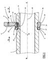
- a tube weapon 1 is shown partially in section longitudinal.
- the tube 1 carries a circular groove 2 intended to receive a support 3 of a flight mirror 4.
- the mirror 4 is constituted by a metal disc reflective which is fixed on the support 3 by a rod threaded 5.
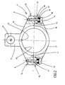
- the support 3 has two flanges 3a and 3b.
- the bridle upper 3a has an extension 6 on which is fixed the mirror 4 as well as lateral legs 7a, 7b which carry each with an internal thread 8.
- the lower flange 3b has lateral tabs 9a, 9b which each carry a bore 10 and a countersink 11. Screws 12 are introduced into the bores 10 to ensure, by through the internal threads 8, the joining of the two flanges 3a and 3b. Conical elastic washers 28 are mounted under the heads of the screws 12, in opposition two by two, and separated by a flat washer 29. A couple of appropriate tightening is given to each screw in order to leave a certain degree of deformation for conical washers. This mounting is intended to tie elastically the two flanges to allow slight swelling of the barrel which occurs when firing a projectile. A montage rigid, without washers allowing radial deformation, would create damaging stresses for screws or threads when firing a projectile. Screw 12 and washers 28.29 constitute the first means of connection of the two flanges 3a, 3b.
- the upper flange 3a also has a groove longitudinal 13 arranged on the internal cylindrical surface 15 of the flange 3a. This groove is intended to receive a key 14 which is also arranged in a housing 16 made at the bottom of the throat 2.
- the key 14 thus constitutes an obstacle which ensures the joining in rotation of the support 3 and the tube 1.
- the key a ball placed between support and tube and cooperating with appropriate impressions made on the support and tube.
- the support 3 also has a conical bearing convex 17 whose vertex A is located virtually on the axis 18 of tube 1 of the weapon and whose taper is oriented towards the front part F of the tube.
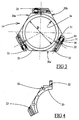
- the fixing device comprises also a centering collar 19 which is here constituted by three jaws 20a, 20b, 20c (see Figure 3) connected by a second connecting means constituted here by screws 21 and washers 30.31. All the jaws are identical and substantially cover an angular sector of 120 °. Each jaw has at one end a hole 22 intended to receive a screw head 21 and at its other end a thread 23 receiving the threaded part of another screw 21. As in the mounting of the flanges previously described, conical washers 30 and a flat washer 31 are arranged under the screw heads 21.
- each jaw is fixed to its two neighbors by one screw and tightening the three screws with an appropriate torque has the effect of gradually decreasing the diameter D by the internal bore 24 delimited by the assembled collar 19.
- the washers 30 also allow the tube to swell when firing a projectile.
- the collar 19 has a conical bearing 25 which is intended to cooperate with the complementary conical bearing 17 carried by the flanges 3a, 3b.
- the device according to the invention is mounted in the way next :
- the jaws 20a, 20b, 20c are then positioned with their conical bearing 25 in contact with the conical bearing 17.
- the screws 21 keep the jaws in the groove 2.
- the rear face of the collar 19 is also located blocked against the rear edge 27 of the groove 2.
- setting can resist the forces and vibrations caused by the firing of artillery.
- the sharing of the collar centering in three jaws allows to distribute the surfaces of contact between the conical bearings 25 and 17.
- a number of upper jaws improves the distribution of forces.
- each jaw 20 transverse slots 32 which facilitate elastic deformation of the jaws when tightening the screw 21 (see figure 4). This increases the tightening effect.
Landscapes
- Engineering & Computer Science (AREA)
- General Engineering & Computer Science (AREA)
- Lasers (AREA)
- Mutual Connection Of Rods And Tubes (AREA)
- Gripping Jigs, Holding Jigs, And Positioning Jigs (AREA)
Abstract
Description
- la figure 1 représente en coupe transversale un dispositif de fixation de miroir de volée disposé à l'extrémité d'un tube d'artillerie,
- la figure 2 est une vue des brides de miroir seules suivant la direction repérée par la flèche X à la figure 1,
- la figure 3 est une vue du collier de centrage seul suivant la direction repérée par la flèche Y à la figure 1,
- la figure 4 est une variante de réalisation d'une mâchoire du collier de centrage.
Claims (4)
- Dispositif de fixation pour un miroir de volée à une extrémité d'un tube d'artillerie, dispositif comprenant un support (3) de miroir (4) comportant au moins deux brides (3a,3b) entourant le tube (1) de l'arme et reliées l'une à l'autre par un premier moyen de liaison, dispositif caractérisé en ce que les brides (3a,3b) se logent au niveau d'une gorge (2) du tube et sont liées en rotation à celui-ci par l'intermédiaire d'un obstacle (14), dispositif comprenant également un collier (19) de centrage se logeant dans la gorge (2), collier constitué par au moins deux mâchoires (20) reliées par un deuxième moyen de liaison, collier présentant une portée conique (25) coopérant avec une portée conique complémentaire (17) aménagée sur les brides (3a,3b) de telle sorte que le serrage du deuxième moyen de liaison assure à la fois un maintien axial et radial des brides (3a,3b).
- Dispositif de fixation selon la revendication 1, caractérisé en ce que le collier de centrage comporte trois mâchoires identiques (20a,20b,20c) reliées deux à deux par des vis.
- Dispositif de fixation selon une des revendications 1 ou 2, caractérisé en ce que chaque mâchoire (20a,20b,20c) présente des fentes transversales (32) destinées à faciliter sa déformation.
- Dispositif de fixation selon une des revendications 1 à 3, caractérisé en ce que le premier et le deuxième moyen de liaison comprennent des vis (12,21) ainsi que des rondelles coniques (28,30) disposées en dessous des têtes de vis, rondelles autorisant une déformation radiale élastique du support (3) et du collier (19).
Applications Claiming Priority (2)
| Application Number | Priority Date | Filing Date | Title |
|---|---|---|---|
| FR9806350A FR2778736B1 (fr) | 1998-05-18 | 1998-05-18 | Dispositif de fixation pour un miroir de volee |
| FR9806350 | 1998-05-18 |
Publications (2)
| Publication Number | Publication Date |
|---|---|
| EP0959320A1 true EP0959320A1 (fr) | 1999-11-24 |
| EP0959320B1 EP0959320B1 (fr) | 2003-06-18 |
Family
ID=9526534
Family Applications (1)
| Application Number | Title | Priority Date | Filing Date |
|---|---|---|---|
| EP99107739A Expired - Lifetime EP0959320B1 (fr) | 1998-05-18 | 1999-04-19 | Dispositif de fixation pour un miroir de volée |
Country Status (5)
| Country | Link |
|---|---|
| US (1) | US6178648B1 (fr) |
| EP (1) | EP0959320B1 (fr) |
| DE (1) | DE69908861T2 (fr) |
| FR (1) | FR2778736B1 (fr) |
| ZA (1) | ZA993363B (fr) |
Families Citing this family (4)
| Publication number | Priority date | Publication date | Assignee | Title |
|---|---|---|---|---|
| US7896508B2 (en) * | 2002-06-10 | 2011-03-01 | Dyson William E | Gun mirror |
| DE102005031947A1 (de) * | 2005-07-08 | 2007-01-11 | Rheinmetall Waffe Munition Gmbh | Vorrichtung zur Befestigung eines auf bzw. an einem Körper zu befestigenden Teils |
| US20110000121A1 (en) * | 2007-06-13 | 2011-01-06 | Uhl Thomas N | Vision system |
| SE541616C2 (en) * | 2017-05-02 | 2019-11-12 | Saab Ab | Arrangement and method for aligning a sub-calibre barrel in a principal weapon |
Citations (2)
| Publication number | Priority date | Publication date | Assignee | Title |
|---|---|---|---|---|
| DE2950173A1 (de) * | 1979-12-13 | 1981-06-19 | Peter 5309 Meckenheim Bettermann | Verfahren und vorrichtung zur bestimmung des abgangsfehlerwinkels eines geschosses beim verlassen des waffenrohres |
| FR2504668A1 (fr) * | 1981-04-24 | 1982-10-29 | France Etat | Procede et dispositif d'asservissement d'une arme a une lunette de visee |
Family Cites Families (16)
| Publication number | Priority date | Publication date | Assignee | Title |
|---|---|---|---|---|
| US1668975A (en) * | 1928-05-08 | Eyepiece fob gun sights | ||
| US1227544A (en) * | 1916-01-31 | 1917-05-22 | Burr Lobdell | Gun-sight. |
| US1264133A (en) * | 1916-07-17 | 1918-04-23 | Ebenezer Reginald Morris | Rifle-periscope. |
| US1428115A (en) * | 1921-04-26 | 1922-09-05 | Perrin Arthur | Sight for firearms |
| US1501211A (en) * | 1922-02-09 | 1924-07-15 | Forin Alexander | Peep sight for shotguns |
| US2123273A (en) * | 1937-03-29 | 1938-07-12 | Winchester Repeating Arms Co | Removable mount for firearm sights |
| US2607993A (en) * | 1948-12-16 | 1952-08-26 | George C Mckay | Gun sight |
| US3260008A (en) * | 1964-08-03 | 1966-07-12 | Olin Mathieson | Sight for firearms |
| DE1703910B1 (de) * | 1968-07-27 | 1971-10-14 | Westinger & Altenburger | Wechselkorn fuer Handfeuerwaffe |
| US3863354A (en) * | 1974-01-17 | 1975-02-04 | Toivo Johannes Karppinen | Mirror sight for small firearms |
| US3945142A (en) * | 1974-08-02 | 1976-03-23 | Carl Walther, Sportwaffenfabrik | Mount for a sight on firearms |
| US4242825A (en) * | 1979-02-28 | 1981-01-06 | Sherry Miles deBoer | Firearm mechanism |
| US4776126A (en) * | 1987-08-10 | 1988-10-11 | Williams Paul D | Telescope mount for a firearm |
| US5442860A (en) * | 1993-07-15 | 1995-08-22 | Palmer; Michael R. | Portable reticle alingment device for firearms |
| SE9404198L (sv) * | 1994-12-02 | 1995-12-18 | Polarit Foersaeljnings Ab | Sikte för handeldvapen |
| US5884884A (en) * | 1996-10-31 | 1999-03-23 | Litton Systems, Inc. | Mounting assembly for image intensifier tube in optical sight |
-
1998
- 1998-05-18 FR FR9806350A patent/FR2778736B1/fr not_active Expired - Fee Related
-
1999
- 1999-04-19 EP EP99107739A patent/EP0959320B1/fr not_active Expired - Lifetime
- 1999-04-19 DE DE69908861T patent/DE69908861T2/de not_active Expired - Lifetime
- 1999-05-10 US US09/307,762 patent/US6178648B1/en not_active Expired - Fee Related
- 1999-05-17 ZA ZA9903363A patent/ZA993363B/xx unknown
Patent Citations (2)
| Publication number | Priority date | Publication date | Assignee | Title |
|---|---|---|---|---|
| DE2950173A1 (de) * | 1979-12-13 | 1981-06-19 | Peter 5309 Meckenheim Bettermann | Verfahren und vorrichtung zur bestimmung des abgangsfehlerwinkels eines geschosses beim verlassen des waffenrohres |
| FR2504668A1 (fr) * | 1981-04-24 | 1982-10-29 | France Etat | Procede et dispositif d'asservissement d'une arme a une lunette de visee |
Also Published As
| Publication number | Publication date |
|---|---|
| US6178648B1 (en) | 2001-01-30 |
| DE69908861T2 (de) | 2004-05-06 |
| DE69908861D1 (de) | 2003-07-24 |
| ZA993363B (en) | 1999-11-10 |
| FR2778736A1 (fr) | 1999-11-19 |
| EP0959320B1 (fr) | 2003-06-18 |
| FR2778736B1 (fr) | 2000-06-16 |
Similar Documents
| Publication | Publication Date | Title |
|---|---|---|
| EP1092939A1 (fr) | Dispositif de fixation d'un culot obturateur sur un étui de munition et culot adapte à un tel dispositif de fixation | |
| FR2532397A1 (fr) | Accouplement de liaison par insertion | |
| FR2513208A1 (fr) | Pedalier pour une bicyclette | |
| EP1600723A1 (fr) | Frein de bouche pour arme | |
| EP0959320B1 (fr) | Dispositif de fixation pour un miroir de volée | |
| EP0777847B1 (fr) | Dispositif d'adaptation d'un accessoire d'aide au tir sur une arme a feu individuelle | |
| FR2955895A1 (fr) | Turbomachine avec agencement optimise pour la fixation d'un palier d'arbre tournant. boulon pour une telle turbomachine | |
| EP1072857B1 (fr) | Système de guidage pour la masse reculante d'une artillerie | |
| WO1994020813A1 (fr) | Munition de type telescopee | |
| FR2739442A1 (fr) | Appareil de retenue d'engin dans un tube de lancement | |
| CA2084520A1 (fr) | Mortier a barillet | |
| FR2720151A1 (fr) | Ensemble pour la fixation amovible du berceau à la culasse d'une arme. | |
| FR2650387A1 (fr) | Dispositif de fixation d'elements de blindage sur un vehicule | |
| FR2741142A1 (fr) | Charge generatrice de noyau ayant une tenue a l'acceleration amelioree | |
| EP0744588B1 (fr) | Ensemble pour fixation amovible du berceau à la culasse d'une arme | |
| FR2926613A1 (fr) | Disque de soufflante de turbomachine | |
| EP0653604B1 (fr) | Dispositif de déploiement pour une ailette de stabilisation de projectile de type roquette | |
| EP0648943B1 (fr) | Dispositif de fixation avec réglage rapide tridimensionnel d'une pièce quelconque sur un support | |
| FR3093546A1 (fr) | Liaison de sécurité d’une attache moteur d’un ensemble propulsif aéronef et ensemble propulsif d’aéronef équipé d’une telle liaison de sécurité | |
| WO2025253275A1 (fr) | Dispositif formant interface de guidage arrière pour munition et munition comprenant de tels dispositifs | |
| EP0803699A1 (fr) | Dispositif de fixation d'un caisson sur une structure | |
| FR3145785A1 (fr) | Dispositif de fixation à fonctions de découplage et anti-projection | |
| FR2795169A1 (fr) | Cale d'appui reglable pour crosse d'arme a feu | |
| EP0747651A1 (fr) | Culasse de canon comportant un coin de culasse mobile entre les deux joues d'un machon de culasse et canon comportant une telle culasse | |
| EP1746291B1 (fr) | Système de fixation d'un profile |
Legal Events
| Date | Code | Title | Description |
|---|---|---|---|
| PUAI | Public reference made under article 153(3) epc to a published international application that has entered the european phase |
Free format text: ORIGINAL CODE: 0009012 |
|
| AK | Designated contracting states |
Kind code of ref document: A1 Designated state(s): DE GB IT |
|
| AX | Request for extension of the european patent |
Free format text: AL;LT;LV;MK;RO;SI |
|
| 17P | Request for examination filed |
Effective date: 20000505 |
|
| AKX | Designation fees paid |
Free format text: DE GB IT |
|
| GRAH | Despatch of communication of intention to grant a patent |
Free format text: ORIGINAL CODE: EPIDOS IGRA |
|
| GRAH | Despatch of communication of intention to grant a patent |
Free format text: ORIGINAL CODE: EPIDOS IGRA |
|
| GRAA | (expected) grant |
Free format text: ORIGINAL CODE: 0009210 |
|
| AK | Designated contracting states |
Designated state(s): DE GB IT |
|
| REG | Reference to a national code |
Ref country code: GB Ref legal event code: FG4D Free format text: NOT ENGLISH |
|
| REF | Corresponds to: |
Ref document number: 69908861 Country of ref document: DE Date of ref document: 20030724 Kind code of ref document: P |
|
| GBT | Gb: translation of ep patent filed (gb section 77(6)(a)/1977) |
Effective date: 20031030 |
|
| PLBE | No opposition filed within time limit |
Free format text: ORIGINAL CODE: 0009261 |
|
| STAA | Information on the status of an ep patent application or granted ep patent |
Free format text: STATUS: NO OPPOSITION FILED WITHIN TIME LIMIT |
|
| 26N | No opposition filed |
Effective date: 20040319 |
|
| PGFP | Annual fee paid to national office [announced via postgrant information from national office to epo] |
Ref country code: IT Payment date: 20060430 Year of fee payment: 8 |
|
| REG | Reference to a national code |
Ref country code: GB Ref legal event code: 732E Free format text: REGISTERED BETWEEN 20090625 AND 20090701 |
|
| PG25 | Lapsed in a contracting state [announced via postgrant information from national office to epo] |
Ref country code: IT Free format text: LAPSE BECAUSE OF NON-PAYMENT OF DUE FEES Effective date: 20070419 |
|
| PGFP | Annual fee paid to national office [announced via postgrant information from national office to epo] |
Ref country code: GB Payment date: 20130326 Year of fee payment: 15 |
|
| PGFP | Annual fee paid to national office [announced via postgrant information from national office to epo] |
Ref country code: DE Payment date: 20130322 Year of fee payment: 15 |
|
| REG | Reference to a national code |
Ref country code: DE Ref legal event code: R119 Ref document number: 69908861 Country of ref document: DE |
|
| GBPC | Gb: european patent ceased through non-payment of renewal fee |
Effective date: 20140419 |
|
| REG | Reference to a national code |
Ref country code: DE Ref legal event code: R119 Ref document number: 69908861 Country of ref document: DE Effective date: 20141101 |
|
| PG25 | Lapsed in a contracting state [announced via postgrant information from national office to epo] |
Ref country code: GB Free format text: LAPSE BECAUSE OF NON-PAYMENT OF DUE FEES Effective date: 20140419 Ref country code: DE Free format text: LAPSE BECAUSE OF NON-PAYMENT OF DUE FEES Effective date: 20141101 |