EP0959323A2 - Méthode et dispositif de mesure d'épaisseur d'une couche intermédiaire - Google Patents
Méthode et dispositif de mesure d'épaisseur d'une couche intermédiaire Download PDFInfo
- Publication number
- EP0959323A2 EP0959323A2 EP99108520A EP99108520A EP0959323A2 EP 0959323 A2 EP0959323 A2 EP 0959323A2 EP 99108520 A EP99108520 A EP 99108520A EP 99108520 A EP99108520 A EP 99108520A EP 0959323 A2 EP0959323 A2 EP 0959323A2
- Authority
- EP
- European Patent Office
- Prior art keywords
- electrically conductive
- conductive layer
- measuring
- current flow
- measuring tip
- Prior art date
- Legal status (The legal status is an assumption and is not a legal conclusion. Google has not performed a legal analysis and makes no representation as to the accuracy of the status listed.)
- Withdrawn
Links
Images

Classifications
-
- G—PHYSICS
- G01—MEASURING; TESTING
- G01B—MEASURING LENGTH, THICKNESS OR SIMILAR LINEAR DIMENSIONS; MEASURING ANGLES; MEASURING AREAS; MEASURING IRREGULARITIES OF SURFACES OR CONTOURS
- G01B7/00—Measuring arrangements characterised by the use of electric or magnetic techniques
- G01B7/02—Measuring arrangements characterised by the use of electric or magnetic techniques for measuring length, width or thickness
- G01B7/06—Measuring arrangements characterised by the use of electric or magnetic techniques for measuring length, width or thickness for measuring thickness
-
- G—PHYSICS
- G01—MEASURING; TESTING
- G01B—MEASURING LENGTH, THICKNESS OR SIMILAR LINEAR DIMENSIONS; MEASURING ANGLES; MEASURING AREAS; MEASURING IRREGULARITIES OF SURFACES OR CONTOURS
- G01B21/00—Measuring arrangements or details thereof, where the measuring technique is not covered by the other groups of this subclass, unspecified or not relevant
- G01B21/02—Measuring arrangements or details thereof, where the measuring technique is not covered by the other groups of this subclass, unspecified or not relevant for measuring length, width, or thickness
- G01B21/08—Measuring arrangements or details thereof, where the measuring technique is not covered by the other groups of this subclass, unspecified or not relevant for measuring length, width, or thickness for measuring thickness
Definitions
- the invention relates to a method and an apparatus for Measurement of the thickness of an intermediate layer between one upper and a lower electrically conductive layer is trained.
- the method and the device are particularly in the Measurement of the layer thickness of a sealed seam of a sealed one Container applicable.
- Containers consist of metal-plastic composite films are executed. After filling is on one at the top A peripheral lid placed on the container flange, which usually also from a metal and in particular an aluminum composite film. The lid on is sealed to the edge flange of the container so that the Container is tightly closed.
- an uneven Seal seam can set leaks, which the Impair the shelf life of packaged food.
- DE 34 16 659 C2 describes a device for non-destructive layer thickness measurement of each other welded or sealed metal-plastic composite films known in the also heatable Electrodes are used.
- the two preceding the methods and devices described are only usable with container and lid materials that on their Bright outside, i.e. not with a meltable lacquer are provided.
- container and lid materials that on their Bright outside, i.e. not with a meltable lacquer are provided.
- the invention has for its object a method and to provide a device for measuring layer thicknesses, by means of which a simple and precise determination of the Layer thickness is also possible in the event that a material which is arranged over the layer to be measured, with fusible paint or the like is coated.
- one pole becomes one Power source with both the top and bottom electrically conductive layer connected.
- a measuring tip is connected to the voltage source.
- a displacement measuring device is connected to the measuring tip. Then it will be the measuring tip in a direction largely perpendicular to Surface of the top layer towards the top layer emotional. Consequently, the measuring tip first reaches the Surface of the upper electrically conductive layer so that the circuit through the top electrically conductive layer is closed. This is the beginning of the distance measurement by means of the path measuring device through the beginning of the Current flow triggered.
- the measuring tip penetrates the upper one electrically conductive layer as well as the intermediate layer and meets finally on the lower electrically conductive layer, so that the circuit through the lower electrically conductive Layer is closed.
- the time of the beginning of the Current flow through the lower electrically conductive layer ends the distance measurement by the distance measuring device.
- the layer thickness is measured by the path measuring device based on the between closing the first Circuit and the closing of the second circuit spent tracked.
- the thickness of the material from the surface of the top electrically conductive layer for example the Cover up to the surface of the lower electrically conductive Material that the container including the Container edge flange forms to determine.
- the mentioned layer thickness results exclusively from of the mentioned way.
- the thickness of the upper electrically conductive Layer, i.e. of the lid are deposited so that only the thickness of the sealed seam that is between the lid and container edge flange is formed can be determined can.
- the method according to the invention depends on the measured values no influence if the metal used and in particular Aluminum composite foils coated with meltable lacquer are. This becomes, for example, in the case of the cover Penetrated the start of the measuring process, and the path measurement begins as soon as the probe tip hits the surface of the top electrically conductive layer, i.e. the metal insert of the Lid meets.
- the measuring tip on the underside of the container edge flange put on and moved towards the lid. Due to the The fact that a single probe tip is used, the Alignment perpendicular to the surface of the test specimen with simple means can be guaranteed by the inventive method an extremely accurate measurement respectively.
- the method according to the invention by means of a simply constructed measuring device in carried out in an economically advantageous manner become.
- the distance measurement can take place that the measuring tip with a defined Speed is moved, and based on the path to be recorded the defined speed of the measuring tip and the Time between closing the first circuit and the second circuit is closed. Especially if a comparatively large distance has to be covered, can also by this preferred embodiment Detection of the path carried out with high accuracy become.
- the thickness of the top electrically conductive layer are subtracted so that the Thickness of the intermediate layer is output alone.
- the Device described provides for a simple structure an accurate and reliable measurement of a layer thickness, especially the thickness of a sealed seam between one Container and an attached lid. After impressing the needle, preferably with a defined force, can determined layer thickness directly on the sensor displayed and easily read.
- the device preferably has a Clamping device that is adjacent to the measuring tip is arranged.
- a Clamping device that is adjacent to the measuring tip is arranged.
- this embodiment ensure that the probe tip is perpendicular to the Surface of the object to be measured in the upper electrical conductive layer penetrates. Because the distance between the Measuring tip and the clamping device at which for example the flange of the container with a defined one Alignment is kept very short is a Tilting or skewing practically impossible.
- any suitable shapes are conceivable for the measuring tip are preferred for them that they as a hard metal needle is executed.
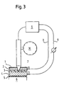
- the measuring device has a Voltage source S, one pole of which is separated by two Lines 8, 9 and two electrodes a, b to the upper one electrically conductive layer 2 and the lower electrically conductive layer 4 is connected.
- the other pole of the Voltage source S is in the form of a measuring tip Metal needle 7 connected.
- the metal needle 7 is also with connected to a transmitter M.
- the layered arrangement which is shown in the Case around a container 6 closed with a film 2 is generally structured as follows.
- the Cover film 2 consists of a metal, preferably one Aluminum foil or an aluminum tape, and is with a Paint layer 1 coated.
- the paint layer 1 would in the case of Use of heated electrodes instead of the Penetrate the metal needle 7 into the layer structure, melt, what the measurement results regarding the to be recorded would falsify layer thickness. For this reason, are suitable conventional methods not for capturing the Layer thickness of the sealing seam 3 below one, for example film coated with lacquer 2.
- the intermediate layer in the shown Embodiment in the form of the sealing seam 3 is usually made of polypropylene, between the electrically conductive cover film 2 and the lower electrically conductive layer 4, which in the example shown by the Metal, preferably aluminum foil or the band formed from which the closed container is made.
- the metal needle 7 and the electrodes a, b none Circuit closed so that no current flow can be detected can.
- the metal needle 7 in a direction perpendicular to the surface of the film 2 preferably at a defined speed and below defined force is moved, so penetrates the Tip of the metal needle 7 first of all the lacquer layer 1.
- the circuit closed the one pole of the voltage source S through line 8 to electrode a, through the upper one electrically conductive layer 2, through the metal needle 7 and finally to the other pole of the voltage source S. runs.
- a current can flow into this circuit can be detected, what is shown by the line 8 Measuring device should be indicated.
- the metal needle 7 is further defined Speed in a direction perpendicular to each Layer surfaces towards the bottom electrically conductive layer 4 pressed. As shown in Fig. 3, hits the top of the metal needle 7 after it hits the top electrically conductive layer 2 and the intermediate layer 3 has permeated the surface of the bottom electrically conductive layer 4. At this point the other Circuit closed by the one pole of the Voltage source through line 9 to electrode b, through the electrically conductive layer 4, through the metal needle 7 and finally to the other pole of the voltage source S. runs. The consequently measurable current flow in this Circuit, what through the in line 9 in Fig. 3rd indicated measuring device is to be indicated, closes the End contact of transmitter M and ends the measurement. With in other words, that between the two times, too which the first and the second circuit closed is covered by the measuring tip and covered by a display device of the transmitter M is output.
- the layer thickness of the upper electrically conductive Layer 2 including the thickness of the sealing compound in the Sealing seam 3 can be calculated. Possibly. can be in a suitable Storage device the thickness of the upper electrically conductive Layer 2 are deposited, so that without further ado the thickness of layer 3 can be determined.
- the Transmitter M gives the layer thickness to be recorded immediately.
- the probe tip 7 could be designed so that one end of the current flow through the upper layer 2 is detectable. In this case, the thickness Layer 3 can be calculated immediately.
- the structure is extremely simple schematically illustrated measuring device in the context of a simple means feasible procedure for a reliable measurement of the thickness of a layer 3 between two electrically conductive layers 2, 4.
- the measurement also by any coatings of the electrically conductive Layers 2, 4 are not affected since they are not melted, but through the pointed end of the metal needle 7 just be penetrated.
- the clamping point of the layered material so preferably the Container edge flange one sealed with a foil Container advantageously in the immediate vicinity can be arranged where the Metal needle 7 penetrates, also can not Impairment of the measurement results by an oblique Intrusion or the like occur.
- the container on its outside is coated with a further polypropylene layer 5 which in the figures at the bottom of the schematic shown layer structure of the container edge flange is recognizable.
Landscapes
- Physics & Mathematics (AREA)
- General Physics & Mathematics (AREA)
- Measurement Of Length, Angles, Or The Like Using Electric Or Magnetic Means (AREA)
Applications Claiming Priority (2)
| Application Number | Priority Date | Filing Date | Title |
|---|---|---|---|
| DE1998122739 DE19822739C1 (de) | 1998-05-20 | 1998-05-20 | Verfahren und Vorrichtung zur Messung der Dicke einer Zwischenschicht |
| DE19822739 | 1998-05-20 |
Publications (2)
| Publication Number | Publication Date |
|---|---|
| EP0959323A2 true EP0959323A2 (fr) | 1999-11-24 |
| EP0959323A3 EP0959323A3 (fr) | 2000-04-26 |
Family
ID=7868479
Family Applications (1)
| Application Number | Title | Priority Date | Filing Date |
|---|---|---|---|
| EP99108520A Withdrawn EP0959323A3 (fr) | 1998-05-20 | 1999-05-04 | Méthode et dispositif de mesure d'épaisseur d'une couche intermédiaire |
Country Status (2)
| Country | Link |
|---|---|
| EP (1) | EP0959323A3 (fr) |
| DE (1) | DE19822739C1 (fr) |
Cited By (2)
| Publication number | Priority date | Publication date | Assignee | Title |
|---|---|---|---|---|
| US9617056B2 (en) | 2006-02-03 | 2017-04-11 | Ardagh Mp Group Netherlands B.V. | Expandable container having lid for providing headspace control in a food can |
| JP2018004336A (ja) * | 2016-06-29 | 2018-01-11 | 日本電気株式会社 | 検査装置、検査方法および検査プログラム |
Families Citing this family (2)
| Publication number | Priority date | Publication date | Assignee | Title |
|---|---|---|---|---|
| DE102007026700A1 (de) * | 2007-05-31 | 2008-12-11 | Solarwatt Ag | Schichtdickenmessgerät und Verfahren zur Schichtdickenmessung für verzinnte Metallbänder als elektrische Verbinder |
| CN102288090B (zh) * | 2011-04-25 | 2013-04-24 | 青岛人民印刷有限公司 | 一种自动测厚仪及自动测厚系统 |
Family Cites Families (7)
| Publication number | Priority date | Publication date | Assignee | Title |
|---|---|---|---|---|
| US3432933A (en) * | 1966-11-14 | 1969-03-18 | Robert E Wood | Gauge for measuring the thickness of blankets on printing rollers |
| DK138407B (da) * | 1970-02-20 | 1978-08-28 | Slagteriernes Forskningsinst | Fremgangsmåde til bestemmelse af tykkelsen af spæk- og kødlag i slagtede dyrekroppe og måleapparat til udøvelse af fremgangsmåden. |
| DE3416659A1 (de) * | 1984-05-05 | 1985-11-07 | NATEC Institut für naturwissenschaftlich-technische Dienste GmbH, 2000 Hamburg | Verfahren und vorrichtung zur zerstoerungsfreien schichtdickenmessung an miteinander verschweissten oder versiegelten metall-kunststoff-verbundfolien |
| SU1397712A1 (ru) * | 1985-02-13 | 1988-06-15 | Предприятие П/Я Р-6799 | Способ измерени толщины |
| JPS61270603A (ja) * | 1985-05-24 | 1986-11-29 | Kawasaki Steel Corp | 二層構造板材の板厚比測定方法 |
| US5264876A (en) * | 1989-08-10 | 1993-11-23 | Canon Kabushiki Kaisha | Recording medium, method for preparing the same, recording and reproducing device, and recording, reproducing and erasing method by use of such recording medium |
| DE19642768C1 (de) * | 1996-10-16 | 1998-05-20 | Alcan Gmbh | Vorrichtung und Verfahren zur zerstörungsfreien Messung von Schichtdicken |
-
1998
- 1998-05-20 DE DE1998122739 patent/DE19822739C1/de not_active Expired - Fee Related
-
1999
- 1999-05-04 EP EP99108520A patent/EP0959323A3/fr not_active Withdrawn
Cited By (3)
| Publication number | Priority date | Publication date | Assignee | Title |
|---|---|---|---|---|
| US9617056B2 (en) | 2006-02-03 | 2017-04-11 | Ardagh Mp Group Netherlands B.V. | Expandable container having lid for providing headspace control in a food can |
| US10017313B2 (en) | 2006-02-03 | 2018-07-10 | Ardagh Mp Group Netherlands B.V. | Expandable container having lid for providing headspace control in a food can |
| JP2018004336A (ja) * | 2016-06-29 | 2018-01-11 | 日本電気株式会社 | 検査装置、検査方法および検査プログラム |
Also Published As
| Publication number | Publication date |
|---|---|
| EP0959323A3 (fr) | 2000-04-26 |
| DE19822739C1 (de) | 1999-11-11 |
Similar Documents
| Publication | Publication Date | Title |
|---|---|---|
| DE2431907C3 (de) | Verfahren und Vorrichtung zur Bestimmung von Konzentrationsprofilen flüssiger oder gasförmiger Stoffe längs einer Strecke | |
| DE4325878A1 (de) | Verfahren zur Bewertung von Widerstandsschweißverbindungen | |
| EP0945348B1 (fr) | Machine de formage, remplissage et scellement de sachets | |
| EP0465797B1 (fr) | Appareil pour mesurer la teneur en fer dans des couches de zinc | |
| EP0282900A2 (fr) | Procédé et dispositif de mesure du point de rosée | |
| DE19937387C1 (de) | Vorrichtung zur Überwachung eines Auftrags eines flüssigen bis pastenförmigen Mediums auf ein Substrat | |
| DE19822739C1 (de) | Verfahren und Vorrichtung zur Messung der Dicke einer Zwischenschicht | |
| EP0886775B1 (fr) | Procede et sonde a immersion pour la mesure d'une activite electrochimique | |
| DE19709609A1 (de) | Vorrichtung und Verfahren zum Messen einer Meßgröße bei einem Kunststoff-Spritzgießverfahren | |
| EP1205293A1 (fr) | Procédé pour mesurer l'épaisseur de films multicouches | |
| EP2322341B1 (fr) | Procédé de contrôle de l'état de fusion lors de la fabrication d'une couture d'une soudure de matière synthétique | |
| DE2033619B2 (de) | Meßgerät zur Bestimmung der Korrosionsgeschwindigkeit von Metallen und korrosiven Medien | |
| DE19803838C2 (de) | Verwendung eines Verfahrens zum Betreiben einer Schlauchbeutelmaschine zur Erkennung eines Produkteinschlusses | |
| DE102011050708A1 (de) | Vorrichtung zur Überprüfung der Schälfestigkeit von Siegelnähten | |
| DE2745244C2 (de) | Verfahren zur Bestimmung der Zeitabhängigkeit der Länge eines Risses in einem Probekörper bei einem Bruchversuch und Vorrichtung zur Durchführung des Verfahrens | |
| DE3416659C2 (fr) | ||
| DE4127018C2 (de) | Prüfvorrichtung für aufgeklebte Folien | |
| DE2640155C3 (de) | Nach dem Wirbelstromprinzip arbeitende Meßvorrichtung zur kontinuierlichen Messung der Dicke eines sich bewegenden, aus Metall bestehenden Meßobjekts. | |
| DE19909864B4 (de) | Verfahren und Vorrichtung zur Herstellung einer Folienbahn | |
| DE10348169B4 (de) | Vorrichtung und Verfahren zur Bestimmung des Gasdruckes in metallumhüllten Hohlkörpern | |
| DE3320971C2 (de) | Vorrichtung zum Prüfen der mechanischen Festigkeit von flexiblen Packstoffen und Packstoffverbunden | |
| DE3937205A1 (de) | Messeinrichtung zur erfassung einer physikalischen groesse | |
| DE19540232C1 (de) | Verfahren und Drucksensor zum Messen von hydrodynamischen und hydrostatischen Drücken | |
| DE10220551A1 (de) | Verfahren und Vorrichtung zur Erfassung der Materialeigenschaft und/oder der Geschwindigkeit einer sich bewegenden Materialbahn | |
| DE19620053C1 (de) | Verfahren zum zerstörungsfreien Untersuchen der Oberflächenschicht elektrisch leitfähiger Werkstücke |
Legal Events
| Date | Code | Title | Description |
|---|---|---|---|
| PUAI | Public reference made under article 153(3) epc to a published international application that has entered the european phase |
Free format text: ORIGINAL CODE: 0009012 |
|
| AK | Designated contracting states |
Kind code of ref document: A2 Designated state(s): DE FR |
|
| AX | Request for extension of the european patent |
Free format text: AL;LT;LV;MK;RO;SI |
|
| PUAL | Search report despatched |
Free format text: ORIGINAL CODE: 0009013 |
|
| RIC1 | Information provided on ipc code assigned before grant |
Free format text: 7G 01B 7/06 A, 7G 01B 5/06 B |
|
| AK | Designated contracting states |
Kind code of ref document: A3 Designated state(s): AT BE CH CY DE DK ES FI FR GB GR IE IT LI LU MC NL PT SE |
|
| AX | Request for extension of the european patent |
Free format text: AL;LT;LV;MK;RO;SI |
|
| 17P | Request for examination filed |
Effective date: 20000908 |
|
| AKX | Designation fees paid |
Free format text: DE FR |
|
| RBV | Designated contracting states (corrected) |
Designated state(s): DE GB |
|
| RAP1 | Party data changed (applicant data changed or rights of an application transferred) |
Owner name: DELTA PLUS PRAEZISIONSMESSTECHNIK GMBH & CO. KG |
|
| STAA | Information on the status of an ep patent application or granted ep patent |
Free format text: STATUS: THE APPLICATION IS DEEMED TO BE WITHDRAWN |
|
| 18D | Application deemed to be withdrawn |
Effective date: 20031202 |