EP0959347A1 - Thermisches analysegerät - Google Patents
Thermisches analysegerät Download PDFInfo
- Publication number
- EP0959347A1 EP0959347A1 EP98955927A EP98955927A EP0959347A1 EP 0959347 A1 EP0959347 A1 EP 0959347A1 EP 98955927 A EP98955927 A EP 98955927A EP 98955927 A EP98955927 A EP 98955927A EP 0959347 A1 EP0959347 A1 EP 0959347A1
- Authority
- EP
- European Patent Office
- Prior art keywords
- data
- accumulating
- measuring
- thermal analysis
- station
- Prior art date
- Legal status (The legal status is an assumption and is not a legal conclusion. Google has not performed a legal analysis and makes no representation as to the accuracy of the status listed.)
- Withdrawn
Links
- 238000010438 heat treatment Methods 0.000 claims abstract description 15
- 238000002076 thermal analysis method Methods 0.000 claims description 25
- 230000005540 biological transmission Effects 0.000 claims description 24
- 238000005259 measurement Methods 0.000 claims description 19
- 230000008859 change Effects 0.000 claims description 3
- 238000012544 monitoring process Methods 0.000 abstract description 2
- 238000000034 method Methods 0.000 description 51
- 230000008569 process Effects 0.000 description 43
- 238000004891 communication Methods 0.000 description 19
- 230000006870 function Effects 0.000 description 6
- 230000008901 benefit Effects 0.000 description 4
- 230000000694 effects Effects 0.000 description 4
- 238000012545 processing Methods 0.000 description 4
- 230000006641 stabilisation Effects 0.000 description 4
- 238000011105 stabilization Methods 0.000 description 4
- 238000009825 accumulation Methods 0.000 description 2
- 230000003247 decreasing effect Effects 0.000 description 2
- 238000005516 engineering process Methods 0.000 description 2
- 238000010009 beating Methods 0.000 description 1
- 239000000470 constituent Substances 0.000 description 1
- 230000007547 defect Effects 0.000 description 1
- 230000006872 improvement Effects 0.000 description 1
- 238000011282 treatment Methods 0.000 description 1
Images




Classifications
-
- G—PHYSICS
- G01—MEASURING; TESTING
- G01N—INVESTIGATING OR ANALYSING MATERIALS BY DETERMINING THEIR CHEMICAL OR PHYSICAL PROPERTIES
- G01N25/00—Investigating or analyzing materials by the use of thermal means
- G01N25/20—Investigating or analyzing materials by the use of thermal means by investigating the development of heat, i.e. calorimetry, e.g. by measuring specific heat, by measuring thermal conductivity
- G01N25/48—Investigating or analyzing materials by the use of thermal means by investigating the development of heat, i.e. calorimetry, e.g. by measuring specific heat, by measuring thermal conductivity on solution, sorption, or a chemical reaction not involving combustion or catalytic oxidation
- G01N25/4806—Details not adapted to a particular type of sample
- G01N25/4813—Details not adapted to a particular type of sample concerning the measuring means
Definitions
- the preset invention relates to thermal analysis apparatuses.
- thermal analysis properties to take a long time in measurement time.
- the measurement usually requires several hours and, in a long case, may take several days.
- it is not necessarily required for a user to be present close to a heating oven.
- a laboratory or the like placed with a heating oven and a sitting room or the like for usual job are distant for a safety sake or the like, it has been a practice for a user to attend in the laboratory when beginning measurement and thereafter reciprocates between the laboratory and the sitting room to see data situations. Due to this, there has been a demand to watch data during measurement from a sitting room or the like.
- a network window system such as X-Window
- X-Window a network window system
- the adoption of X-Window enables to display on and input to a thermal analysis apparatus through an X server on the network.
- the control and monitor with the thermal analysis apparatus has been enabled at a sitting room by setting up an X server within a sitting room and a thermal analysis apparatus other than the user interface within the laboratory with a network medium connected there between.
- the conventional technology includes the following problems.
- the present invention has been developed in order to solve the above problem, and has principal constituent elements of a heating oven, a temperature sensor, a physical amount sensor, a heating oven control means, a data accumulating means, a data transmission request receiving means, a data transmitting means, a measurement user interface means, a data specifying means, a data transmission request transmitting means, a data receiving means, a data display means, a monitor user interface means and a network medium.
- Structuring is made such that a measuring section and a monitor section are connected by the network medium wherein the measurement user interface is placed around the heating oven so that data at an arbitrary time point is monitored at a remote site. Accordingly, inconvenience at starting measurement is eliminated which is encountered in a case that the measurement interface is located at a remote site.
- Fig. 1 is a hardware configuration in an embodiment of the present invention.
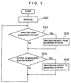
- Fig. 2 is a flowchart of principal software to be executed by a measuring module central processor and memory unit in the embodiment of the present invention.
- Fig. 3 is a flowchart of principal software to be executed by a measuring station central processor and memory unit in the embodiment of the present invention.
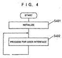
- Fig. 4 is a flowchart of principal software to be executed by a monitor station central processor and memory unit in the embodiment of the present invention.
- Fig. 5 is a flowchart of a data specifying process subroutine called from the principal software for the monitor station in the embodiment of the present invention.
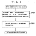
- Fig. 6 is a flowchart of a data receiving process subroutine called from the principal software for the monitor station in the embodiment of the present invention.
- Fig. 7 is an explanatory chart of a data specifying means and data transmitting means in the embodiment of the present invention.
- Fig. 8 is an explanatory chart of a data specifying means in another embodiment utilizing a broadcast function of the present invention.
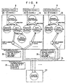
- Fig. 9 is an explanatory chart of a data specifying means in another embodiment prepared with software for accumulating the presence and absence of data of the present invention.
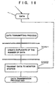
- Fig. 10 is a flowchart of a data transmitting process in another embodiment of a means to perform data transmission without preventing the data accumulating means of the present invention.
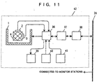
- Fig. 11 is a hardware configuration in another embodiment according to a measuring module station of the present invention.
- Fig. 1 is a hardware structure in the embodiment of the present invention.
- a measuring module 8 heats up The sample 4 according to instructions from a measuring station 16 and detects the temperature and physical amount of the sample 4, and transmits the data to the measuring station 16.
- the measuring module 8 performs its function according to software shown in Fig. 2.
- the user of the thermal analysis apparatus put a sample 4 in a heating oven 1.
- the sample 4 is detected of variation in temperature by a temperature sensor 2, and the sample 4 is detected of change in physical amount by a physical amount sensor 3.
- the physical amount sensor 3, if for example DSC, detects movement of heat quantity for the sample 4, if TG weight variation of the sample, and if TMA shape variation of the sample 4.
- the heating oven 1, the temperature sensor 2 and the physical sensor 3 are connected to a measuring module input/output interface 5, and further connected to a measuring module central processor and memory unit 6.
- the temperature control of the beating oven 1 is made by the measuring module central processor and memory unit 6 connected to the heating oven through the measuring module input/output interface 5. Also, the measuring module central processor and memory unit 6 is connected to a measuring station 16 through a measuring module communication interface 7.
- the measuring station 16 makes processing on instructions to the user interface about measurement and to a plurality of measuring modules 8, data accumulation, and data transmission request and data transmission with a monitor station 23, which uses so-called a personal computer or work station.
- the measuring station 16 performs its function by a general purpose operating system, such as Windows, Windows-NT and UNIX, and software shown in Fig. 3.
- the user of the thermal analysis apparatus effects dialogue through a measuring station mouse 11, a measuring station keyboard 15 and a measuring station CRT 10, to give instructions to the measuring module 8.
- These devices are connected to the measuring station central processor and memory unit 13 through the measuring station input/output interface 12.
- the measuring station central processor and memory unit 13 is connected to a plurality of measuring modules 8 through a measuring station communication interface 9 and a measuring module-measuring station communication path 25.
- the measuring module-measuring station communication path 25 may be any of general purpose communication paths such as RS-232-C, GP-IB and SCSI.
- the data transmission request and the data transmission to and from the monitor station 23 are made through a measuring station network interface 14 and a network medium 24 that are connected to the measuring station central processor unit 13.
- the network medium 24 may be any of general purpose network mediums, such as Ethernet, FDDI and TokenRing.
- the monitor station 23 is to specify data to be monitored and monitor the data, and uses so-called a personal computer or work station.
- the monitor station 23 effects its function through a general purpose operating system, such as Windows, Windows-NT or UNIX, and software as shown in Fig. 4, Fig. 5 and Fig. 6.
- the user of the thermal analysis apparatus specifies data to be monitored through a monitor station mouse 18, monitor station keyboard 22 and monitor station CRT 17 to monitor the data. These devices is connected to a monitor station central processor and memory unit 20 through a monitor station input/output interface 19.
- monitor station central processor and memory unit 20 is connected to a plurality of measuring stations 16 through a monitor station network interface 21 and network medium 24.
- Fig. 2 is a flowchart of software to be executed on the measuring module central processor and memory medium 6.
- initialization is made in order to prepare an operating environment [S201]. Then, If there is an input from the measuring station 16 through the measuring module communication interface 7 [S202], the input is processed [S203]. If there is an output to the measuring station 16 [S205], the output is processed [S204]. Transmission is made to the measuring station 16 via the measuring module interface 7.
- the inputs from the measuring station 16 include the followings:
- the output to the measuring station 16 includes the followings:
- Fig. 3 is software to be executed on the measuring station central processor and memory unit 13, which is executed for each measuring module 8 to be connected. That is, when there are a plurality of measuring modules 8 to be connected, the independent software as shown in Fig. 3 is being executed on the measuring station central processor and memory unit 13.
- This software performs initialization to adjust an operating environment [S301], and generate a constant time dealing process to effect constant time treatments at an appropriate interval [S302].
- the constant time dealing process performs communication with the measuring module 8 through the measuring station communication interface 9.
- the constant time dealing process if there is a content to be outputted to the measuring module 8, the content is placed in an output transaction.
- the constant time dealing process if there is an output to the measuring module 8 [S310], outputs the content of the output transaction to the measuring module 8 [S311). If there is input from the measuring module 8 [S312], the input is processed to place the content in the input transaction [S313].
- the communication with the measuring module 8 is processed by the independent process thereby preventing errors from occurring in the communication requiring real time characteristics.
- a main process generates a constant time dealing process and thereafter generates a data accumulating process [S303].
- the data accumulating process makes reference to an input transaction. If data is sent from the measuring module 8 [S320], the data is taken out of the input transaction to accumulate it in an accumulation site [S321]. Also, if there is an inquiry on the presence or absence of data from the monitor station 23 [S322], it is processed [S323]. If there is a data transmission request from the monitor station 23 [S324], it is processed [S325]. (The detail of [S322] - [S325] and [S330] - [S331] is stated later.)
- the data accumulating process is processed by the independent process whereby data pick-up errors are prevented to cope with inquiries or the like that are asynchronous with the main process from the monitor station 23.
- the main process thus generated the data accumulating process then processes for the user interface about measurement [S304].
- the instruction or setting on measurement given by the user is processed here, and an appropriate content is placed in an output transaction thereby being delivered to the measuring module 8. Also, the state of the measuring module 8 is outputted to the measuring user interface by processing the input transaction [S304].
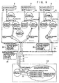
- Fig. 4 is software to be executed on the monitor station central processor and memory unit 20. This software is initialized to adjust an operating environment [S401], and processes on the user interface about monitoring [S402]. In this processing on the user interface, data to be monitored is specified and data is received.
- the user specifies on which data is to be monitored. Due to this, an instruction is made to the user interface of the monitor station 23. By processing on the user interface of the monitor station 23 [S402], a data specifying process subroutine in Fig. 5 is called out.
- the data specifying process subroutine thus called out ask for inputting a host name or a network address to the user, and receives an input [S503].
- Those connected to the network medium 24 are assigned with an network address and host name peculiar to each of the stations as shown at 26 in Fig. 7. By assigning this, determination is made as to in which measuring station 16 data is to be monitored.
- the data specifying process subroutine inquires about the presence or absence of data in each measuring module 8 connected to the specified measuring station 16 to the measuring station 16.
- the measuring station communication interface 9 is set with a channel number for each connection port.
- the network has a configuration called port numbers to discriminate a connection port for each of software, in order to share one network by a multiplicity of software. By combining a port number with a channel number, inquire is made for a data accumulating process corresponding to each measuring module 8.
- the software of the present invention uses port numbers beginning from a port number 10000 wherein a promise is previously defined that 10000 added with a channel number be a port number of a network connection port for each data accumulating process. Inquires are made up to a channel number having a possibility of connection as in [S503] - [S505] .
- the network connection port inquired, as in the path 27 of inquire on the presence and absence of data to each data accumulating process in Fig. 7, is (network address: port number) 192. 168. 0. 1 : 10001 192. 168. 0. 1 : 10002.
- Each data accumulating process inquired sends back on the presence or absence of data through [S322] - [S323].
- the data specifying process subroutine displays a channel number through which the presence of data is responded [S506] and asks the user for selecting as to which channel number of a measuring module 8 is to be monitored [S507].
- the software on the monitor station 23 calls a data receiving process subroutine following a data specifying process subroutine.
- the data receiving process subroutine sends a data transmitting request onto a network connecting port of the specified data accumulating process (192. 168. 0. 1 : 10001 in the case of a data transmission request path 20 for the specified data accumulating process in Fig. 7) [S601].
- the data transmission process creates a duplicate of data [S330]. By making a data duplicate, it can be avoided to prevent the data in the data accumulating process from accumulating without conscious that the data transmitting process keeps consistency on the accumulated data.
- the data transmitting process sends data to the monitor station 23 as through the data transmission path 29 to the specified data accumulating process in Fig. 7 [S331].
- the data receiving process subroutine receives sent data and displays the data [S602].
- data monitor is carried out at a remote site.
- the first one is on another embodiment of a data specifying means.
- Fig. 8 is an explanatory chart on another embodiment utilizing a broadcast function in the data specifying means.
- This method has an advantage that the channel numbers for all the measuring stations having data on the network can be displayed without previously specifying measuring stations 16.
- the second is on another embodiment of a data specifying means.
- Fig. 9 is an explanatory chart of another embodiment prepared with software for accumulating the presence or absence of data.
- Prepared is one software for accumulating the presence or absence of data.
- the operation site may be on any of the measuring station 16 or monitor station 23, or on a not-related computer other than those.
- the data accumulated process is previously taught of a network address at a site where software for accumulating the presence or absence of data is operating.
- the presence or absence is periodically sent to the data presence/absence accumulating software as in 32, 33 and 34 in Fig. 9. Due to this, created is a table of network connecting ports to data accumulating processes in which data exists.
- the monitor software is sent by the table of network connecting ports to data accumulating processes as in 35 in Fig. 9, thereby displaying all the channel numbers having data on the network without effecting [S501] - [S503] in Fig. 5.
- the advantage of this method lies in that all measuring station channel numbers on the network can be displayed with less communication amount on the network medium 24 and reduced time.
- the third is on anther embodiment of a data transmitting means without preventing the data accumulating means.
- Fig. 10 is an improvement over [S330] - [S331] in Fig. 3, wherein the data duplicate creation in [S330] is changed to creating a duplicate on the number of data in [S1001]. Because a data accumulating program merely makes addition to the data, the number of the data up to this time is duplicated to thereby transmit the data to the monitor station 23 without duplicating the data [S1002].
- the advantage of this method lies in that the memory unit can be saved.
- the fourth is on another embodiment utilizing a measuring module station combining the measuring module 8 with the measuring station 16.
- Fig. 11 is a hardware configuration of a measuring module station 42 having a combination of the measuring module 8 and the measuring station 16.
- the software of Fig. 2 and Fig. 3 operates on the measuring module station central processor and memory unit 37.
- the advantage of this method lies in that t is possible to reduce cost when one thermal analysis technique is employed.
Landscapes
- Chemical & Material Sciences (AREA)
- Engineering & Computer Science (AREA)
- Chemical Kinetics & Catalysis (AREA)
- Combustion & Propulsion (AREA)
- Physics & Mathematics (AREA)
- Health & Medical Sciences (AREA)
- Life Sciences & Earth Sciences (AREA)
- Analytical Chemistry (AREA)
- Biochemistry (AREA)
- General Health & Medical Sciences (AREA)
- General Physics & Mathematics (AREA)
- Immunology (AREA)
- Pathology (AREA)
- Investigating Or Analyzing Materials Using Thermal Means (AREA)
- Arrangements For Transmission Of Measured Signals (AREA)
Applications Claiming Priority (3)
| Application Number | Priority Date | Filing Date | Title |
|---|---|---|---|
| JP32502497 | 1997-11-26 | ||
| JP32502497 | 1997-11-26 | ||
| PCT/JP1998/005308 WO1999027354A1 (fr) | 1997-11-26 | 1998-11-25 | Analyseur thermique |
Publications (2)
| Publication Number | Publication Date |
|---|---|
| EP0959347A1 true EP0959347A1 (de) | 1999-11-24 |
| EP0959347A4 EP0959347A4 (de) | 2002-02-06 |
Family
ID=18172300
Family Applications (1)
| Application Number | Title | Priority Date | Filing Date |
|---|---|---|---|
| EP98955927A Withdrawn EP0959347A4 (de) | 1997-11-26 | 1998-11-25 | Thermisches analysegerät |
Country Status (3)
| Country | Link |
|---|---|
| US (1) | US6542084B1 (de) |
| EP (1) | EP0959347A4 (de) |
| WO (1) | WO1999027354A1 (de) |
Cited By (2)
| Publication number | Priority date | Publication date | Assignee | Title |
|---|---|---|---|---|
| EP1111376A3 (de) * | 1999-12-20 | 2002-03-06 | Seiko Instruments Inc. | Thermisches Analysegerät |
| US6535678B1 (en) | 1999-03-31 | 2003-03-18 | Fujikura Ltd | Multimode optical fiber with a higher order mode removing function |
Families Citing this family (2)
| Publication number | Priority date | Publication date | Assignee | Title |
|---|---|---|---|---|
| DE102020004841A1 (de) | 2020-08-07 | 2022-02-10 | Mettler-Toledo Gmbh | Verfahren und Vorrichtung zur Ermittlung einer beobachtbaren Eigenschaft eines Objekts |
| DE102020004838A1 (de) | 2020-08-07 | 2022-02-10 | Mettler-Toledo Gmbh | Verfahren und Vorrichtung zur sensorischen Messung einer Stoffprobe |
Family Cites Families (7)
| Publication number | Priority date | Publication date | Assignee | Title |
|---|---|---|---|---|
| US3637985A (en) * | 1969-01-21 | 1972-01-25 | Ball Corp | Portable remote location measuring system |
| US4982347A (en) * | 1989-06-22 | 1991-01-01 | Unisys Corporation | Process and apparatus for producing temperature profiles in a workpiece as it passes through a belt furnace |
| JP2860500B2 (ja) * | 1990-08-09 | 1999-02-24 | セイコーインスツルメンツ株式会社 | 熱分折解析装置 |
| JP3002912B2 (ja) * | 1991-07-16 | 2000-01-24 | セイコーインスツルメンツ株式会社 | 熱分析装置 |
| JP3124372B2 (ja) * | 1992-05-22 | 2001-01-15 | セイコーインスツルメンツ株式会社 | 熱分析装置 |
| US5416727A (en) * | 1992-12-15 | 1995-05-16 | American Ceramic Service Company | Mobile process monitor system for kilns |
| US5582235A (en) * | 1994-08-11 | 1996-12-10 | Micro Control Company | Temperature regulator for burn-in board components |
-
1998
- 1998-11-25 US US09/355,226 patent/US6542084B1/en not_active Expired - Fee Related
- 1998-11-25 WO PCT/JP1998/005308 patent/WO1999027354A1/ja not_active Ceased
- 1998-11-25 EP EP98955927A patent/EP0959347A4/de not_active Withdrawn
Cited By (3)
| Publication number | Priority date | Publication date | Assignee | Title |
|---|---|---|---|---|
| US6535678B1 (en) | 1999-03-31 | 2003-03-18 | Fujikura Ltd | Multimode optical fiber with a higher order mode removing function |
| EP1111376A3 (de) * | 1999-12-20 | 2002-03-06 | Seiko Instruments Inc. | Thermisches Analysegerät |
| US6529848B2 (en) | 1999-12-20 | 2003-03-04 | Seiko Instruments Inc. | Thermal analysis apparatus |
Also Published As
| Publication number | Publication date |
|---|---|
| EP0959347A4 (de) | 2002-02-06 |
| WO1999027354A1 (fr) | 1999-06-03 |
| US6542084B1 (en) | 2003-04-01 |
Similar Documents
| Publication | Publication Date | Title |
|---|---|---|
| US5726912A (en) | Control system monitor | |
| JP4235300B2 (ja) | 通信システム | |
| US5568402A (en) | Communication server for communicating with a remote device | |
| JP2007528053A (ja) | 無線及び配線ベースの経路を使った製造プラント内のフィールド装置の遠隔管理 | |
| JPH09138777A (ja) | ネットワークシステム | |
| EP0959347A1 (de) | Thermisches analysegerät | |
| US20050134911A1 (en) | Image processing system, method of controlling the image processing system, and program for a peripheral apparatus in the system | |
| KR101299451B1 (ko) | 스캐닝 장치, 네트워크 스캐닝 시스템 및 스캐닝 장치의 네트워크 스캔 방법 | |
| JP2000215244A5 (de) | ||
| JPH0546631A (ja) | 製造ライン | |
| JP3668799B2 (ja) | 検体検査システム | |
| JP3662492B2 (ja) | 遠隔操作システム、その装置及び記録媒体 | |
| JPWO1999027354A1 (ja) | 熱分析装置 | |
| CN115102876A (zh) | 电故障诊断方法、装置、设备与介质 | |
| JP4387487B2 (ja) | 情報処理装置、ネットワークシステム、情報処理方法または記録媒体 | |
| JP4192253B2 (ja) | Cpdlc/aidc共用管制卓及び同ヒューマン・インタフェース | |
| JP2002064648A (ja) | 無線通信システム及び無線通信方法 | |
| JPH0488453A (ja) | 分散処理形態プログラム回線評価方式 | |
| EP1318455A2 (de) | Remotestützsystem | |
| RU2695539C1 (ru) | Способ функционирования системы испытаний земных станций спутниковой связи | |
| JPH08335149A (ja) | 情報処理装置並びに印刷装置並びに印刷システムおよび印刷システムの印刷データ転送方法 | |
| JP2970837B2 (ja) | ネットワーク図管理システム | |
| JP2024137399A (ja) | 印字検査装置のリモート制御サポートシステムおよびその制御方法 | |
| JP2005100156A (ja) | データ処理装置、印刷デバイス、画像処理システムおよび印刷ジョブの処理方法 | |
| EP1069505A1 (de) | Remotestützsystem |
Legal Events
| Date | Code | Title | Description |
|---|---|---|---|
| PUAI | Public reference made under article 153(3) epc to a published international application that has entered the european phase |
Free format text: ORIGINAL CODE: 0009012 |
|
| 17P | Request for examination filed |
Effective date: 19990721 |
|
| AK | Designated contracting states |
Kind code of ref document: A1 Designated state(s): BE DE FR GB IT NL |
|
| RIN1 | Information on inventor provided before grant (corrected) |
Inventor name: NAKATANI, RINTARO |
|
| A4 | Supplementary search report drawn up and despatched |
Effective date: 20011220 |
|
| AK | Designated contracting states |
Kind code of ref document: A4 Designated state(s): BE DE FR GB IT NL |
|
| RIC1 | Information provided on ipc code assigned before grant |
Free format text: 7G 01N 25/00 A, 7H 04L 29/06 B |
|
| 17Q | First examination report despatched |
Effective date: 20021205 |
|
| STAA | Information on the status of an ep patent application or granted ep patent |
Free format text: STATUS: THE APPLICATION HAS BEEN WITHDRAWN |
|
| 18W | Application withdrawn |
Effective date: 20040624 |