EP0959426B9 - Verfahren zur Wiederherstellung aufeinanderfolgender Abtastungen eines Strichcodes - Google Patents
Verfahren zur Wiederherstellung aufeinanderfolgender Abtastungen eines Strichcodes Download PDFInfo
- Publication number
- EP0959426B9 EP0959426B9 EP98830306A EP98830306A EP0959426B9 EP 0959426 B9 EP0959426 B9 EP 0959426B9 EP 98830306 A EP98830306 A EP 98830306A EP 98830306 A EP98830306 A EP 98830306A EP 0959426 B9 EP0959426 B9 EP 0959426B9
- Authority
- EP
- European Patent Office
- Prior art keywords
- elements
- scan
- block
- steps
- cluster
- Prior art date
- Legal status (The legal status is an assumption and is not a legal conclusion. Google has not performed a legal analysis and makes no representation as to the accuracy of the status listed.)
- Expired - Lifetime
Links
Images


Classifications
-
- G—PHYSICS
- G06—COMPUTING OR CALCULATING; COUNTING
- G06K—GRAPHICAL DATA READING; PRESENTATION OF DATA; RECORD CARRIERS; HANDLING RECORD CARRIERS
- G06K7/00—Methods or arrangements for sensing record carriers, e.g. for reading patterns
- G06K7/10—Methods or arrangements for sensing record carriers, e.g. for reading patterns by electromagnetic radiation, e.g. optical sensing; by corpuscular radiation
- G06K7/14—Methods or arrangements for sensing record carriers, e.g. for reading patterns by electromagnetic radiation, e.g. optical sensing; by corpuscular radiation using light without selection of wavelength, e.g. sensing reflected white light
- G06K7/1404—Methods for optical code recognition
- G06K7/146—Methods for optical code recognition the method including quality enhancement steps
- G06K7/1491—Methods for optical code recognition the method including quality enhancement steps the method including a reconstruction step, e.g. stitching two pieces of bar code together to derive the full bar code
-
- G—PHYSICS
- G06—COMPUTING OR CALCULATING; COUNTING
- G06K—GRAPHICAL DATA READING; PRESENTATION OF DATA; RECORD CARRIERS; HANDLING RECORD CARRIERS
- G06K7/00—Methods or arrangements for sensing record carriers, e.g. for reading patterns
- G06K7/10—Methods or arrangements for sensing record carriers, e.g. for reading patterns by electromagnetic radiation, e.g. optical sensing; by corpuscular radiation
- G06K7/14—Methods or arrangements for sensing record carriers, e.g. for reading patterns by electromagnetic radiation, e.g. optical sensing; by corpuscular radiation using light without selection of wavelength, e.g. sensing reflected white light
- G06K7/1404—Methods for optical code recognition
- G06K7/146—Methods for optical code recognition the method including quality enhancement steps
- G06K7/1465—Methods for optical code recognition the method including quality enhancement steps using several successive scans of the optical code
Definitions
- the invention relates to a method of reconstructing successive scans of a bar code.
- bar codes are optical codes containing coded information made up of a plurality of rectangular elements (bars) having a dark colour (normally black) separated by light elements (spaces, normally white).
- Reading devices for the said bar codes usually comprise an illumination device (e.g. a laser beam source) adapted to send an optical reading beam which moves along a scanning path intersecting the bar code and also comprise a sensor (e.g. a photodiode) which receives part of the diffused light from the portion of the scanning path illuminated by the laser spot.
- the sensor in response to the radiation falling on it as a result of scanning a bar code, outputs an alternating electric signal having a wave shape which is modulated by the succession of light and dark elements in the bar code.
- a signal generated by scanning the bar code is successively binarised and has a two-level wave shape which represents the elements of the bar code and comprises a first high level when scanning a space and a second low level when scanning a bar.
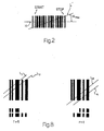
- Normally bar codes are examined in a scanning direction which does not coincide with the longitudinal axis of the code.
- the scanning direction is therefore usually at an angle to the longitudinal axis of the bar code. More particularly, when this angle exceeds a threshold value ⁇ max (Fig. 2), a subset of the code elements are scanned and the binarised signal, which relates to a partial scan of the bar code, comprises a subset of the code elements.
- Some known reconstruction devices are adapted to put together successive partial scans of the same code, made in different positions, in order to reconstruct and decode the bar code.
- Reconstruction devices of this kind which put together those elements of a partial scan which have a given inclination with respect to the longitudinal axis of the bar code, effect an omnidirectional readout of the code.
- EP 0 436 072 discloses i.a. a method for decoding bar code symbols in which a bar code reader and associated components using timing information associated with the flying spot beam as it scans a bar code symbol having a succession of linear elements of different light reflectivity, produce a representation of the symbol and attempt to decode the representation of the symbol in order to produce a legitimate character message containing legitimate characters which are decodable.
- a first and a second representation of the bar code symbol are stored corresponding to a first and a second scan path through a first and a second portion of said symbol along with timing information representing the elapsed time between a first and a second reference time and the moment at which a predetermined bar or space of a predetermined character was crossed by the spot.
- the timing information is utilized in conjunction with the stored information to reconstitute the complete symbol. More in particular, a predicted time from the next start-of-scan change to the start of a character is calculated and used as a reference time to locate and decode the stored representation of a character in the next scan, where the character is the last successfully decoded character of the previous scan.
- the method implements a reconstruction of the code character by character instead of element by element.
- the position of the characters of the bar code is referred to the beginning of the relevant scan. Also, one character of the code is chosen and its expected start position in a subsequent scan is calculated so that the character chosen is looked for, using a decoding algorithm, in the subsequent scan. No comparison of the elements of the two scans is carried out.
- US 5,387,787 discloses a method for reading machine readable code, comprising the steps of:
- US 5,387,787 discloses a method of reconstructing successive scans of a bar code comprising a plurality of elements, each of said elements having a first or a second reflectivity and being represented by a width and a position with respect to a reference position, comprising the steps of:
- the position identification data of the elements of the bar code is not referred to an absolute reference position. Also, in said alignment step, one single element of the code is chosen from said first scan and its expected position in the second scan is calculated based on the shift amount so that the single chosen element is looked for in the second scan to align the two scans based on it. The elements of the two scans are then compared, in said correspondence search step, only as far as their width is concerned.
- Bar code reconstruction according to the prior art suffers therefore from inaccuracies due to the lack of taking due account of the position of the elements of the code.
- the object of the invention is to provide a method of reconstructing successive partial scans of a bar code, featuring a particularly efficient omnidirectional reading of the code. Furthermore, object of the invention is to provide a method of reconstructing successive partial scans so as to efficiently manipulate the successive partial scans.
- reference number 1 indicates as a whole a bar code reading device comprising a reading head 5 facing a conveyor belt 6 and adapted to pick out objects 7 (e.g. packets) disposed on the belt 6 and movable in a rectilinear direction D at a constant speed with respect to the reading head 5.
- objects 7 e.g. packets
- One surface 7a of each object 7 facing the reading head 5 bears one or more optical codes 8, more particularly bar codes of known kind (Fig. 2).
- Each bar code is made up of a plurality of rectangular portions (bars) having varying reflectivity, more particularly dark (normally black) portions separated by light portions (spaces, normally white). Different dark and light portions (bars and spaces) can have different widths.
- a code "element” will mean a bar or a space of the code.
- Adjacent elements of the code together form a character of the code, to which coded information is associated.
- the bar code near a first end portion thereof, has a plurality of elements which together define a code starting character, hereinafter called a START pattern (Fig. 2). Furthermore, the bar code, near a second end portion thereof, has a plurality of elements which together define an end-of-code character, hereinafter called a STOP pattern.
- the beginning-of-code and end-of-code characters i.e. the START pattern and the STOP pattern, define the so-called "synchronism characters" of the code.
- the reading head 5 comprises a known illumination device 17 (e.g. comprising a laser source 17a and a rotating prismatic mirror 17b adapted to reflect the laser beam produced by the source 17a), for directing a laser scanning beam F on to the optical codes 8 and scanning the codes 8.
- a known illumination device 17 e.g. comprising a laser source 17a and a rotating prismatic mirror 17b adapted to reflect the laser beam produced by the source 17a
- the laser beam F moves in a substantially inclined plane and intersects the belt 6 and the objects thereon along a scanning path L on which the laser spot moves from a beginning-of-scanning position Li to an end-of-scanning position Lf.
- the reading head 5 also comprises a sensor 20 (e.g. a photodiode) associated with an optical acquisition and focusing system 21 (diagrammatically represented) for picking up the diffused light radiation R in order to generate an output analog signal S(t) having an intensity proportional to the brightness of the portion of the path L which is being scanned at that moment.
- the analog signal S(t) is fed to an electronic unit 22 which processes the analog signal S(t) according to the invention.
- the unit 22 is also adapted to pick up the coded information associated with the code.
- the reading device described with reference to Fig. 1 is one example of the various reading devices which could be used in association with the method according to the invention; the device 1 could be of a different kind and could e.g. comprise a lamp or LEDs for illuminating the bar codes, or a telecamera or a CCD for picking up a grey-level bidimensional image of the bar codes and of the successive processing devices, which likewise output a signal S(t) having an intensity proportional to the brightness of a portion of a scanned bar code.
- Fig. 3a is a general block diagram of the operating cycle of an electronic processing unit 22.
- Fig. 3a proceeds from a starting block (START) to a block 100 which acquires the analog signal S(t) generated by the sensor 20 after a complete scan of scanning path L.
- a "complete scan” means a scan in which the laser spot moves from the beginning-of-scanning position Li to the end-of-scanning position Lf.
- the analog signal S(t) typically has an initial portion corresponding to scanning the beginning-of-scanning position Li (Fig. 1), a final portion corresponding to scanning the end-of-scanning position Lf and an intermediate section which, corresponding to a scanned bar code, comprises an alternating section (shown in Fig. 4a) formed by a sequence of zones P having a high amplitude (peaks) separated by zones V of low amplitude (valleys).
- a peak P represents a space whereas a valley V represents a bar.
- the analog signal S(t) is then binarised in the block 100 and, corresponding to an alternating section thereof, outputs a signal Sd(t) having two levels (shown in Fig. 4b) comprising a first high level HI on scanning a space and a second low level LO on scanning a bar.
- the high levels HI and low levels LO of the signal Sd(t) are joined by substantially vertical transition fronts which separate the different-level portions of the signal Sd(t) and represent the separation zone between two different elements (bar-space) of the code.
- the wave form of the binarised signal Sd(t) is situated on a time axis having its origin (time to) at the instant when scanning begins, i.e. the instant at which the laser spot illuminates the beginning-of-scanning position Li.
- the beginning-of-scanning position Li is an absolute spatial reference to which the positions of the bar code elements are referred and consequently the instant to is taken as an absolute time reference with respect to which the positions in time of the code elements represented by the signal Sd(t) are measured.
- time Tp measured between the time origin to and an instant ti when a digitised signal front Sd(t) is present represents the time distance between the bar code element following the considered front and the absolute reference (to).
- the time interval Tp represents the position of a bar code element with respect to the beginning-of-scanning position.
- the time width Tc of the high-level portion HI and/or low-level portion LO of the digitised signal Sd(t) represents the width of a bar code element.
- each bar code element is represented in the signal Sd(t) by a time interval Tp which represents the position of the bar code element with respect to the absolute reference (time to equivalent to the beginning-of-scanning position Li) and by a time interval Tc which represents the width of the code element.
- FRAME will mean a set of code elements as represented by the digitised signal Sd(t).
- each FRAME comprises a plurality of positions and widths representing the elements of the scanned bar code.
- a FRAME for example, can be represented by a table TABF (Fig. 9) in which:
- each CLUSTER means a storage area in which the FRAMES relating to a given bar code are stored, in the same order as the FRAMES themselves are acquired during successive scans as explained hereinafter.
- the CLUSTER elements are represented e.g. by a table TABC (Fig. 9) in which:
- Tables TABC and TABF can be scanned by respective pointers i and j which are able to select pairs of cells (one from the first row and another from the second row) which define a bar code element through its position and its width.
- the signal Sd(t) comprises a set of distinct different FRAMES F1, F2, ... Fn.
- a FRAME contains all the elements of a bar code only when the scan occurs along a line between the longitudinal axis H of the code and a line L' (Fig. 2) having an inclination equal to amax with respect to the axis H.
- the objects 7 and the optical codes 8 thereon have an arbitrary relative arrangement with respect to the scanning path L. Consequently the scanning line normally intersects only a part of the bar code.
- each FRAME normally relates to scanning of a subgroup of the bar code elements (not of the entire bar code). Consequently each FRAME relates to a partial scan and represents the cited subgroup of elements.
- successive partial scans L1, L2, ... intersect adjacent portions of the code and produce successive FRAMES which relate to different subgroups of elements.
- the invention relates to a method of reconstructing successive partial scans of bar codes starting from a general signal representing the code elements. It does not matter how the signal was generated or processed.
- the successive FRAMES relating to scanning of the same code are grouped in a respective CLUSTER which can be individually selected on the basis of the value taken by a pointer i.
- Each CLUSTER is also marked by a first index called STATUS, which indicates the state of the CLUSTER; more particularly the index can take three values corresponding to three different situations:
- STATUS 1 and STATUS 2 will be called active states, whereas STATUS 0 will be called inactive state.
- STATUS index of all the CLUSTERS will be zero.
- STATUS index of the CLUSTERS is modified (transferred to one of the two active states or set at zero) depending on the result of checks made on the CLUSTER itself or on the result of attempts to couple each CLUSTER to the extracted FRAMES as described in detail. Consequently, active CLUSTERS and inactive CLUSTERS will generally be present at every moment.
- Each CLUSTER is also marked by a second index called NOMATCH which represents the number of failed attempts made to associate additional FRAMES to the same CLUSTER.
- the block 110 is followed by a block 120 which selects the i th CLUSTER and checks the status of the first STATUS index associated with this i th CLUSTER. More particularly the block 120 checks whether the STATUS index of the i th CLUSTER is an active state, i.e.:
- a block 130 is selected; otherwise (i th CLUSTER inactive) the block 120 is followed by a block 140.
- the block 130 re-selects the i th CLUSTER and checks the value of the second NOMATCH index; more particularly if the NOMATCH index is equal to or above a threshold value MAX-NOMATCH, i.e. if at least MAX-NOMATCH failed attempts have been made to associate the i th CLUSTER with additional FRAMES, block 130 will select a block 150 for forcing to zero the first STATUS index of the i th CLUSTER which at present is active, i.e.:
- active CLUSTERS for which at least MAX-NOMATCH failed attempts have been made to associate them with new FRAMES are transferred to the inactive state, i.e. cancelled and made available for storing FRAME elements which cannot be associated with active CLUSTERS.
- the block 150 is followed by block 140.
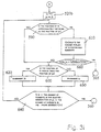
- the block 170 is adapted in known manner to select a single FRAME Fi from the signal Sd(t) relating to a complete scan.
- the block 170 is followed by a block 180 adapted to count the number Nf of elements of the FRAME Fi previously selected, i.e. the number of bar code elements represented by the FRAME. If the number Nf is above a minimum number of elements defining a threshold value, the block 180 is followed by a block 190, otherwise the block 180 is followed by a block 200.
- the block 190 (described in detail hereinafter) selected when the FRAME Fi comprises a number of elements above the minimum number of elements is adapted to process the FRAME, i.e. is adapted to try to associate the FRAME Fi with each active CLUSTER.
- the block 190 is in any case followed by the block 200, which checks whether the FRAME Fi under examination is the last FRAME contained in the scan detected by the block 100. If not, a return is made from block 200 to block 170 in order to select another FRAME Fi + 1, or otherwise (after examination of the FRAMES in the scan) a return, is made from block 200 to block 100 in order to acquire another scan. In the other scan, of course, the objects 7 will be in a different position from the preceding scan and consequently different portions of the bar code will be scanned and FRAMES will be detected relating to partial scans of the codes made in different successive positions from the positions in the preceding scan.
- Fig. 3b gives a detailed view of the block 190 adapted to process the FRAME Fi extracted from the block 170. The process consists in attempting to associate the FRAME Fi with all the active CLUSTERS present in the memory.
- the block 190 comprises a block 192 adapted to select a first CLUSTER.
- the block 192 is followed by a block 193 which checks whether the selected CLUSTER is an active CLUSTER; if so (the selected CLUSTER is active) the block 193 is followed by a block 195, otherwise (the selected CLUSTER is inactive) a block 191 is selected, which checks whether the selected CLUSTER is the last CLUSTER present in the memory. If not so (other CLUSTERS are present in the memory) the block 191 returns to block 192, otherwise (after examination of the CLUSTERS present in the memory) the block 191 selects a block 194.
- the block 195 (described in detail hereinafter) checks whether the FRAME Fi and the selected CLUSTER intersect, i.e. whether the FRAME and the CLUSTER comprise elements which have comparable positions when superposed.
- block 195 If the check of the block 195 gives a negative result (the FRAME Fi and the CLUSTER do not intersect) a return is made from block 195 to block 191. Otherwise (the FRAME Fi and the CLUSTER intersect and can be combined) the block 195 is followed by a block 196.
- the block 196 modifies a state index of the FRAME, by putting it in a state indicating the use made of the FRAME. Indeed this use is made subsequently during the next attempt to combine the FRAME Fi with the various active CLUSTERS.
- the block 196 is followed by a block 197 which checks whether the FRAME Fi has already been decoded; if not (no attempt has yet been made to decode the FRAME) the block 197 is followed by a block 197a which attempts this decoding. Otherwise (the FRAME has already been decoded) the block 197 is followed by a block 198.
- the fact that the FRAME has been successfully decoded in block 197a means that this FRAME comprises all the elements of the bar code; in that case it is of course unnecessary to reconstruct the successive partial scans. The decoded code is therefore transmitted to the exterior of the unit 22.
- the block 198 (described in detail hereinafter) tries to combine the FRAME Fi with a first active CLUSTER; if the attempt has a negative result, the contents of a counter measuring the NOMATCH number of failed combination attempts made by the CLUSTER is incremented by one unit and the block 198 is followed by the block 191 and, if this was not the last cluster, by the block 192 for selecting another active CLUSTER and repeating the effort to combine the same FRAME Fi with the additional CLUSTER.
- the block 198 is followed by a block 198a which tries to decode the CLUSTER to which the FRAME Fi has been successfully added. If the CLUSTER is successfully decoded, the decoded code is transmitted to the exterior of the unit 22.
- the block 198a is likewise followed by the block 191.
- the block 194 checks the value of the state index of the FRAME Fi indicative of its use. If the index indicates that the FRAME Fi has been subjected to a combination attempt with at least one active CLUSTER, a transition is made from block 194 to block 200 (Fig. 3a) for selecting (block 170) an additional FRAME Fi + 1 which will be subjected to the operations in block 190 described with reference to Fig. 3b. If the state index of the FRAME indicates that the FRAME Fi has not yet been subjected to a combination attempt, the block 194 is followed by a block 194a (described in detail hereinafter) which initialises a CLUSTER by inserting the FRAME Fi into it. The block 194a is likewise followed by the block 200.
- Fig. 3c shows details of the block 195 which checks whether the FRAME Fi and the selected CLUSTER intersect and are therefore superposable.
- the block 195 comprises a first block 195a which checks whether the position Tfl (Fig. 7) of the last element in the FRAME with respect to the absolute reference (the beginning-of-scanning position corresponding to the time to) is lower than the position TCf of the first element of the CLUSTER with respect to the absolute reference, i.e. Tfl ⁇ TCf (1).
- the block 195b checks whether the position TFf of the first element in the FRAME with respect to the absolute reference is higher than the position TCl of the last element in the CLUSTER with respect to the absolute reference, i.e.: TCl ⁇ TFf (2).
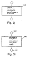
- Fig. 3d illustrates the blocks 197a or 198a, which try to decode the FRAME (or the CLUSTER).
- the block 197a, 198a comprises an initial block 201 which checks whether the length of the FRAME (or the CLUSTER) is acceptable for a bar code, i.e. whether it contains a number of elements compatible with a bar code.
- the block 201 is followed by the block 198 (or 191), otherwise the block 201 is followed by a block 202.
- the block 202 tries to decode the FRAME (or the CLUSTER) in a manner known per se, e.g. as described in US-A-3 723 710, US-A-3 761 685 or US-A-3 838 251. Decoding the frame in block 202 is sufficient in those fortunate cases where the entire code is read from the first scans. In such cases it is impossible to couple the FRAME to the relevant CLUSTER a second time (as explained in detail hereinafter with reference to block 400 in Fig.
- the block 202 is followed by the block 198 (or 191), or otherwise (the FRAME or CLUSTER is decoded successfully) the block 202 is followed by a block 203.
- the block 203 transmits the contents of decoding the FRAME (or CLUSTER) to the exterior of the unit 22, thus decoding the bar code.
- the block 203 is followed by a block 204 which indicates that the FRAME (or CLUSTER) has been decoded.
- the block 204 is followed by block 198 (or 191).
- Block 194a which initialises a CLUSTER.
- Block 194a comprises an initial block 206 for checking whether there is a synchronism character in the FRAME under examination. If the check by block 206 is positive, a transition is made to a block 207, otherwise the block 206 is followed by block 200.
- the block 207 copies all the elements of the FRAME inside a CLUSTER by transferring the position and width of all the FRAME elements to the CLUSTER.
- the block 208 is followed by the block 200.
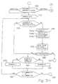
- Fig. 3f gives a detailed view of the block 198 which tries to associate a FRAME Fi with an active CLUSTER.
- the block 198 comprises an initial block 300 which controls the state index, variable between 1 and 2, of the CLUSTER.
- the CLUSTERS examined by block 300 are only active CLUSTERS, i.e. undoubtedly contain at least one FRAME in which a synchronism character is present.
- the block 300 selects a block 310 if a STATUS of 1 is detected, or a block 320 if a STATUS of 2 is detected.
- the block 310 is selected on examination of a CLUSTER which contains a single FRAME in which a synchronism character is present.
- the block 310 checks whether the FRAME under examination contains a second synchronism character. If the check is negative, the block 310 is followed by a block 330 which cancels the CLUSTER by setting its state at zero, i.e. the CLUSTER is made inactive and the possible reconstruction is blocked. The block 330 is also followed by the block 191.
- reconstruction begins. Therefore, reconstruction begins only after detection of two successive FRAMES each containing a synchronism character.
- block 310 is followed by a block 340 (described in detail hereinafter) which checks for correspondence between the FRAME and the CLUSTER in order to check whether the FRAME and the CLUSTER belong to the same code.
- a block 340 (described in detail hereinafter) which checks for correspondence between the FRAME and the CLUSTER in order to check whether the FRAME and the CLUSTER belong to the same code.
- the block 340 selects a block 345 if the check gives a negative result (FRAME and CLUSTER not aligned) or a block 350 if the check is positive (FRAME and CLUSTER in line), thus setting the STATUS of the CLUSTER at 2.
- the block 345 increases the counter defining the NOMATCH number by one unit; this block is in fact selected after a failed attempt when searching for correspondence between a FRAME and a CLUSTER.
- the block 345 is then followed by the block 191.
- the block 340 then calculates the distance between the synchronism character of the FRAME and the corresponding synchronism character of the CLUSTER.
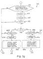
- FIG. 3g illustrates the block 340 which calculates the distance ⁇ -position after successfully checking for correspondence between the FRAME and the CLUSTER, in order to check whether the FRAME and the CLUSTER relate to scanning of the same code.
- the block 340 comprises an initial block 400 which checks whether the number of elements in the FRAME is greater than the number of elements in the CLUSTER. If this is not so, an error situation is detected and the block 400 is followed by block 345 and 191; otherwise the block 400 is followed by block 410.
- the check made in block 400 will prevent coupling between the actual FRAME and the CLUSTER and the situation will be as described hereinbefore with reference to block 197a in Fig. 3b.
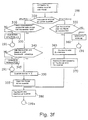
- the block 410 calculates the number f of code elements which are superposed in the FRAME and in the CLUSTER, i.e. which have the same position with respect to the absolute reference and the same width, by making the comparison (Fig. 8) starting from the first element of the FRAME and from the first element of the CLUSTER (corresponding to the left or FORWARD).
- the block 410 is followed by a block 420 which calculates the number r of elements which are superposed in the FRAME and in the CLUSTER, i.e. which have the same position with respect to the absolute reference and the same width, starting the comparison from the last element of the FRAME and from the last element of the CLUSTER (corresponding to the right or REVERSE).
- the CLUSTER contains the code elements detected in the scan marked L1
- the FRAME contains the code elements found by the scan marked L2.
- the block 420 is followed by a block 430 which checks whether the number r is equal to the number f. If the numbers r and f are equal, an uncertainty situation is detected (the number of superposable elements on the right corresponds to the number of superposable elements on the left) and consequently the code is not reconstructed.
- the block 430 is followed by blocks 345 and 191. If the numbers r and f are different, the block 430 is followed by a block 450 which checks whether the number f is greater than the number r. If the number f is greater than the number r a block 460f is selected, otherwise (f is less than r) a block 460r is selected.
- the block 460f checks whether the number f of superposable elements starting from the left is greater than a threshold value MINMATCH; if f is less than the threshold (i.e. when there are a limited number of elements which are superposed in the FRAME and in the CLUSTER), an error is detected, reconstruction does not begin and consequently blocks 345 and 191 are selected. If f is greater than the MINMATCH threshold (i.e. if there are a sufficient number of superposed elements in the FRAME and in the CLUSTER) the block 460f selects a block 470f which stores the superposition condition starting from the left (or FORWARD direction) of the bar code with respect to the reading head. The block 470f is followed by a block 480f which calculates the value ⁇ -position as the difference between the position of the first element in the FRAME and the position of the first element in the CLUSTER (see Fig. 7).
- the block 460r checks whether the number r of superposable elements starting from the right is greater than a threshold value MINMATCH. If r is less than the threshold (i.e. if there are a limited number of corresponding elements in the FRAME and in the CLUSTER) an error is detected, reconstruction does not begin and the blocks 345 and 191 are selected. If r is above the MINMATCH threshold (i.e. when there is a sufficient number of superposed elements in the FRAME and in the CLUSTER) the block 460r selects a block 470r which stores the superposition condition starting from the right (BACKWARDS or REVERSE direction) of the bar code with respect to the reading head. The block 470r is followed by a block 480r which calculates the value ⁇ -position as the difference between the position of the last element in the FRAME and the position of the last element in the CLUSTER.
- the block 350 which, as already stated, sets the first STATUS index of the CLUSTER at 2 indicating the beginning of reconstruction, is followed by a block 355 which associates the FRAME with the CLUSTER by copying the FRAME elements in the CLUSTER.
- the block 355 is followed by a block 380 which recalculates the position of the CLUSTER by disposing it in the position provided for the subsequent scan (due to the movement of the conveyor belt 6 (Fig. 1) and based on the measured displacement of the CLUSTER with respect to the just-associated FRAME.
- the belt 6 moves at a substantially constant speed (e.g. 3 metres per second) with respect to the reading head; the mirror 17b also rotates at high speed, e.g. sufficient for 1000 scans per second.
- the time between one scan and the next is very short, equal to 1/1000 of a second in the present case.
- the speed of the belt is practically constant, in that substantial variations in speed would require very high acceleration (of the order of several tens of g) which are obviously unobtainable or unimaginable in the case of a conveyor-belt device.
- the block 380 is then followed by the block 198a.
- the CLUSTER taking part in the operations of block 320 is a CLUSTER which contains two FRAMES each comprising a synchronism character; the block 320 is normally selected during the third or fourth scan of the bar code.
- block 320 If the association attempted by block 320 is unsuccessful, block 320 is followed by a block 360 which increases by one unit the counter which defines the number NOMATCH; the block 360 is then followed by the block 191.
- block 320 If the association attempt by block 320 is successful, the block 320 is followed by a block 365 (described in detail. hereinafter) which corrects the calculation of the distance ⁇ -position between the FRAME and the CLUSTER previously calculated in block 340 (Fig. 3g).
- Block 365 is followed by a block 370 (similar to block 355) which, after the operations performed by block 320, associates the new FRAME elements in the CLUSTER.
- the operations of block 370 will be described in detail hereinafter.
- Blocks 355 and 370 are followed by block 380, which in turn is followed by block 198a.
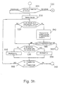
- Figs. 3h and 3i illustrate details of the block 320, which tries to associate the FRAME Fi with the CLUSTER under examination.
- the block 320 comprises an initial block 500 (Fig. 3h) which checks whether the bar code has made a FORWARD movement (block 470f, Fig. 3g) or a REVERSE movement (block 470r, Fig. 3g) with respect to the reading head.
- a block 510 is selected and in the second case (REVERSE movement) a block 520b is selected (Fig. 3i).
- Block 510 selects the last-but-one element in the CLUSTER, defined by the value ic of a pointer in Table TABC and the last-but-one element of the FRAME, defined by the value jn of a pointer in Table TABF (Fig. 9).
- the term "element ic in the CLUSTER” is used to identify the element in the CLUSTER which is defined by the pointer value ic and "element jn in the FRAME" is used to identify the element of the FRAME which is defined by the pointer value jn.
- the block 510 is followed by a block 520 which checks whether the position of element ic of the CLUSTER with respect to the absolute reference is approximately equal to the position of the element jn of the FRAME with respect to the same absolute reference.
- the block 520 is followed by the block 530. Otherwise (the positions of ic and jn substantially coincide) the block 520 is followed by a block 540.
- the block 530 checks whether the position of element ic in the CLUSTER is higher than the position of element jn in the FRAME.
- a block 555 is selected; otherwise a block 550 is selected.
- Fig. 9 illustrates the case regarding selection of the block 550 when the position of element jn of the FRAME is higher than the position of element ic of the CLUSTER.
- the block 555 decrements by unity the value of ic, i.e. performs the operation ic - 1, in order to select a CLUSTER element having a lower position than the preceding one.
- Blocks 555 and 550 are both followed by a block 560 which checks whether the values ic and jn (previously modified by the respective blocks 555 and 550) are now below a threshold value MINMATCH, i.e.: ic ⁇ MINMATCH or jn ⁇ MINMATCH
- block 560 is followed by block 360 (Figs. 3h and 3f) which detects an error situation and increases the number NOMATCH which describes the number of failed attempts at coupling between CLUSTERS and FRAMES.
- block 560 If neither inequality of block 560 is satisfied, a return is made from block 560 to block 520, which re-checks the position of the elements ic of the CLUSTER and jn of the FRAME; the check is made by a different element of the CLUSTER or FRAME from the element used in the preceding check step.
- the block 540 is selected when the elements ic and jn of the CLUSTER and of the FRAME have substantially the same position. In the example in Fig. 9 this happens when the pointer jn moves from the position from the right to the position on the left at which jn corresponds to an element (a space in the illustrated example) in the FRAME having the same position with respect to the absolute reference as the element (space) in the CLUSTER marked by ic.
- Block 540 performs the following operations:
- Block 540 is followed by a block 580 which checks whether the number A(ic, jn) is greater than the number MINMATCH, i.e.: A(ic,jn) > MINMATCH
- Fig. 3i The operations illustrated with reference to Fig. 3i are similar to those illustrated in Fig. 3h, but in this case the operations relate to the REVERSE direction of motion whereas the operations illustrated with reference to Fig. 3h are for the FORWARD direction of advance.
- Block 520b is followed by a block 590 which checks whether the position of the CLUSTER element ic detected with respect to the absolute reference is approximately the same as the position of the FRAME element jn detected with respect to the absolute reference.
- block 590 is followed by block 600, otherwise (the position of the elements associated with ic and jn substantially coincide) block 590 is followed by a block 610.
- Block 600 checks whether the position of element ic in the CLUSTER is higher than the position of the FRAME element jn. If so (position of CLUSTER element ic > position of FRAME element jn), a block 620 is selected, otherwise, a block 630 is selected.
- Blocks 620 and 630 are both followed by a block 640 which checks whether the values of ic and jn (previously modified by the blocks 630 and 620 respectively) are now greater than the number of elements in the CLUSTER or in the FRAME, respectively minus a threshold value MINMATCH, i.e.: ic > number of elements in the CLUSTER - MINMATCH or jn > number of elements in the FRAME - MINMATCH
- block 640 is followed by block 360 (Figs. 3i and 3f) which detects an error situation and increases the NOMATCH number, which describes the number of failed attempts at coupling CLUSTER and FRAME.
- block 640 is followed by block 590 which re-checks the position of the elements associated with ic and jn. The check is made on a different CLUSTER element or FRAME element from that used in the preceding check step.
- the block 610 is selected when the elements associated with ic and jn have substantially the same position and performs the following operations:
- Block 610 is followed by a block 660 which checks whether the number A(ic,jn) is greater than the number MINMATCH, i.e. : A(ic,jn) > MINMATCH
- Element ic is therefore a reference element with respect to which the CLUSTER and the FRAME are aligned.
- Block 370 also carries out a "junction" step between the FRAME and the CLUSTER in which all the FRAME elements disposed on a given side with respect to the reference element are copied in the CLUSTER. More particularly in the FORWARD case (Fig. 3h) from the reference element in the forward direction (i.e. towards elements having a higher position) the FRAME elements are selected and copied in the CLUSTER, whereas from the reference point in the backward direction (i.e. towards elements having a lower position) the CLUSTER elements are retained.
- the operations performed by block 320 define a correspondence search step in which a selection is made (blocks 510 and 520b) of a check start element (denoted by the pointer value ic), of the CLUSTER; a selection is made (blocks 510 and 520b) of a check start element (denoted by pointer value jn) of the FRAME and a corresponding check step is carried out (blocks 520 and 590) to check whether the position of the check start element in the CLUSTER with respect to the absolute reference is approximately the same as the position of the check start element of the FRAME with respect to the absolute reference.
- an iterative modification step is carried out (by blocks 530, 555, 550, 560; 600, 620, 630, 640) in order to select subsequent CLUSTER or FRAME elements adjoining the check start element.
- the iterative modification step is carried out by other CLUSTER or FRAME elements until the correspondence check step arrives at a positive result (output to blocks 540 and 610).
- a possible coupling between FRAME and CLUSTER is initially detected. Initially the coupling is detected in the case of a single element of the FRAME or the CLUSTER.
- a series of further operations are performed in the method according to the invention, including the following:
- the correspondence search operations start from the last-but-one element of the FRAME or the CLUSTER.
- the last FRAME or CLUSTER element is not selected, since it may provide information which is insufficiently reliable, e.g. because of noise.
- the last-but-one element is chosen because (see Fig. 8, scan L2) the last element may be only partly crossed by the scanning line, with the result that its width is uncertain.
- Fig. 3j shows the block 365, which recalculates the distance ⁇ -position between the FRAME and the CLUSTER.
- the distance ⁇ -position is calculated for the first time by block 340. More particularly, the block 365 recalculates the distance ⁇ -position as the difference between the position of FRAME element jn and CLUSTER element ic.
- ⁇ -position is initially calculated a first time in block 340 at the beginning of the coupling operations and is successively refined by calculation in block 365.
- Fig. 3m illustrates a variant of that described with reference to Fig. 3h. For simplicity, only the parts differing from those previously illustrated will be described.
- block 540 comprises a block 540a which performs the following operations:
- the block 540a is followed by block 540b, which performs the following operations:
- the block 540b is followed by the block 540c which performs the following operations:
- the block 540c (the last step in block 540) is followed by a block 570 which searches for the largest number Mb among the numbers A(ic,jn), B(ic-1,jn), c(ic+1,jn) which have previously been calculated in blocks 540a, 540b and 540c.
- the block 570 is followed by a block 580 which checks whether the previously-extracted number Mb is greater than a threshold value MINMATCH; if the check made by block 580 has given a negative result (Mb ⁇ MINMATCH) a return is made to block 520; if not (Mb>MINMATCH) a move is made from block 580 to block 365.
- block 365 recalculating the value ⁇ -position
- block 370 are selected (Fig. 3f), block 370 copying the FRAME elements following jn in the CLUSTER starting from the element ic, ic+1 or ic-1 depending on whether the selected greatest number is A(ic,jn), B(ic-1,jn) or C(ic+1,jn).
- Fig. 3n shows a variant of that described with reference to Fig. 3i. For simplicity, only parts differing from those previously illustrated will be described.
- block 610 comprises a block 610a which performs the following operations:
- the block 610a is followed by block 610b which performs the following operations:
- the block 610b is followed by block 610c which performs the following operations:
- the block 610 is followed by a block 650 which searches for the largest number Mf from among the numbers A(ic,jn), B(ic-1,jn), C(ic+1,jn) previously calculated by the blocks 610a, 610b and 610c.
- Block 650 is followed by a block 660 which checks whether the number Mf extracted by the previous block 650 is greater than the number MINMATCH, i.e.: Mf > MINMATCH
- block 660 is followed by blocks 365 and 370; if not (Mf ⁇ MINMATCH) block 660 is followed by block 600.
- the present method instead of being of the continuous kind and continually scanning and processing the code even after transmission of the decoded code (as described with reference to Fig. 3d, blocks 203, 204), can comprise interruption of the algorithm, setting the CLUSTER to zero and reactivation starting from block 100 only after manual actuation or after recognition of a subsequent code (e.g. after a period of scans without FRAMES). In such cases however it is advisable to insert a check that the number of elements in the FRAME or CLUSTER is equal to a given number of elements, so as to ensure that the code has actually been completely read.
- each CLUSTER can be associated with an additional indicator (a zero scan counter) which is incremented after any scan which does not result in updating of the CLUSTER.
- the reading of the zero scan counter is checked after every scan (e.g. at the initial block 100), if the reading exceeds a given threshold value, the STATUS index of the CLUSTER is set at zero, thus making the CLUSTER available.
- This operation is not strictly necessary since scans are rarely without elements, owing to the noise which exists even in the intervals between one bar code and the next. The noise however enables CLUSTERS to be opened and subsequently closed by setting the STATUS index of the CLUSTERS at zero, thus making them available for subsequent scans of effective code elements.
Landscapes
- Engineering & Computer Science (AREA)
- Physics & Mathematics (AREA)
- Computer Vision & Pattern Recognition (AREA)
- General Physics & Mathematics (AREA)
- Electromagnetism (AREA)
- General Health & Medical Sciences (AREA)
- Toxicology (AREA)
- Artificial Intelligence (AREA)
- Theoretical Computer Science (AREA)
- Health & Medical Sciences (AREA)
- Quality & Reliability (AREA)
- Mechanical Optical Scanning Systems (AREA)
- Image Analysis (AREA)
- Container Filling Or Packaging Operations (AREA)
- Analysing Materials By The Use Of Radiation (AREA)
- Optical Transform (AREA)
Claims (40)
- Verfahren zum Rekonstruieren aufeinanderfolgender Abtastungen eines Strichcodes (8) bei Vorhandensein einer Relativbewegung zwischen dem Strichcode (8) und einem Abtastweg, wobei der Strichcode (8) mehrere Elemente umfaßt, wobei jedes dieser Elemente eine erste oder eine zweite Reflektivität aufweist und durch eine Breite (Tc) und eine Position (Tp) in bezug auf eine absolute Referenzposition (To, Li) dargestellt wird, mit folgenden Verfahrensschritten:a0) Erhalten einer Verschiebungsgröße (Δ-Position), die repräsentativ für die Verschiebung der Strichcodeelemente in einer Abtastrichtung zwischen zwei aufeinanderfolgenden Abtastungen ist;a) Ausführen (100) einer ersten Abtastung des Strichcodes, Bestimmen der Position (Tp) und der Breite (Tc) der Elemente in der ersten Abtastung in bezug auf die absolute Referenzposition (To, Li);b) Neuberechnen (380) der Position der Elemente in der ersten Abtastung in bezug auf die absolute Referenzposition (To, Li), gestützt auf die Verschiebungsgröße (Δ-Position), als die Position, welche die Elemente in bezug auf die absolute Referenzposition (To, Li) in einer nachfolgenden Abtastung annehmen werden;c) Ausführen (100) einer zweiten Abtastung des Strichcodes, Bestimmen der Position (Tp) und der Breite (Tc) der Elemente in der zweiten Abtastung in bezug auf die absolute Referenzposition (To, Li);d) Ausführen eines Korrespondenz-Suchschrittes (510-530, 550-560; 520b, 590, 600, 620-640), um wenigstens ein Referenzelement in der ersten Abtastung und wenigstens ein Referenzelement in der zweiten Abtastung, die beide im wesentlichen dieselbe Position (Tp) in bezug auf die absolute Referenzposition (To, Li) und im wesentlichen dieselbe Breite (Tc) haben, zu finden; unde) Kombinieren (370) der Elemente in der ersten Abtastung mit den Elementen in der zweiten Abtastung, um eine rekonstruierte Abtastung zu erzeugen.
- Verfahren nach Anspruch 1, gekennzeichnet durch folgende Verfahrensschritte:bb) Neuberechnen (380) der Position der Elemente in der rekonstruierten Abtastung in bezug auf die absolute Referenzposition (To Li), als die Position, welche die Elemente in bezug auf die absolute Referenzposition (To, Li) in einem nachfolgenden Abtastung haben werden, gestützt auf die Verschiebungsgröße (Δ-Position);cc) Ausführen (100) einer weiteren Abtastung des Strichcodes, Bestimmen der Position (Tp) und der Breite (Tc) der Elemente in der weiteren Abtastung in bezug auf die absolute Referenzposition (To, Li);dd) Ausführen eines nachfolgenden Korrespondenz-Suchschrittes (510-530, 550-560; 520b, 590, 600, 620-640) um wenigstens ein Referenzelement in der rekonstruierten Abtastung und wenigstens ein Referenzelement in der weiteren Abtastung zu finden, die beide im wesentlichen dieselbe Position (Tp) in bezug auf die absolute Referenzposition (To, Li) und im wesentlichen dieselbe Breite (Tc) haben; undee) Aktualisieren (370) der Elemente in der rekonstruierten Abtastung durch Kombinieren dieser mit den Elementen in der weiteren Abtastung.
- Verfahren nach Anspruch 2, gekennzeichnet durch die folgenden Verfahrensschritte:bbl) Neuberechnen der Position der Elemente in der rekonstruierten Abtastung in bezug auf die absolute Referenzposition (To, Li) als die Position, welche diese Elemente nach der Aktualisierung im Schritt ee) in bezug auf die absolute Referenzposition (To, Li) in einer nachfolgenden Abtastung annehmen werden, gestützt auf die Verschiebungsgröße (Δ-Position); unditeratives Wiederholen der Schritte cc), dd), ee) und bb1), solange (180) die weitere Abtastung wenigstens eine vorgegebene Anzahl von Elementen umfaßt.
- Verfahren nach Anspruch 3, dadurch gekennzeichnet, daß nur der Schritt cc) iterativ wiederholt wird, solange die weitere Abtastung einer Anzahl Element umfaßt, die geringer ist als die vorgegebene Anzahl.
- Verfahren nach Anspruch 2, gekennzeichnet durch die folgenden Schritte:Versuchen (198a), die rekonstruierte Abtastung zu decodieren; undbbl) Neuberechnen der Position der Elemente in der rekonstruierten Abtastung in bezug auf die absolute Referenzposition (To, Li), gestützt auf die Verschiebungsgröße (Δ-Position), als die Position, welche diese Elemente nach dem Aktualisieren in Schritt ee) in bezug auf die absolute Referenzposition (To, Li) in einer nachfolgenden Abtastung annehmen werden;
iterativesWiederholen der Schritte cc), dd), ee) und bb1), solange der Schritt des Versuchs zu decodieren ein negatives Ergebnis erzielt. - Verfahren nach einem der vorangehenden Ansprüche, dadurch gekennzeichnet, daß dem Korrespondenz-Suchschritt d) (510-530, 550-560; 520b, 590, 600, 620-640) ein Kopplungs-Prüfschritt f) (540, 570, 580; 610, 650, 660) folgt, um zu prüfen, daß wenigstens eine vorgegebene Anzahl (MINMATCH) von Elementen in der ersten Abtastung und der zweiten Abtastung im wesentlichen dieselbe Position (Tp) in bezug auf die absolute Referenzposition (To und im wesentlichen dieselbe Breite (Tc) hat.
- Verfahren nach Anspruch 6, dadurch gekennzeichnet, daß der Kopplungs-Prüfschritt f) (540, 570, 580; 610, 650, 660) ausgeführt wird, indem wenigstens eine definierte minimale Gruppe (560, 640, MINMATCH) von Elementen in der ersten Abtastung mit einer definierten minimalen Gruppe (560, 640, MINMATCH) von Elementen in der zweiten Abtastung verglichen wird.
- Verfahren nach Anspruch 6 oder 7, dadurch gekennzeichnet, daß in dem Kopplungs-Prüfschritt f) eine Berechnung (540; 610) der Anzahl A(ic, jn) überlagerbarer Elemente in der ersten und der zweiten Abtastung durchgeführt wird.
- Verfahren nach Anspruch 8, dadurch gekennzeichnet, daß die überlagerbaren Elemente durch eine kontinuierliche Folge von Elementen in der ersten Abtastung oder zweiten Abtastung mit im wesentlichen derselben Position in bezug auf die absolute Referenzposition und im wesentlichen derselben Breite definiert werden.
- Verfahren nach einem der Ansprüche 6-9, dadurch gekennzeichnet, daß der Schritt e) des Kombinierens (370) der Elemente in der ersten Abtastung mit den Elementen in der zweiten Abtastung ausgeführt wird, wenn der Kopplungs-Prüfschritt f) (540, 570, 580; 610, 650, 660) ein positives Ergebnis ergeben hat.
- Verfahren nach einem der vorangehenden Ansprüche, dadurch gekennzeichnet, daß der Korrespondenz-Suchschritt d) (510-530, 550-560; 520b, 590, 600, 620-640) die folgenden Schritte umfaßt:wenn der Korrespondenz-Prüfschritt d2) (520; 590) ein negatives Ergebnis ergab, Ausführen eines iterativen Modifikationsschrittes d3) (530, 555, 550, 560; 600, 620, 630, 640), um weitere Elemente in der zweiten Abtastung oder in der ersten Abtastung auszuwählen, die dem Prüf-Startelement benachbart sind; wobei der iterative Modifikationsschritt d3) mit den weiteren Elementen ausgeführt wird, bis der Korrespondenz-Prüfschritt d2) zu einem positiven Ergebnis (520; 590) kommt und das Referenzelement gefunden wurde.d1) Auswählen (510; 520b) eines Prüf-Startelementes (ic) unter den Elementen in der ersten Abtastung und eines Prüf-Startelementes (jn) unter den Elementen in der zweiten Abtastung;d2) Durchführen eines Korrespondenz-Prüfschrittes (520; 590), um zu überprüfen, ob die Position des Prüf-Startelementes in der zweiten Abtastung (520; 590) in bezug auf die absolute Referenzposition ungefähr gleich der Position des Prüf-Startelementes in der ersten Abtastung in bezug auf die absolute Referenzposition ist;
- Verfahren nach Anspruch 11, dadurch gekennzeichnet, daß das Prüf-Startelement ein vorletztes Element in der ersten und in der zweiten Abtastung umfaßt.
- Verfahren nach einem der vorangehenden Ansprüche, dadurch gekennzeichnet, daß dem Korrespondenz-Suchschritt d) ein Abgleichschritt g) (540a, b, c,; 610a, b, c) zum Auswählen mehrerer Elemente in der ersten Abtastung und mehrere Elemente in der zweiten Abtastung mit einer besseren reziproken Überlagerbarkeit folgt, wobei die ausgewählten mehreren Elemente der ersten und der zweiten Abtastung in dem Schritt e) zum Erzeugen der rekonstruierten Abtastung verwendet werden.
- Verfahren nach Anspruch 13, dadurch gekennzeichnet, daß Abgleichschritt g) wenigstens die folgenden Schritte umfaßt:g1) Auswählen (540a, 610a) einer ersten Mehrzahl von Elementen in der ersten Abtastung beginnend bei dem Referenzelement (ic) in der ersten Abtastung und einer zweiten Mehrzahl von Elementen in der zweiten Abtastung beginnend bei dem Referenzelement (jn) in der zweiten Abtastung;g2) Berechnen einer ersten Größe (A) als eine Angabe der Überlagerung von Elementen in der ersten Mehrzahl und Elementen in der zweiten Mehrzahl;g3) Auswählen (540b, 610b) einer dritten Mehrzahl von Elementen in der ersten Abtastung beginnend bei einem ersten Element (ic-1) in der ersten Abtastung, das in der Nähe des Referenzelementes (ic) in der ersten Abtastung liegt;g4) Berechnen einer zweiten Größe (B), welche die Überlagerung der Elemente in der zweiten und in der dritten Mehrzahl angibt;g5) Vergleichen der ersten und der zweiten Größe und Auswählen (570, 650) der ersten und der zweiten Mehrzahl, wenn die erste Größe eine bessere Überlagerbarkeit angibt als die zweite Größe; undg6) Vergleichen der ersten und der zweiten Größe und Auswählen (570, 650) der zweiten und der dritten Mehrzahl, wenn die zweite Größe eine bessere Überlagerbarkeit angibt als die erste Größe.
- Verfahren nach Anspruch 14, gekennzeichnet durch die weiteren Schritte:g7) Auswählen (540c, 610c) einer vierten Mehrzahl von Elementen in der ersten Abtastung beginnend bei einem zweiten Element (ic+1) in der ersten Abtastung, das in der Nähe des Referenzelementes (ic) in der Abtastung liegt;g8) Berechnen einer dritten Größe (C), welche die Überlagerung der Elemente in der zweiten und der vierten Mehrzahl angibt; undg9) Vergleichen der ersten, der zweiten und der dritten Größe und Auswählen (570, 650) der zweiten und der vierten Mehrzahl, wenn die dritte Größe eine bessere Überlagerbarkeit angibt als die erste und die zweite Größe.
- Verfahren nach Anspruch 15, dadurch gekennzeichnet, daß das erste und das zweite Element (ic-1, ic+1) in der ersten Abtastung neben dem Referenzelement (ic) in der ersten Abtastung, auf jeweils zwei verschiedenen Seiten desselben liegen.
- Verfahren nach einem der Ansprüche 14-16, dadurch gekennzeichnet, daß die Größen die Anzahl der Elemente in der ersten und in der zweiten Abtastung umfassen, welche im wesentlichen dieselbe Position in bezug auf die absolute Referenzposition haben und im wesentlichen dieselbe Breite haben, und daß der Schritt zum Vergleichen der Größen eine Suche nach der Größe mit dem maximalen Wert umfaßt.
- Verfahren nach einem der Ansprüche 6-17, dadurch gekennzeichnet, daß der Schritt e) des Kombinierens (370) der Elemente in der ersten Abtastung mit den Elementen in der zweiten Abtastung die folgenden Schritte umfaßt:e1) Auswählen einer ersten Seite des Referenzelementes in der ersten Abtastung, welche die Elemente in der ersten Abtastung umfaßt, die im wesentlichen dieselbe Position und dieselbe Breite wie die Elemente in der zweiten Abtastung haben;e2) Aufrechterhalten dieser Elemente der ersten Abtastung, die auf dieser ersten Seite angeordnet sind; unde3) Addieren der Elemente der zweiten Abtastung, die auf der der ersten Seite gegenüberliegenden Seite angeordnet sind, zu der ersten Abtastung, um die rekonstruierte Abtastung zu erzeugen.
- Verfahren nach einem der vorangehenden Ansprüche, dadurch gekennzeichnet, daß dem Schritt a) zum Ausführen (100) einer ersten Abtastung die folgenden Schritte vorangehen:h) Ausführen (100) einer vorläufigen Abtastung des Strichcodes, wobei die Position (Tp) und die Breite (Tc) der Elemente in der vorläufigen Abtastung in bezug auf die absolute Referenzposition (To, Li) bestimmt werden, und Zuordnen der Elemente in der vorläufigen Abtastung zu einem aktuellen Bereich (FRAME); undi) Zuordnen (191, 194a) der Elemente in dem aktuellen Bereich (FRAME) zu wenigstens einem von mehreren Ladebereichen (CLUSTERS).
- Verfahren nach Anspruch 19, dadurch gekennzeichnet, daß der Zuordnungsschritt i) die folgenden Schritte umfaßt:i1) Auswählen (192) eines Ladebereichs aus den mehreren Ladebereichen;i2) Überprüfen (193), ob der ausgewählte Bereich bereits besetzt ist;i3a) wenn der ausgewählte Bereich noch nicht besetzt wurde, Untersuchen (191, 192), ob ein nachfolgender Ladebereich vorhanden ist;i4a) wenn ein nachfolgender Ladebereich vorhanden ist, Zurückkehren zum Schritt i2); undi4b) wenn kein nachfolgender Ladebereich vorhanden ist, Kopieren (207) der Elemente in dem aktuellen Bereich in einen der nicht besetzten Ladebereiche, Ausführen einer neuen Abtastung, Zuordnen der Elemente in der zuletzt ausgeführten Abtastung zu dem aktuellen Bereich und Zurückkehren zu dem Schritt il).
- Verfahren nach Anspruch 20, dadurch gekennzeichnet, daß der Schritt i4b) vor dem Schritt des Kopierens (207) einen Schritt umfaßt, bei dem nach Synchronitätszeichen (206) zwischen den Elementen in dem aktuellen Bereich (FRAME) gesucht wird; wenn die Suche nach den Synchronitätszeichen in dem aktuellen Bereich ein positives Ergebnis ergibt und Synchronitätszeichen gefunden werden, eine Bedingung, die das Vorhandensein der ersten Synchronität (208) angibt, gespeichert wird und der Schritt des Kopierens (207) ausgeführt wird; wenn die Suche nach Synchronitätszeichen in dem aktuellen Bereich ein negatives Ergebnis liefert und keine Synchronitätszeichen gefunden werden, zu dem Schritt des Ausführens h) einer vorläufigen Abtastung zurückgekehrt wird.
- Verfahren nach Anspruch 21, dadurch gekennzeichnet, daß der Schritt i2) des Überprüfens (193), ob der ausgewählte Bereich bereits besetzt ist, einen Schritt umfaßt, bei dem überprüft wird, ob die Bedingung, welche das Vorhandensein der ersten Synchronität angibt, gespeichert wurde; wenn diese Bedingung des Vorhandenseins der ersten Synchronität erfaßt wird, die folgenden Schritte ausgerührt werden:i5) Suchen (310) nach einem Synchronitätszeichen unter den Elementen in dem aktuellen Bereich;i6a) wenn der Schritt i5) der Suche (310) ein positives Ergebnis liefert und ein Synchronitätszeichen in dem aktuellen Bereich gefunden wird, die folgenden Schritte ausgeführt werden: Kopieren (355) der Elemente in dem aktuellen Bereich in den Ladebereich; Speichern (350) einer Kopplungsbedingung; Ausführen (100) einer neuen Abtastung, Zuordnen (170) der Elemente in der zuletzt ausgeführten Abtastung zu dem aktuellen Bereich (FRAME) und Zurückkehren zu dem Schritt i1);i6b) wenn die Suche (310) im Schritt i5) ein negatives Ergebnis liefert und kein Synchronitätszeichen in dem aktuellen Bereich gefunden wird, Löschen (330) der Bedingung, welche das Vorhandensein einer ersten Synchronität angibt, und Zurückkehren zu dem Schritt h).
- Verfahren nach Anspruch 22, dadurch gekennzeichnet, daß dem Schritt i6a) des Kopierens (355) und Speicherns (350) die folgenden Schritte vorangehen:i7) eine Kopplungs-Überprüfung (340) zum Verifizieren, ob die Elemente in dem aktuellen Bereich und die Elemente in dem Ladebereich gekoppelt werden können; i8a) wenn die Elemente in dem aktuellen Bereich und dem Ladebereich gekoppelt werden können, Ausführen der Schritte i6a) des Kopierens (355) und Speicherns (350) einer Kopplungsbedingung;i8b) wenn die Elemente in dem aktuellen Bereich und dem Ladebereich nicht gekoppelt werden können, Aktualisieren (345) eines Fehlversuchszählers.
- Verfahren nach Anspruch 23, dadurch gekennzeiehnet, daß die Kopplungs-Überprüfung (340) im Schritt i7) folgende Schritte umfaßt:i7-1) Überprüfen (400), ob die Anzahl der Elemente in dem aktuellen Bereich eine vorgegebene Beziehung zu der Anzahl der Elemente in dem Ladebereich hat;i7-2a) wenn die Überpüfung (400) im Schritt i7-1) ein positives Ergebnis liefert, Berechnen (410,420) der Anzahl der überlagerbaren Elemente zwischen dem Ladebereich und dem aktuellen Bereich;i7-3) Überprüfen (460f, 460r), ob die Anzahl der überlagerbaren Elemente einen vorgegebenen Schwellwert überschreitet;i7-4a) wenn der Schritt i7-3) ein positives Ergebnis liefert, Ausführen des Schritts i6a) zum Koppeln (355) und Speichern (350) einer Kopplungsbedingung;i7-4b) wenn der Schritt i7-3) ein negatives Ergebnis liefert, Ausführen des Schritts i8b) zum Aktualisieren (345) des Fehlversuchszählers;i7-2b) wenn der Schritt i7-1) des Überprüfens (400) ein negatives Ergebnis liefert, Ausführen des Schritts i8b) des Aktualisierens (345) des Fehlversuchszählers.
- Verfahren nach Anspruch 24, dadurch gekennzeichnet, daß dem Schritt i8b) des Aktualisierens (345) des Fehlversuchszählers die folgenden Schritte folgen: Überprüfen (130), ob der Fehlversuchszähler (NOMATCH) einen vorgegebenen Schwellwert (MAX-NOMATCH) überschreitet, und wenn das Ergebnis positiv ist, Speichern einer Bedingung, die zu einem nicht besetzten Ladebereich gehört (150); dann Zurückkehren zum Schritt h).
- Verfahren nach einem der Ansprüche 20-25, dadurch gekennzeichnet, daß dann, wenn das Ergebnis des Schritts i2) der Überprüfung (193) angibt, daß der ausgewählte Bereich bereits besetzt ist, die folgenden Schritte ausgeführt werden:i3b) eine Überlagerbarkeits-Überprüfung (195) zwischen den Elementen in dem Ladebereich und den Elementen in dem aktuellen Bereich;i9a) wenn die Überlagerbarkeits-Überprüfung im Schritt i3b) ein positives Ergebnis liefert, Koppeln der Elemente in dem aktuellen Bereich mit den Elementen in dem Speicherbereich (355; 370);i9b) wenn die Überlagerbarkeits-Überprüfung im Schritt 13b) ein negatives Ergebnis liefert, Zurückkehren zum Schritt i1), um unter den mehreren Ladebereichen ein Ladebereich auszuwählen (192).
- Verfahren nach Anspruch 26, dadurch gekennzeichnet, daß dem Korrespondenz-Suchschritt d) (510-530, 550-560; 520b, 590, 600, 620-640) die folgenden Schritte folgen:j) eine Kopplungs-Überprüfung (540, 570, 580; 610, 650, 660), um zu überprüfen, ob wenigstens eine vorgegebene Anzahl (MINMATCH) von Elementen in dem aktuellen Bereich und in dem Ladebereich im wesentlichen dieselbe Position (Tp) in bezug auf die absolute Bezugsposition (To) und im wesentlichen dieselbe Breite (Tc) haben;k) wenn der Kopplungs-Prüfschritt j) ein negatives Ergebnis liefert, Aktualisieren (360) eines Fehlversuchszählers (NOMATCH);l) Überprüfen (130), ob der Fehlversuchszähler (NOMATCH) einen vorgegebenen Schwellwert (MAX-NOMATCH) überschreitet, und wenn das Ergebnis positiv ist, Speichern (150) einer Bedingung, die einen nicht besetzten Ladebereich angibt.
- Verfahren nach einem der Ansprüche 22-27, dadurch gekennzeichnet, daß der Schritt i2) auch den Schritt i2-1) umfaßt, bei dem das Vorhandensein einer Kopplungsbedingung geprüft wird (300), und wenn die Kopplungsbedingung erfaßt wird, ein Korrespondenz-Suchschritt i2-2) zwischen den Elementen in dem aktuellen Bereich und den Elementen in dem Ladebereich ausgeführt wird.
- Verfahren nach einem der Ansprüche 22-28, dadurch gekennzeichnet, daß die vorläufige Abtastung, die weitere Abtastung, die erste Abtastung, die zweite Abtastung und jede neue Abtastung folgende Schritte umfassen:a1) Ausführen (100) einer vollständigen Abtastung von einer Anfangsabtastposition (Li) zu einer Endabtastposition (Lf);a2) Auswählen (170) mehrerer benachbarter Codeelemente;a3) Zuordnen (170) der mehreren benachbarten Elemente zu dem aktuellen Bereich;a4) Verarbeiten (190) der Elemente in dem aktuellen Bereich;a5) Untersuchen (200), ob weitere aufeinanderfolgende Codeelemente in der vollständigen Abtastung vorhanden sind;a6a) wenn weitere benachbarte Codeelemente vorhanden sind, Auswählen (170) der weiteren benachbarten Codeelemente und Wiederholen der Schritte a3), a4) und a5); unda6b) wenn kein weiteres benachbartes Codeelement vorhanden ist, Wiederholen des Schritts al).
- Verfahren nach einem der vorangehenden Ansprüche, dadurch gekennzeichnet, daß dem Korrespondenz-Suchschritt d) ein Schritt m) vorausgeht, in dem die Richtung der Überlagerung ermittelt wird, mit folgenden Verfahrensschritten:m1) Ermitteln (410) der Anzahl der Elemente einer dritten und einer vierten Abtastung, welche beginnend von einem vorgegebenen Element in der dritten und in der vierten Abtastung überlagert werden können, und Bewegen in einer ersten Richtung;m2) Ermitteln (420) der Anzahl der Elemente in der dritten und in der vierten Abtastung, welche beginnend von einem anderen vorgegebenen Element überlagert werden können, und Bewegen in einer zweiten Richtung, die zur ersten Richtung entgegengesetzt ist;m3) Einstellen (470f) eines ersten Richtungszeigers (FORWARD), wenn die Anzahl der in dem Schritt m1) ermittelten Elemente größer ist als die Anzahl der im Schritt m2) ermittelten Elemente; undm4) Einstellen (470r) eines zweiten Richtungszeigers (REVERSE), wenn die Anzahl der in dem Schritt m2) ermittelten Elemente größer ist als die Anzahl der im Schritt m1) ermittelten Elemente.
- Verfahren nach Anspruch 30, dadurch gekennzeichnet, daß die Schritte m1) und m2) des Ermittelns der Anzahl der überlagerbaren Elemente eine Suche nach Elementen mit im wesentlichen derselben Position in bezug auf die absolute Referenzposition und im wesentlichen derselben Breite in der dritten und der vierten Abtastung in der ersten bzw. in der zweiten Richtung beginnend bei dem ersten bzw. dem letzten Element umfaßt.
- Verfahren nach Anspruch 30 oder 31, dadurch gekennzeichnet, daß dem Korrespondenz-Suchschritt d) folgender Schritt folgt: n) Ermitteln (365, 380) der Position, welche die Elemente in der dritten Abtastung während einer nachfolgenden Abtastung annehmen werden, wobei der Schritt n) folgende Schritte umfaßt:n1) Neu berechnen (365) der Verschiebungsgröße (Δ-Position) als die absolute Positionsdifferenz zwischen den Elementen in der dritten Abtastung und den korrespondierenden Elementen in der vierten Abtastung;n2) Summieren (380) der Absolutposition der Elemente in der dritten Abtastung und der berechneten Differenz.
- Verfahren nach Anspruch 32, dadurch gekennzeichnet, daß dann, wenn der erste Zeiger (FORWARD) eingestellt wird, die Positionsdifferenz zwischen dem ersten Element in der dritten Abtastung und dem ersten Element in der vierten Abtastung in dem Schritt n1) berechnet wird, während dann, wenn der zweite Zeiger (REVERSE) eingestellt wird, die Positionsdifferenz zwischen dem letzten Element in der dritten Abtastung dem letzten Element in der vierten Abtastung im Schritt n1) bestimmt wird.
- Verfahren nach einem der Ansprüche 22-26, dadurch gekennzeichnet, daß der Schritt i6a) auch die folgenden Schritte umfaßt:o1) Neuberechnen (480) der Verschiebungsgröße (Δ-Position) als die absolute Positionsdifferenz zwischen den Elementen in dem Ladebereich und den korrespondierenden Elementen in dem aktuellen Bereich;o2) Ermitteln (380) der Position, welche die Elemente in dem Ladebereich während einer nachfolgenden Abtastung annehmen werden, als die Summe der Absolutposition der Elemente in dem Ladebereich und der berechneten Differenz.
- Verfahren nach einem der vorangehenden Ansprüche, dadurch gekennzeichnet, daß dem Schritt e) die folgenden Schritte folgen:oo1) Neuberechnen (480) der Verschiebungsgröße (Δ-Position) als die absolute Positionsdifferenz zwischen den Elementen in der rekonstruierten Abtastung und den korrespondierenden Elementen in der zweiten Abtastung;002) Ermitteln (380) der Position, welche die Elemente in der rekonstruierten Abtastung während einer nachfolgenden Abtastung annehmen werden, als die Summe der absoluten Position dieser Elemente in der rekonstruierten Abtastung und der berechneten Differenz.
- Verfahren nach einem der vorangehenden Ansprüche, dadurch gekennzeichnet, daß dem Schritt d) der Korrespondenz-Suche (510-530, 550-560; 520b, 590, 600, 620-640) ein Schritt p) vorangeht, in dem die Überlagerbarkeit (195) dieser Elemente in der ersten und der zweiten Abtastung geprüft wird.
- Verfahren nach Anspruch 36, dadurch gekennzeichnet, daß der Schritt p) der Überprüfung der Überlagerbarkeit (195) die folgenden Schritte umfaßt:p1) Überprüfen (195a), ob die Position des letzten Elements in der zweiten Abtastung nicht niedriger ist als die Position des ersten Elements in der ersten Abtastung;p2) Überprüfen (195b), ob die Position des ersten Elements in der zweiten Abtastung nicht höher ist als die Position des letzten Elements in der ersten Abtastung;p3a) wenn die Schritte p1) und p2) des Überprüfens beide ein positives Ergebnis liefern, Ausführen des Korrespondenz-Suchschrittes d); undp3b) wenn wenigstens einer der Schritte p1) und p2) des Überprüfens ein negatives Ergebnis liefert, Ausrühren (100) eines weiteren Schritts, in dem der Barcode abgetastet wird.
- Verfahren nach Anspruch 36 oder 37, dadurch gekennzeichnet, daß dann, wenn der Schritt p) des Überprüfens der Überlagerbarkeit (195) ein positives Ergebnis liefert, die folgenden Schritte ausgeführt werden:q) Decodieren (202) der Elemente in der zweiten Abtastung; undr) Übertragen des Ergebnisses des Decodierschrittes q) nach außen.
- Verfahren nach einem der vorangehenden Ansprüche, dadurch gekennzeichnet, daß nach dem Schritt e) des Kombinierens (370) der Elemente in der ersten Abtastung mit den Elementen in der zweiten Abtastung die folgenden Schritte ausgeführt werden:s) Decodieren (202) der Elemente in der rekonstruierten Abtastung; undt) Übertragen des Ergebnisses des Decodierschrittes s) nach außen (203).
- Verfahren nach einem der vorangehenden Ansprüche, dadurch gekennzeichnet, daß die absolute Referenzposition (To, Li) außerhalb des Strichcodes (8) liegt.
Priority Applications (6)
| Application Number | Priority Date | Filing Date | Title |
|---|---|---|---|
| DE69810898T DE69810898T2 (de) | 1998-05-20 | 1998-05-20 | Verfahren zur Wiederherstellung aufeinanderfolgender Abtastungen eines Strichcodes |
| AT98830306T ATE231634T1 (de) | 1998-05-20 | 1998-05-20 | Verfahren zur wiederherstellung aufeinanderfolgender abtastungen eines strichcodes |
| EP98830306A EP0959426B9 (de) | 1998-05-20 | 1998-05-20 | Verfahren zur Wiederherstellung aufeinanderfolgender Abtastungen eines Strichcodes |
| US09/316,119 US6394352B1 (en) | 1998-05-20 | 1999-05-20 | Method of reconstructing successive scans of a bar code |
| JP13956599A JP4376353B2 (ja) | 1998-05-20 | 1999-05-20 | バーコードの連続した走査を再構成する方法 |
| US10/105,709 US6742710B2 (en) | 1998-05-20 | 2002-03-25 | Method of reconstructing successive scans of a bar code |
Applications Claiming Priority (1)
| Application Number | Priority Date | Filing Date | Title |
|---|---|---|---|
| EP98830306A EP0959426B9 (de) | 1998-05-20 | 1998-05-20 | Verfahren zur Wiederherstellung aufeinanderfolgender Abtastungen eines Strichcodes |
Publications (3)
| Publication Number | Publication Date |
|---|---|
| EP0959426A1 EP0959426A1 (de) | 1999-11-24 |
| EP0959426B1 EP0959426B1 (de) | 2003-01-22 |
| EP0959426B9 true EP0959426B9 (de) | 2003-09-17 |
Family
ID=8236655
Family Applications (1)
| Application Number | Title | Priority Date | Filing Date |
|---|---|---|---|
| EP98830306A Expired - Lifetime EP0959426B9 (de) | 1998-05-20 | 1998-05-20 | Verfahren zur Wiederherstellung aufeinanderfolgender Abtastungen eines Strichcodes |
Country Status (5)
| Country | Link |
|---|---|
| US (2) | US6394352B1 (de) |
| EP (1) | EP0959426B9 (de) |
| JP (1) | JP4376353B2 (de) |
| AT (1) | ATE231634T1 (de) |
| DE (1) | DE69810898T2 (de) |
Families Citing this family (13)
| Publication number | Priority date | Publication date | Assignee | Title |
|---|---|---|---|---|
| US20060082557A1 (en) * | 2000-04-05 | 2006-04-20 | Anoto Ip Lic Hb | Combined detection of position-coding pattern and bar codes |
| US7346184B1 (en) * | 2000-05-02 | 2008-03-18 | Digimarc Corporation | Processing methods combining multiple frames of image data |
| US20020021835A1 (en) * | 2000-06-02 | 2002-02-21 | Markus Andreasson | Method and device for recording of information |
| US7028911B2 (en) * | 2002-08-07 | 2006-04-18 | Shenzhen Syscan Technology Co. Limited | Methods and systems for encoding and decoding data in 2D symbology |
| US20040098664A1 (en) * | 2002-11-04 | 2004-05-20 | Adelman Derek A. | Document processing based on a digital document image input with a confirmatory receipt output |
| EP1668570A1 (de) * | 2003-09-23 | 2006-06-14 | Secure Symbology, Inc. | Verfahren zur verbesserung der sicherheit und zur verbesserung der informationsspeicherfähigkeit |
| DE102004017504A1 (de) | 2004-04-08 | 2005-10-27 | Sick Ag | Verfahren und Vorrichtung zum Lesen eines Strichcodes |
| US7314175B1 (en) * | 2006-12-20 | 2008-01-01 | Ncr Corporation | Methods and apparatus for improved use of partial bar code information to decode a complete bar code |
| EP1975849B1 (de) * | 2007-03-27 | 2011-04-27 | Casio Computer Co., Ltd. | Strichcode-Lesegerät und computerlesbares Medium |
| ES2858224T3 (es) * | 2007-05-15 | 2021-09-29 | QT Ultrasound LLC | Sistema de exploración de senos |
| US8707163B2 (en) * | 2011-10-04 | 2014-04-22 | Wesley John Boudville | Transmitting and receiving data via barcodes through a cellphone for privacy and anonymity |
| US9361499B2 (en) * | 2014-10-09 | 2016-06-07 | Cognex Corporation | Barcode decoding |
| US9495571B1 (en) | 2015-09-30 | 2016-11-15 | Datalogic Automation, Inc. | Two-dimensional representation of linear barcode derived from laser barcode scanner scanline data |
Family Cites Families (11)
| Publication number | Priority date | Publication date | Assignee | Title |
|---|---|---|---|---|
| US3761685A (en) | 1971-05-24 | 1973-09-25 | Pitney Bowes Alpex | Data processing means with printed code |
| US3723710A (en) | 1971-06-28 | 1973-03-27 | Ibm | Method and device for reading and decoding a high density self-clocking bar code |
| US3838251A (en) | 1971-06-29 | 1974-09-24 | Monarch Marking Systems Inc | Method of interpreting a coded record |
| JPS63127387A (ja) * | 1986-11-17 | 1988-05-31 | Tokyo Optical Co Ltd | コ−ド読み取り装置 |
| US5979768A (en) * | 1988-01-14 | 1999-11-09 | Intermec I.P. Corp. | Enhanced bar code resolution through relative movement of sensor and object |
| US5241164A (en) * | 1990-01-05 | 1993-08-31 | Symbol Technologies, Inc. | Method of decoding bar code symbols from partial scans |
| CA2022269A1 (en) * | 1990-01-05 | 1991-07-06 | Theodosios Pavlidis | Method of decoding bar code symbols from partial scans |
| US5296691A (en) * | 1992-09-14 | 1994-03-22 | Lazerdata Corporation | Scanning device for reconstructing a complete code from scanned segments |
| US5457308A (en) * | 1993-09-14 | 1995-10-10 | Symbol Technologies, Inc. | Bar code scan stitching |
| US5777310A (en) * | 1995-11-06 | 1998-07-07 | Intermec Corporation | Problem reduction with low level information integration in bar code decoding |
| US6267293B1 (en) * | 1999-02-22 | 2001-07-31 | Cimatrix | Bar code scanning system and method |
-
1998
- 1998-05-20 AT AT98830306T patent/ATE231634T1/de not_active IP Right Cessation
- 1998-05-20 EP EP98830306A patent/EP0959426B9/de not_active Expired - Lifetime
- 1998-05-20 DE DE69810898T patent/DE69810898T2/de not_active Expired - Lifetime
-
1999
- 1999-05-20 US US09/316,119 patent/US6394352B1/en not_active Expired - Lifetime
- 1999-05-20 JP JP13956599A patent/JP4376353B2/ja not_active Expired - Lifetime
-
2002
- 2002-03-25 US US10/105,709 patent/US6742710B2/en not_active Expired - Lifetime
Also Published As
| Publication number | Publication date |
|---|---|
| US6742710B2 (en) | 2004-06-01 |
| DE69810898T2 (de) | 2003-11-13 |
| JP2000057253A (ja) | 2000-02-25 |
| EP0959426A1 (de) | 1999-11-24 |
| ATE231634T1 (de) | 2003-02-15 |
| JP4376353B2 (ja) | 2009-12-02 |
| US6394352B1 (en) | 2002-05-28 |
| DE69810898D1 (de) | 2003-02-27 |
| EP0959426B1 (de) | 2003-01-22 |
| US20020121551A1 (en) | 2002-09-05 |
Similar Documents
| Publication | Publication Date | Title |
|---|---|---|
| EP0959426B9 (de) | Verfahren zur Wiederherstellung aufeinanderfolgender Abtastungen eines Strichcodes | |
| EP0669593B1 (de) | Erkennungsverfahren für eine zweidimensionale Kodierung | |
| EP0511337B1 (de) | Leseeinrichtung, die fragmente eines kodes zu einem kompletten kode zusammenfügt | |
| CA1145049A (en) | Bar code reader system | |
| US5387787A (en) | Scanning device for reconstructing a complete code from scanned segments | |
| EP1400915A2 (de) | Mehrformat-Strichcodeleser | |
| EP0164012A1 (de) | Gerät und Methode zum Lesen eines zweidimensionalen Strichkodes | |
| US9070033B2 (en) | Stack barcode reader and stack barcode reading method | |
| EP0148535B1 (de) | Verfahren zum Sortieren von Gegenständen | |
| US20050017076A1 (en) | Apparatus and method for reading bar code printed card, and bar code recording media card | |
| JP5379626B2 (ja) | スタック型バーコード情報読取方法及びスタック型バーコード情報読取装置 | |
| EP0762309A2 (de) | Verfahren und Gerät zur Markenermittlung | |
| JP5683891B2 (ja) | スタック型バーコード読取装置およびスタック型バーコード読取方法 | |
| JP5657987B2 (ja) | スタック型バーコード読取装置およびスタック型バーコード読取方法 | |
| JP3332972B2 (ja) | バーコードシンボル読取装置 | |
| JP6393226B2 (ja) | スタック型バーコード読取装置およびスタック型バーコード読取方法 | |
| JP2019067389A (ja) | カードリーダおよびカードリーダの制御方法 | |
| JP3576893B2 (ja) | バーコード読み取り方法及び読み取り装置 | |
| JPH08255208A (ja) | バーコードの読み取り方法及びその読み取り装置 | |
| CN1109192A (zh) | 用于编码图象信息的方法和系统 | |
| JPH081576B2 (ja) | 電子回路パッケージ用正面板 | |
| JPS594747B2 (ja) | バ−コ−ド読取装置 | |
| JPH0246097B2 (de) | ||
| JPH05258355A (ja) | 光学式カードおよびその読み取り方法と読取装置 | |
| Schulze | Autonomous underwater barcode recognition |
Legal Events
| Date | Code | Title | Description |
|---|---|---|---|
| PUAI | Public reference made under article 153(3) epc to a published international application that has entered the european phase |
Free format text: ORIGINAL CODE: 0009012 |
|
| AK | Designated contracting states |
Kind code of ref document: A1 Designated state(s): AT BE CH DE DK ES FR GB IT LI NL PT SE |
|
| AX | Request for extension of the european patent |
Free format text: AL;LT;LV;MK;RO;SI |
|
| 17P | Request for examination filed |
Effective date: 20000313 |
|
| 17Q | First examination report despatched |
Effective date: 20000609 |
|
| AKX | Designation fees paid |
Free format text: AT BE CH DE DK ES FR GB IT LI NL PT SE |
|
| GRAG | Despatch of communication of intention to grant |
Free format text: ORIGINAL CODE: EPIDOS AGRA |
|
| GRAG | Despatch of communication of intention to grant |
Free format text: ORIGINAL CODE: EPIDOS AGRA |
|
| GRAG | Despatch of communication of intention to grant |
Free format text: ORIGINAL CODE: EPIDOS AGRA |
|
| GRAH | Despatch of communication of intention to grant a patent |
Free format text: ORIGINAL CODE: EPIDOS IGRA |
|
| GRAH | Despatch of communication of intention to grant a patent |
Free format text: ORIGINAL CODE: EPIDOS IGRA |
|
| GRAA | (expected) grant |
Free format text: ORIGINAL CODE: 0009210 |
|
| AK | Designated contracting states |
Kind code of ref document: B1 Designated state(s): AT BE CH DE DK ES FR GB IT LI NL PT SE |
|
| PG25 | Lapsed in a contracting state [announced via postgrant information from national office to epo] |
Ref country code: NL Free format text: LAPSE BECAUSE OF FAILURE TO SUBMIT A TRANSLATION OF THE DESCRIPTION OR TO PAY THE FEE WITHIN THE PRESCRIBED TIME-LIMIT Effective date: 20030122 Ref country code: LI Free format text: LAPSE BECAUSE OF FAILURE TO SUBMIT A TRANSLATION OF THE DESCRIPTION OR TO PAY THE FEE WITHIN THE PRESCRIBED TIME-LIMIT Effective date: 20030122 Ref country code: CH Free format text: LAPSE BECAUSE OF FAILURE TO SUBMIT A TRANSLATION OF THE DESCRIPTION OR TO PAY THE FEE WITHIN THE PRESCRIBED TIME-LIMIT Effective date: 20030122 Ref country code: BE Free format text: LAPSE BECAUSE OF FAILURE TO SUBMIT A TRANSLATION OF THE DESCRIPTION OR TO PAY THE FEE WITHIN THE PRESCRIBED TIME-LIMIT Effective date: 20030122 Ref country code: AT Free format text: LAPSE BECAUSE OF FAILURE TO SUBMIT A TRANSLATION OF THE DESCRIPTION OR TO PAY THE FEE WITHIN THE PRESCRIBED TIME-LIMIT Effective date: 20030122 |
|
| REG | Reference to a national code |
Ref country code: GB Ref legal event code: FG4D |
|
| REG | Reference to a national code |
Ref country code: CH Ref legal event code: EP |
|
| REF | Corresponds to: |
Ref document number: 69810898 Country of ref document: DE Date of ref document: 20030227 Kind code of ref document: P |
|
| PG25 | Lapsed in a contracting state [announced via postgrant information from national office to epo] |
Ref country code: SE Free format text: LAPSE BECAUSE OF FAILURE TO SUBMIT A TRANSLATION OF THE DESCRIPTION OR TO PAY THE FEE WITHIN THE PRESCRIBED TIME-LIMIT Effective date: 20030422 Ref country code: PT Free format text: LAPSE BECAUSE OF FAILURE TO SUBMIT A TRANSLATION OF THE DESCRIPTION OR TO PAY THE FEE WITHIN THE PRESCRIBED TIME-LIMIT Effective date: 20030422 Ref country code: DK Free format text: LAPSE BECAUSE OF FAILURE TO SUBMIT A TRANSLATION OF THE DESCRIPTION OR TO PAY THE FEE WITHIN THE PRESCRIBED TIME-LIMIT Effective date: 20030422 |
|
| NLV1 | Nl: lapsed or annulled due to failure to fulfill the requirements of art. 29p and 29m of the patents act | ||
| PG25 | Lapsed in a contracting state [announced via postgrant information from national office to epo] |
Ref country code: ES Free format text: LAPSE BECAUSE OF FAILURE TO SUBMIT A TRANSLATION OF THE DESCRIPTION OR TO PAY THE FEE WITHIN THE PRESCRIBED TIME-LIMIT Effective date: 20030730 |
|
| REG | Reference to a national code |
Ref country code: CH Ref legal event code: PL |
|
| ET | Fr: translation filed | ||
| PLBE | No opposition filed within time limit |
Free format text: ORIGINAL CODE: 0009261 |
|
| STAA | Information on the status of an ep patent application or granted ep patent |
Free format text: STATUS: NO OPPOSITION FILED WITHIN TIME LIMIT |
|
| 26N | No opposition filed |
Effective date: 20031023 |
|
| REG | Reference to a national code |
Ref country code: FR Ref legal event code: PLFP Year of fee payment: 19 |
|
| REG | Reference to a national code |
Ref country code: FR Ref legal event code: PLFP Year of fee payment: 20 |
|
| PGFP | Annual fee paid to national office [announced via postgrant information from national office to epo] |
Ref country code: DE Payment date: 20170523 Year of fee payment: 20 Ref country code: GB Payment date: 20170519 Year of fee payment: 20 Ref country code: FR Payment date: 20170523 Year of fee payment: 20 |
|
| PGFP | Annual fee paid to national office [announced via postgrant information from national office to epo] |
Ref country code: IT Payment date: 20170526 Year of fee payment: 20 |
|
| REG | Reference to a national code |
Ref country code: DE Ref legal event code: R071 Ref document number: 69810898 Country of ref document: DE |
|
| REG | Reference to a national code |
Ref country code: GB Ref legal event code: PE20 Expiry date: 20180519 |
|
| PG25 | Lapsed in a contracting state [announced via postgrant information from national office to epo] |
Ref country code: GB Free format text: LAPSE BECAUSE OF EXPIRATION OF PROTECTION Effective date: 20180519 |