EP0959479A2 - Procédé de régulation pour la vitesse de l'armature d'un actionneur électromagnétique - Google Patents
Procédé de régulation pour la vitesse de l'armature d'un actionneur électromagnétique Download PDFInfo
- Publication number
- EP0959479A2 EP0959479A2 EP99105732A EP99105732A EP0959479A2 EP 0959479 A2 EP0959479 A2 EP 0959479A2 EP 99105732 A EP99105732 A EP 99105732A EP 99105732 A EP99105732 A EP 99105732A EP 0959479 A2 EP0959479 A2 EP 0959479A2
- Authority
- EP
- European Patent Office
- Prior art keywords
- armature
- coil
- voltage
- core
- velocity
- Prior art date
- Legal status (The legal status is an assumption and is not a legal conclusion. Google has not performed a legal analysis and makes no representation as to the accuracy of the status listed.)
- Granted
Links
Images

Classifications
-
- H—ELECTRICITY
- H01—ELECTRIC ELEMENTS
- H01F—MAGNETS; INDUCTANCES; TRANSFORMERS; SELECTION OF MATERIALS FOR THEIR MAGNETIC PROPERTIES
- H01F7/00—Magnets
- H01F7/06—Electromagnets; Actuators including electromagnets
- H01F7/08—Electromagnets; Actuators including electromagnets with armatures
- H01F7/18—Circuit arrangements for obtaining desired operating characteristics, e.g. for slow operation, for sequential energisation of windings, for high-speed energisation of windings
- H01F7/1844—Monitoring or fail-safe circuits
-
- B—PERFORMING OPERATIONS; TRANSPORTING
- B82—NANOTECHNOLOGY
- B82Y—SPECIFIC USES OR APPLICATIONS OF NANOSTRUCTURES; MEASUREMENT OR ANALYSIS OF NANOSTRUCTURES; MANUFACTURE OR TREATMENT OF NANOSTRUCTURES
- B82Y15/00—Nanotechnology for interacting, sensing or actuating, e.g. quantum dots as markers in protein assays or molecular motors
-
- F—MECHANICAL ENGINEERING; LIGHTING; HEATING; WEAPONS; BLASTING
- F01—MACHINES OR ENGINES IN GENERAL; ENGINE PLANTS IN GENERAL; STEAM ENGINES
- F01L—CYCLICALLY OPERATING VALVES FOR MACHINES OR ENGINES
- F01L9/00—Valve-gear or valve arrangements actuated non-mechanically
- F01L9/20—Valve-gear or valve arrangements actuated non-mechanically by electric means
-
- F—MECHANICAL ENGINEERING; LIGHTING; HEATING; WEAPONS; BLASTING
- F01—MACHINES OR ENGINES IN GENERAL; ENGINE PLANTS IN GENERAL; STEAM ENGINES
- F01L—CYCLICALLY OPERATING VALVES FOR MACHINES OR ENGINES
- F01L2201/00—Electronic control systems; Apparatus or methods therefor
-
- H—ELECTRICITY
- H01—ELECTRIC ELEMENTS
- H01F—MAGNETS; INDUCTANCES; TRANSFORMERS; SELECTION OF MATERIALS FOR THEIR MAGNETIC PROPERTIES
- H01F7/00—Magnets
- H01F7/06—Electromagnets; Actuators including electromagnets
- H01F7/08—Electromagnets; Actuators including electromagnets with armatures
- H01F7/121—Guiding or setting position of armatures, e.g. retaining armatures in their end position
- H01F7/123—Guiding or setting position of armatures, e.g. retaining armatures in their end position by ancillary coil
Definitions
- This invention relates to a high-speed, high-force electromagnetic actuator and more particularly, to an electromagnetic actuator for opening and closing a valve of an internal combustion engine wherein a velocity of the armature is controlled upon landing against a stator core of the actuator.
- a conventional electromagnetic actuator for opening and closing a valve of an internal combustion engine generally includes an electromagnet which, when energized, produces an electromagnetic force on an armature.
- the armature is biased by a return spring and the armature is coupled with a cylinder valve of the engine.
- the armature is held by the electromagnet in one operating position against a stator core of the actuator and, by deenergizing the electromagnet, the armature may move towards and into another operating position by the return spring.
- landing of the armature at a stator core is quite harsh and may have a velocity of approximately one meter per second.
- a required velocity value of the armature at landing calculated to provide acceptably quiet actuator operation is less than 0.04 meters per second at 600 engine rpm and less than 0.4 meters per second 6,000 engine rpm.
- An object of the present invention is to fulfill the need referred to above.
- this objective is obtained by providing a method of controlling velocity of an armature of an electromagnetic actuator as the armature moves from a first position towards a second position.
- the electromagnetic actuator includes a coil and a core at the second position.
- the coil generates a magnetic force to cause the armature to move towards and land at the core.
- Spring structure acts on the armature to bias the armature away from the second position to a resetting position.
- the method includes selectively energizing the coil to permit the armature to move at a certain velocity towards the core. A certain voltage corresponding to a voltage across the coil is determined when the armature is approaching the core.
- the certain voltage is used as a feedback variable to control energy to the coil so as to control a velocity of the armature as the armature moves towards the core.
- the certain voltage is a measured terminal voltage of the coil.
- the certain voltage is a parametrically determined voltage which mirrors the coil terminal voltage.
- an electromagnetic actuator in accordance with another aspect of the invention, includes an armature movable between first and second positions.
- Spring structure biases the armature towards a resetting position generally between the first and second positions.
- a stator is provided which has a coil and a core at the first position. The coil, when energized, applies a magnetic force to the armature to cause the armature to move towards and land at the core and to maintain the armature at the core for a predetermined period.
- Circuit structure provides a certain voltage which corresponds to a rate of change of magnetic flux of a magnetic circuit created by the coil and the armature. Control structure controls movement of the armature.
- the control structure is constructed and arranged to determine the certain voltage when the armature is approaching the core, and to use the certain voltage as a feedback variable to control the rate of change of magnetic flux and thus control a velocity of the armature as the armature moves towards the core.
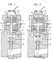
- the electromagnetic actuator 10 includes a first electromagnet, generally indicated at 12, which includes a stator core 14 and a solenoid coil 16 associated with the stator core 14.
- a second electromagnet, generally indicated at 18, is disposed generally in opposing relation to the first electromagnet 12.
- the second electromagnet includes a stator core 20 and a solenoid coil 22 associated with the stator core 20.
- the electromagnetic actuator 10 includes an armature 24 which is attached to a stem 26 of a cylinder valve 28 through a hydraulic valve adjuster 27.
- the armature 24 is disposed generally between the electromagnets 12 and 18 so as to be acted upon by the electromagnetic force created by the electromagnets.
- the armature 24 In a deenergized state of the electromagnets 12 and 18, the armature 24 is maintained in a position of rest (a resetting position) generally between the two electromagnets 12 and 18 by opposing working return springs 30 and 32.
- a valve close position In a valve close position (FIG 2), the armature 24 engages the stator core 14 of the first electromagnet 12.
- a holding current through solenoid coil 16 of the first electromagnet 12 is discontinued, As a result, a holding force of the electromagnet 12 falls below the spring force of the return spring 30 and thus the armature 24 begins its motion accelerated by the return spring 30.
- a catch current is applied to the electromagnet 18. Once the armature has landed at the stator core 20, the catch current is changed to a hold current which is sufficient to hold the armature at the stator core 20 for a predetermined period of time.
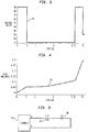
- FIG. 3 shows a system voltage timing waveform 31 of coil 16 of the electromagnetic actuator 10 in an open loop mode of operation
- FIG. 4 is a simplified flux waveform 33 of the electromagnetic actuator 10 in an open loop mode of operation as obtained by a Hall sensor.
- a solenoid coil e.g., coil 16
- flux begins to build up until T1.
- T1 the voltage is removed and as the armature 24 is moving across the gap 32, there is only a slight amount flux increase,
- T2 the voltage is re-applied to the coil 16, the flux increases rapidly and at time T3 the voltage is reduced to provide a holding current.
- values can be calculated for time T1, T2 and T3 to achieve a desirable soft landing of the armature 24 against a stator core. In practice, however, this is almost never achievable because the system is constantly being perturbed by real world variation parameters such as damping, temperature, deflections, tolerance stack up, vibration, engine gas loads, etc.
- coil 16 (FIG. 5) is connected electrically to a programable current regulator 34. Description of operation is made with regard to coil 16 and core 14 of the first electromagnet. It can be appreciated that this description applies to the operation of the second electromagnet as well, As is commonly employed, a current level of a sufficiently large value is initially commanded in the solenoid coil 16 to achieve rapid movement of the armature 24 through its stroke. The current level is then reduced to a value just enough to hold the armature 24 in contact with the associated stator core 14 until the end of a desired cycle for the actuator 10 at which time current is reduced zero. As shown in FIG.
- the solenoid coil 16 has been represented as a pure inductance in series with its internal resistance 36 and the current regulator 34 is a "black box equivalent",
- the resistance R is essentially constant during this analysis but the inductance L(t) is seen to be time varying as a function of (primarily) the position of the armature and (secondarily) the magnetic hysteresis properties with respect to magnetomotive force induced in the ferrous material of the armature 24 and associated stator core 14.
- the EMF of a coil having N number of turns equals the product of the number of turns times the rate of change of flux in the coil 16.
- the coil EMF is quite large during activation of the armature (100 volts typical) while the IR drop term in Equation 1 is small enough to be negligible for the purpose of sensing the rate of change of flux (6 to 8 volts typical). Therefore, the terminal voltage on the coil 16 is nearly in exact proportion to the time rate of change of the flux in the actuator 10 during operation. Thus, this terminal voltage can be utilized as a feedback variable to control soft landing of the armature 24 of the electromagnetic actuator 10, without the need for any external flux sensor.
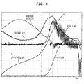
- FIG. 6 shows waveforms of an actuator of the invention including a terminal voltage of a coil of the actuator, an integral of the terminal voltage, magnetic flux as obtained by a flux sensor for comparative purposes, and the derivative of the magnetic flux.
- the applicants have determined a relationship exists between the terminal voltage and the derivative of magnetic flux. This relationship is clearly shown in FIG. 6.
- the integral of the terminal voltage is seen to be proportional to the level of magnetic flux in the armature-stator magnetic circuit.
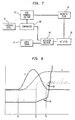
- FIG. 7 a block diagram of an operating circuit according to one embodiment of the present invention is shown.
- the circuit is based on controlling the armature velocity near landing by regulating a rate of change of magnetic flux in the armature/stator magnetic circuit by measuring the terminal voltage of the coil.
- a terminal voltage 36 of a coil 16 is applied to a comparator 38.
- a threshold level 40 is also applied to the comparator 38.
- the output of the comparator 38 is "logically added" with a logic timing component 42 and is supplied to a drive circuit 44 to drive an actuator 10. Once the actuator driver is energized, the solenoid coil 16 is energized.
- the measured coil terminal voltage 36 corresponding to the rate of change of magnetic flux, is compared to the threshold level 40.
- the threshold level 40 is set at a desired rate of change of magnetic flux at certain operating conditions of the actuator to produce a soft landing of the armature. If the terminal voltage 36 is above the threshold level 40, the catch current supplied to the solenoid coil 16 is decreased, and if the terminal voltage 36 is below the threshold level 40, the catch current supplied to the solenoid coil 16 is increased, thus controlling the magnetic flux 41 between T2 and T3 as indicated in FIG. 8.
- This is a closed loop control and the velocity waveform labeled "V" in FIG. 8 illustrates the landing velocity near zero at or near T3.
- the magnetic flux waveform obtained from a flux sensor is indicated at "F" in FIG.
- the current waveform of a coil is indicated at "I” in FIG. 8.
- the dip 46 in the current when the armature 24 seats at a stator core is illustrated.
- the wave shape labeled "A” in FIG. 8 indicates the movement of the armature 24 from an initial position to a landing position at a stator core.
- the flux buildup is generally linear near impact of the armature 24 with a stator core, e.g., core 14.
- the buildup of the flux in this region 45 between T2 and T3 is controlled by controlling the catch current and defines an inclined line.
- the flux is inhibited, modulating the magnetic force from the receiving stator core 14 and coil 16 and causing the velocity of the armature 24 to approach zero.
- the flux is no longer inhibited and the armature 24 is held against the stator core 14.
- the final value of flux which is the force on the armature, is set at T3 to the hold current so as to just exceed the opposing spring force created by spring 30. This permits rapid release of the armature 24 at the beginning of the next stroke of the valve 28. In addition, the hold current minimizes the power required to control the actuator 10.
- CMRR common mode rejection ratio
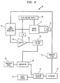
- a mirror image of the coil terminal voltage and hence a mirror image of the rate of change of flux in the actuator's magnetic circuit is provided by the circuit of the actuator 10 such that there is no need to physically monitor the coil terminals to measure the coil terminal voltage.
- FIG. 9 shows a block diagram of a mirror circuit 43 the actuator 10 provided in accordance with the principles of the present invention.
- the solenoid coil 16 of the actuator 10 is driven preferably by a pulse width modulation (PWM) (switchmode) current regulator 50 which provides a pulse train to a high voltage power transistor stage (including a high operating voltage supply 52 and a power switch 54) which subsequently switches voltage pulses across the load of the coil 16.
- PWM pulse width modulation
- switchmode switching mode
- the flux mirror addition to this conventional approach consists of routing the logic level PWM signal from the current regulator 50 through a buffer 56.
- the rail voltage of the buffer 56 is derived from a scaled-down replica of the system high voltage supply 52.
- the scaled and buffered pulse train 58 is smoothed by a low pass filter 60.
- the time constant of the low pass filter 60 is selected to match the rate of armature motion in the actuator 10.
- the output from the low pass filter 60 is scaled-down from and mirroring the high operating voltage of the coil and corresponds to the desired time rate of change of magnetic flux d(phi)/dt which is used as a feedback variable to control the landing velocity of the armature 24 in the manner discussed above.
- the mirror circuit of the invention is much less troublesome to implement in real world applications due to the reduction or elimination of problems caused by both CMRR requirements and interference from high dV/dt.
- FIG. 10 shows waveforms of an electromagnetic actuator 10 being controlled by the mirror circuit of FIG. 8.
- V is the armature velocity which, as shown, decreases to zero near T3.
- the coil current is indicated at “I” and the dip 46 in the current occurs at T3,
- the actual magnetic flux is indicated at "F” which was obtained by a flux sensor and is illustrated for comparative purposes.
- the rate of change of magnetic flux d(phi)/dt is shown which corresponds to a parametrically determined voltage obtained from the mirror circuit of FIG. 9.
- the applicants have found that the rate of change of magnetic flux d(phi)/dt is controlled to be generally constant between T2 and T3 which is found to be optimal for providing the desired soft landing of the armature 24 at a stator core.
Landscapes
- Engineering & Computer Science (AREA)
- Chemical & Material Sciences (AREA)
- Electromagnetism (AREA)
- Nanotechnology (AREA)
- Physics & Mathematics (AREA)
- Health & Medical Sciences (AREA)
- General Health & Medical Sciences (AREA)
- Molecular Biology (AREA)
- Life Sciences & Earth Sciences (AREA)
- Crystallography & Structural Chemistry (AREA)
- Power Engineering (AREA)
- Mechanical Engineering (AREA)
- General Engineering & Computer Science (AREA)
- Magnetically Actuated Valves (AREA)
- Valve Device For Special Equipments (AREA)
- Control Of Linear Motors (AREA)
- Reciprocating, Oscillating Or Vibrating Motors (AREA)
Applications Claiming Priority (6)
| Application Number | Priority Date | Filing Date | Title |
|---|---|---|---|
| US8335198P | 1998-04-28 | 1998-04-28 | |
| US8332998P | 1998-04-28 | 1998-04-28 | |
| US83351P | 1998-04-28 | ||
| US83329P | 1998-04-28 | ||
| US09/122,042 US5991143A (en) | 1998-04-28 | 1998-07-24 | Method for controlling velocity of an armature of an electromagnetic actuator |
| US122042 | 1998-07-24 |
Publications (3)
| Publication Number | Publication Date |
|---|---|
| EP0959479A2 true EP0959479A2 (fr) | 1999-11-24 |
| EP0959479A3 EP0959479A3 (fr) | 2002-08-14 |
| EP0959479B1 EP0959479B1 (fr) | 2003-11-19 |
Family
ID=27374506
Family Applications (1)
| Application Number | Title | Priority Date | Filing Date |
|---|---|---|---|
| EP99105732A Expired - Lifetime EP0959479B1 (fr) | 1998-04-28 | 1999-03-22 | Procédé de régulation pour la vitesse de l'armature d'un actionneur électromagnétique |
Country Status (4)
| Country | Link |
|---|---|
| US (1) | US5991143A (fr) |
| EP (1) | EP0959479B1 (fr) |
| JP (1) | JP2000060174A (fr) |
| DE (1) | DE69912877T2 (fr) |
Cited By (14)
| Publication number | Priority date | Publication date | Assignee | Title |
|---|---|---|---|---|
| DE10010756A1 (de) * | 2000-03-04 | 2001-09-06 | Daimler Chrysler Ag | Verfahren zur Regelung des Bewegungsverlaufs eines Ankers |
| EP1152129A1 (fr) * | 2000-05-04 | 2001-11-07 | MAGNETI MARELLI S.p.A. | Procédé et dispositif pour déterminer la position de l'armature d'un actionneur électromagnétique pour contrôler une soupape de moteur |
| EP1108861A3 (fr) * | 1999-12-17 | 2001-11-07 | MAGNETI MARELLI S.p.A. | Procédé de commande d'actionneur électromagnétiques de soupapes d'admission et d'échappement de moteur à combustion interne |
| FR2812683A1 (fr) * | 2000-08-01 | 2002-02-08 | Sagem | Procede et dispositif de commande de soupape a commande electromagnetique |
| EP1106790A3 (fr) * | 1999-11-30 | 2002-02-13 | MAGNETI MARELLI S.p.A. | Procédé de commande d'actionneurs electromagnétiques pour soupapes d'admission et d'échappement de moteur à combustion interne |
| EP1152251A3 (fr) * | 2000-05-04 | 2002-06-12 | MAGNETI MARELLI S.p.A. | Procédé et dispositif d'estimation d'un flux magnétique dans un actionneur électromagnétique de commande d'une soupape de moteur à combustion interne |
| EP1190161A4 (fr) * | 2000-04-26 | 2002-07-10 | Visteon Global Tech Inc | Soupape de moteur a commande electrique fournissant un signal de position |
| EP1190162A4 (fr) * | 2000-04-27 | 2002-07-10 | Visteon Global Tech Inc | Actuateur pour soupape de moteur avec armature a dents et douilles et noyau |
| EP1209328A3 (fr) * | 2000-11-21 | 2002-09-25 | MAGNETI MARELLI POWERTRAIN S.p.A. | Commande d'un actionneur électromagnétique de soupape de moteur |
| US6476599B1 (en) | 1999-03-25 | 2002-11-05 | Siemens Automotive Corporation | Sensorless method to determine the static armature position in an electronically controlled solenoid device |
| EP1231361A3 (fr) * | 2001-02-13 | 2003-01-08 | MAGNETI MARELLI POWERTRAIN S.p.A. | Procédé d'estimation de la courbe de magnétisation d'un actionneur électromagnétique de soupape |
| EP1288450A1 (fr) * | 2001-08-30 | 2003-03-05 | Peugeot Citroen Automobiles SA | Dispositif de commande de soupape pour moteur à combustion interne |
| EP1479879A1 (fr) * | 2003-05-10 | 2004-11-24 | Bayerische Motoren Werke Aktiengesellschaft | Dispositif électromagnétique de soupape avec circuit de courants de Foucault pour arrêtement passif du rotor |
| EP1106791A3 (fr) * | 1999-12-03 | 2007-08-15 | Nissan Motor Company, Limited | Système électronique de commande pour un actuateur électromagnétique |
Families Citing this family (51)
| Publication number | Priority date | Publication date | Assignee | Title |
|---|---|---|---|---|
| DE59910632D1 (de) * | 1998-07-17 | 2004-11-04 | Bayerische Motoren Werke Ag | Verfahren zur Bewegungssteuerung eines Ankers eines elektromagnetischen Aktuators |
| JP2002529842A (ja) * | 1998-11-06 | 2002-09-10 | シーメンス オートモーティヴ コーポレイション | 電気機械アクチュエーターの流量制御のための補償方法 |
| US6128175A (en) * | 1998-12-17 | 2000-10-03 | Siemens Automotive Corporation | Apparatus and method for electronically reducing the impact of an armature in a fuel injector |
| US6359435B1 (en) * | 1999-03-25 | 2002-03-19 | Siemens Automotive Corporation | Method for determining magnetic characteristics of an electronically controlled solenoid |
| JP2000304153A (ja) * | 1999-04-19 | 2000-11-02 | Honda Motor Co Ltd | 電磁石アクチュエータ駆動装置 |
| US6657847B1 (en) | 1999-07-13 | 2003-12-02 | Siemens Automotive Corporation | Method of using inductance for determining the position of an armature in an electromagnetic solenoid |
| WO2001071823A2 (fr) * | 2000-03-22 | 2001-09-27 | Siemens Vdo Automotive Corporation | Procede de commande d'un actionneur magnetostrictif a detection autonome |
| JP2002231530A (ja) * | 2001-02-07 | 2002-08-16 | Honda Motor Co Ltd | 電磁アクチュエータ制御装置 |
| US20030107015A1 (en) * | 2001-12-11 | 2003-06-12 | Visteon Global Technologies, Inc | Method for estimating the position and the velocity of an EMVA armature |
| US6741441B2 (en) * | 2002-02-14 | 2004-05-25 | Visteon Global Technologies, Inc. | Electromagnetic actuator system and method for engine valves |
| US6889121B1 (en) * | 2004-03-05 | 2005-05-03 | Woodward Governor Company | Method to adaptively control and derive the control voltage of solenoid operated valves based on the valve closure point |
| JP5092206B2 (ja) * | 2005-06-09 | 2012-12-05 | シンフォニアテクノロジー株式会社 | リニアアクチュエータの位置決め制御方法及び装置 |
| US7483253B2 (en) * | 2006-05-30 | 2009-01-27 | Caterpillar Inc. | Systems and methods for detecting solenoid armature movement |
| US7415950B2 (en) * | 2007-01-25 | 2008-08-26 | Ford Global Technologies, Llc | Engine valve control system and method |
| US8132548B2 (en) * | 2007-01-25 | 2012-03-13 | Ford Global Technologies, Llc | Engine valve control system and method |
| US9285653B2 (en) | 2012-11-06 | 2016-03-15 | Raytheon Company | Variable aperture mechanism for creating different aperture sizes in cameras and other imaging devices |
| US9254409B2 (en) | 2013-03-14 | 2016-02-09 | Icon Health & Fitness, Inc. | Strength training apparatus with flywheel and related methods |
| US9323130B2 (en) | 2013-06-11 | 2016-04-26 | Raytheon Company | Thermal control in variable aperture mechanism for cryogenic environment |
| US9228645B2 (en) | 2013-06-11 | 2016-01-05 | Raytheon Company | Vacuum stable mechanism drive arm |
| US9448462B2 (en) | 2013-06-11 | 2016-09-20 | Raytheon Company | Pulse width modulation control of solenoid motor |
| JP6221828B2 (ja) * | 2013-08-02 | 2017-11-01 | 株式会社デンソー | 高圧ポンプの制御装置 |
| EP3623020B1 (fr) | 2013-12-26 | 2024-05-01 | iFIT Inc. | Mécanisme de résistance magnétique dans une machine de câble |
| WO2015138339A1 (fr) | 2014-03-10 | 2015-09-17 | Icon Health & Fitness, Inc. | Capteur de pression pour quantifier un travail |
| US10426989B2 (en) | 2014-06-09 | 2019-10-01 | Icon Health & Fitness, Inc. | Cable system incorporated into a treadmill |
| US10258828B2 (en) | 2015-01-16 | 2019-04-16 | Icon Health & Fitness, Inc. | Controls for an exercise device |
| DE102015206729B4 (de) * | 2015-04-15 | 2025-09-11 | Schaeffler Technologies AG & Co. KG | Verfahren zum Steuern eines Kraftstoffeinspritz-Magnetventils und entsprechendes Motorsteuergerät |
| US10537764B2 (en) | 2015-08-07 | 2020-01-21 | Icon Health & Fitness, Inc. | Emergency stop with magnetic brake for an exercise device |
| US10953305B2 (en) | 2015-08-26 | 2021-03-23 | Icon Health & Fitness, Inc. | Strength exercise mechanisms |
| US10493349B2 (en) | 2016-03-18 | 2019-12-03 | Icon Health & Fitness, Inc. | Display on exercise device |
| US10272317B2 (en) | 2016-03-18 | 2019-04-30 | Icon Health & Fitness, Inc. | Lighted pace feature in a treadmill |
| US10293211B2 (en) | 2016-03-18 | 2019-05-21 | Icon Health & Fitness, Inc. | Coordinated weight selection |
| US10625137B2 (en) | 2016-03-18 | 2020-04-21 | Icon Health & Fitness, Inc. | Coordinated displays in an exercise device |
| US10561894B2 (en) | 2016-03-18 | 2020-02-18 | Icon Health & Fitness, Inc. | Treadmill with removable supports |
| US10252109B2 (en) | 2016-05-13 | 2019-04-09 | Icon Health & Fitness, Inc. | Weight platform treadmill |
| US10471299B2 (en) | 2016-07-01 | 2019-11-12 | Icon Health & Fitness, Inc. | Systems and methods for cooling internal exercise equipment components |
| US10441844B2 (en) | 2016-07-01 | 2019-10-15 | Icon Health & Fitness, Inc. | Cooling systems and methods for exercise equipment |
| US10500473B2 (en) | 2016-10-10 | 2019-12-10 | Icon Health & Fitness, Inc. | Console positioning |
| US10376736B2 (en) | 2016-10-12 | 2019-08-13 | Icon Health & Fitness, Inc. | Cooling an exercise device during a dive motor runway condition |
| TWI646997B (zh) | 2016-11-01 | 2019-01-11 | 美商愛康運動與健康公司 | 用於控制台定位的距離感測器 |
| US10625114B2 (en) | 2016-11-01 | 2020-04-21 | Icon Health & Fitness, Inc. | Elliptical and stationary bicycle apparatus including row functionality |
| TWI637770B (zh) | 2016-11-01 | 2018-10-11 | 美商愛康運動與健康公司 | 用於固定式腳踏車的落入式樞軸配置 |
| US10661114B2 (en) | 2016-11-01 | 2020-05-26 | Icon Health & Fitness, Inc. | Body weight lift mechanism on treadmill |
| DE102016121327B4 (de) | 2016-11-08 | 2019-07-04 | Bühler Motor GmbH | Vorrichtung und Verfahren zum Steuern einer Haltebremse sowie ein computer-lesbares Medium |
| TWI680782B (zh) | 2016-12-05 | 2020-01-01 | 美商愛康運動與健康公司 | 於操作期間抵銷跑步機的平台之重量 |
| US10702736B2 (en) | 2017-01-14 | 2020-07-07 | Icon Health & Fitness, Inc. | Exercise cycle |
| TWI722450B (zh) | 2017-08-16 | 2021-03-21 | 美商愛康運動與健康公司 | 用於抗馬達中之軸向衝擊載荷的系統 |
| DE102018214989A1 (de) * | 2017-10-12 | 2019-04-18 | Fresenius Medical Care Deutschland Gmbh | Klemmen |
| US10729965B2 (en) | 2017-12-22 | 2020-08-04 | Icon Health & Fitness, Inc. | Audible belt guide in a treadmill |
| GB202005894D0 (en) * | 2020-04-22 | 2020-06-03 | Wastling Michael | Fast-acting toggling armature uses centring spring |
| CN113576563B (zh) * | 2021-09-02 | 2022-10-04 | 深圳市理康医疗器械有限责任公司 | 一种电磁弹道式冲击波发生器 |
| CN118548202B (zh) * | 2024-04-23 | 2025-10-17 | 北京化工大学 | 一种多电磁铁并联软着陆电磁执行机构 |
Family Cites Families (22)
| Publication number | Priority date | Publication date | Assignee | Title |
|---|---|---|---|---|
| DE2019345C3 (de) * | 1970-04-22 | 1982-12-09 | Voith Getriebe Kg, 7920 Heidenheim | Anordnung zum Beeinflussen des Erregerstromes eines als Antrieb für Mangetventile verwendeten Gleichstrom-Elektromagneten |
| DE2900420A1 (de) * | 1979-01-08 | 1980-07-24 | Bosch Gmbh Robert | Einrichtung zum steuern des stromes durch einen elektromagnetischen verbraucher, insbesondere durch ein elektromagnetisch betaetigbares einspritzventil einer brennkraftmaschine |
| US4368501A (en) * | 1980-09-26 | 1983-01-11 | Dover Corporation | Control of electro-magnetic solenoid |
| US4593658A (en) * | 1984-05-01 | 1986-06-10 | Moloney Paul J | Valve operating mechanism for internal combustion and like-valved engines |
| ES8703213A1 (es) * | 1985-04-25 | 1987-02-16 | Kloeckner Wolfgang Dr | Procedimiento para el accionamiento de una maquina motriz de combustion interna |
| US4690371A (en) * | 1985-10-22 | 1987-09-01 | Innovus | Electromagnetic valve with permanent magnet armature |
| JPH0621531B2 (ja) * | 1988-12-28 | 1994-03-23 | いすゞ自動車株式会社 | 電磁力駆動バルブの制御装置 |
| JP2772534B2 (ja) * | 1989-02-20 | 1998-07-02 | 株式会社いすゞセラミックス研究所 | 電磁力バルブ駆動装置 |
| US4957074A (en) * | 1989-11-27 | 1990-09-18 | Siemens Automotive L.P. | Closed loop electric valve control for I. C. engine |
| DE4140586C2 (de) * | 1991-12-10 | 1995-12-21 | Clark Equipment Co N D Ges D S | Verfahren und Steuereinrichtung zur Steuerung des Stroms durch eine Magnetspule |
| DE4430867A1 (de) * | 1994-08-31 | 1996-03-07 | Licentia Gmbh | Schaltungsanordnung zur Regelung des elektromagnetischen Antriebes eines Schaltgerätes |
| DE4433209C2 (de) * | 1994-09-17 | 2000-02-03 | Mtu Friedrichshafen Gmbh | Einrichtung zur Erkennung des Ankeraufprallzeitpunktes bei Entstromung eines Magnetventils |
| DE4434684A1 (de) * | 1994-09-28 | 1996-04-04 | Fev Motorentech Gmbh & Co Kg | Verfahren zur Steuerung der Ankerbewegung einer elektromagnetischen Schaltanordnung |
| JP3134724B2 (ja) * | 1995-02-15 | 2001-02-13 | トヨタ自動車株式会社 | 内燃機関の弁駆動装置 |
| DE19526683A1 (de) * | 1995-07-21 | 1997-01-23 | Fev Motorentech Gmbh & Co Kg | Verfahren zur Erkennung des Ankerauftreffens an einem elektromagnetisch betätigbaren Stellmittel |
| DE19526681B4 (de) * | 1995-07-21 | 2006-06-22 | Fev Motorentechnik Gmbh | Verfahren zur zeitgenauen Steuerung der Ankerbewegung eines elektromagnetisch betätigbaren Stellmittels |
| DE19529155B4 (de) * | 1995-08-08 | 2007-05-24 | Fev Motorentechnik Gmbh | Verfahren zur Messung des Ventilspiels an einem durch einen elektromagnetischen Aktuator betätigten Gaswechselventil |
| DE19530798A1 (de) * | 1995-08-22 | 1997-02-27 | Fev Motorentech Gmbh & Co Kg | Verfahren zur Erkennung des Auftreffens eines Ankers auf einen Elektromagneten an einer elektromagnetischen Schaltanordnung |
| DE19544207C2 (de) * | 1995-11-28 | 2001-03-01 | Univ Dresden Tech | Verfahren zur modellbasierten Messung und Regelung von Bewegungen an elektromagnetischen Aktoren |
| US5701870A (en) * | 1996-04-15 | 1997-12-30 | Caterpillar Inc. | Programmable fuel injector current waveform control and method of operating same |
| JPH09320841A (ja) * | 1996-05-28 | 1997-12-12 | Toyota Motor Corp | 電磁アクチュエータ制御装置 |
| US5645019A (en) * | 1996-11-12 | 1997-07-08 | Ford Global Technologies, Inc. | Electromechanically actuated valve with soft landing and consistent seating force |
-
1998
- 1998-07-24 US US09/122,042 patent/US5991143A/en not_active Expired - Fee Related
-
1999
- 1999-03-22 DE DE69912877T patent/DE69912877T2/de not_active Expired - Fee Related
- 1999-03-22 EP EP99105732A patent/EP0959479B1/fr not_active Expired - Lifetime
- 1999-04-26 JP JP11118489A patent/JP2000060174A/ja active Pending
Non-Patent Citations (1)
| Title |
|---|
| None |
Cited By (19)
| Publication number | Priority date | Publication date | Assignee | Title |
|---|---|---|---|---|
| US6476599B1 (en) | 1999-03-25 | 2002-11-05 | Siemens Automotive Corporation | Sensorless method to determine the static armature position in an electronically controlled solenoid device |
| EP1106790A3 (fr) * | 1999-11-30 | 2002-02-13 | MAGNETI MARELLI S.p.A. | Procédé de commande d'actionneurs electromagnétiques pour soupapes d'admission et d'échappement de moteur à combustion interne |
| EP1106791A3 (fr) * | 1999-12-03 | 2007-08-15 | Nissan Motor Company, Limited | Système électronique de commande pour un actuateur électromagnétique |
| EP1108861A3 (fr) * | 1999-12-17 | 2001-11-07 | MAGNETI MARELLI S.p.A. | Procédé de commande d'actionneur électromagnétiques de soupapes d'admission et d'échappement de moteur à combustion interne |
| US6671156B2 (en) | 1999-12-17 | 2003-12-30 | MAGNETI MARELLI S.p.A. | Method for controlling electromagnetic actuators for operating induction and exhaust valves of internal combustion engines |
| FR2805847A1 (fr) | 2000-03-04 | 2001-09-07 | Daimler Chrysler Ag | Procede pour regler l'allure de deplacement d'une armature |
| DE10010756A1 (de) * | 2000-03-04 | 2001-09-06 | Daimler Chrysler Ag | Verfahren zur Regelung des Bewegungsverlaufs eines Ankers |
| EP1190161A4 (fr) * | 2000-04-26 | 2002-07-10 | Visteon Global Tech Inc | Soupape de moteur a commande electrique fournissant un signal de position |
| EP1190162A4 (fr) * | 2000-04-27 | 2002-07-10 | Visteon Global Tech Inc | Actuateur pour soupape de moteur avec armature a dents et douilles et noyau |
| US6571823B2 (en) | 2000-05-04 | 2003-06-03 | MAGNETI MARELLI S.p.A. | Method and device for estimating the position of an actuator body in an electromagnetic actuator to control a valve of an engine |
| EP1152129A1 (fr) * | 2000-05-04 | 2001-11-07 | MAGNETI MARELLI S.p.A. | Procédé et dispositif pour déterminer la position de l'armature d'un actionneur électromagnétique pour contrôler une soupape de moteur |
| EP1152251A3 (fr) * | 2000-05-04 | 2002-06-12 | MAGNETI MARELLI S.p.A. | Procédé et dispositif d'estimation d'un flux magnétique dans un actionneur électromagnétique de commande d'une soupape de moteur à combustion interne |
| FR2812683A1 (fr) * | 2000-08-01 | 2002-02-08 | Sagem | Procede et dispositif de commande de soupape a commande electromagnetique |
| US6683775B2 (en) | 2000-11-21 | 2004-01-27 | Magneti Marelli Powertrain S.P.A. | Control method for an electromagnetic actuator for the control of an engine valve |
| EP1209328A3 (fr) * | 2000-11-21 | 2002-09-25 | MAGNETI MARELLI POWERTRAIN S.p.A. | Commande d'un actionneur électromagnétique de soupape de moteur |
| EP1231361A3 (fr) * | 2001-02-13 | 2003-01-08 | MAGNETI MARELLI POWERTRAIN S.p.A. | Procédé d'estimation de la courbe de magnétisation d'un actionneur électromagnétique de soupape |
| FR2829177A1 (fr) * | 2001-08-30 | 2003-03-07 | Peugeot Citroen Automobiles Sa | Dispositif de commande de soupape pour moteur a combustion interne |
| EP1288450A1 (fr) * | 2001-08-30 | 2003-03-05 | Peugeot Citroen Automobiles SA | Dispositif de commande de soupape pour moteur à combustion interne |
| EP1479879A1 (fr) * | 2003-05-10 | 2004-11-24 | Bayerische Motoren Werke Aktiengesellschaft | Dispositif électromagnétique de soupape avec circuit de courants de Foucault pour arrêtement passif du rotor |
Also Published As
| Publication number | Publication date |
|---|---|
| DE69912877T2 (de) | 2004-09-02 |
| DE69912877D1 (de) | 2003-12-24 |
| EP0959479B1 (fr) | 2003-11-19 |
| US5991143A (en) | 1999-11-23 |
| JP2000060174A (ja) | 2000-02-25 |
| EP0959479A3 (fr) | 2002-08-14 |
Similar Documents
| Publication | Publication Date | Title |
|---|---|---|
| EP0959479B1 (fr) | Procédé de régulation pour la vitesse de l'armature d'un actionneur électromagnétique | |
| US6128175A (en) | Apparatus and method for electronically reducing the impact of an armature in a fuel injector | |
| US6476599B1 (en) | Sensorless method to determine the static armature position in an electronically controlled solenoid device | |
| US6176207B1 (en) | Electronically controlling the landing of an armature in an electromechanical actuator | |
| EP1069284B1 (fr) | Méthode de détermination de la position d'une armature d'un électro-aimant à l'aide d'inductance | |
| EP1155425B1 (fr) | Systeme pour commander un actionneur electromagnetique | |
| US6681728B2 (en) | Method for controlling an electromechanical actuator for a fuel air charge valve | |
| US5708355A (en) | Method of identifying the impact of an armature onto an electromagnet on an electromagnetic switching arrangement | |
| US5917692A (en) | Method of reducing the impact speed of an armature in an electromagnetic actuator | |
| US6397797B1 (en) | Method of controlling valve landing in a camless engine | |
| US5831809A (en) | Method for controlling an electromagnetic actuator with compensation for changes in ohmic resistance of the electromagnet coil | |
| EP1131541B1 (fr) | Procede de compensation pour commande de flux d'un actionneur electromagnetique | |
| Tai et al. | Control of an electromechanical camless valve actuator | |
| CN107429621A (zh) | 控制燃料喷射电磁阀 | |
| US6499447B2 (en) | Process for operating an electromagnetic actuator | |
| US6359435B1 (en) | Method for determining magnetic characteristics of an electronically controlled solenoid | |
| RU2533382C2 (ru) | Исполнительное устройство и способ его регулирования | |
| US6644253B2 (en) | Method of controlling an electromagnetic valve actuator | |
| US5793599A (en) | Control of the attraction of an armature of a switching magnet and a switching arrangement for performing the method | |
| US6418003B1 (en) | Control methods for electromagnetic valve actuators | |
| US7111595B2 (en) | Electromechanical valve control actuator for internal combustion engines | |
| EP1319807B1 (fr) | Méthode pour estimer la position et la vitesse d'une armature d'un actionneur électromagnétique pour la commande d'une soupape de moteur | |
| Chladny et al. | A magnetic flux-based position sensor for control of an electromechanical VVT actuator | |
| EP1049114A2 (fr) | Méthode pour controler l'armature d'un élément de commande électromagnétique à grande vitesse | |
| Chladny et al. | Flatness-based tracking of an electromechanical vvt actuator with magnetic flux sensor |
Legal Events
| Date | Code | Title | Description |
|---|---|---|---|
| PUAI | Public reference made under article 153(3) epc to a published international application that has entered the european phase |
Free format text: ORIGINAL CODE: 0009012 |
|
| AK | Designated contracting states |
Kind code of ref document: A2 Designated state(s): AT BE CH CY DE DK ES FI FR GB GR IE IT LI LU MC NL PT SE |
|
| AX | Request for extension of the european patent |
Free format text: AL;LT;LV;MK;RO;SI |
|
| 17P | Request for examination filed |
Effective date: 20000331 |
|
| PUAL | Search report despatched |
Free format text: ORIGINAL CODE: 0009013 |
|
| AK | Designated contracting states |
Kind code of ref document: A3 Designated state(s): AT BE CH CY DE DK ES FI FR GB GR IE IT LI LU MC NL PT SE |
|
| AX | Request for extension of the european patent |
Free format text: AL;LT;LV;MK;RO;SI |
|
| RAP1 | Party data changed (applicant data changed or rights of an application transferred) |
Owner name: SIEMENS VDO AUTOMOTIVE CORPORATION |
|
| 17Q | First examination report despatched |
Effective date: 20021015 |
|
| AKX | Designation fees paid |
Designated state(s): DE FR IT |
|
| GRAH | Despatch of communication of intention to grant a patent |
Free format text: ORIGINAL CODE: EPIDOS IGRA |
|
| GRAS | Grant fee paid |
Free format text: ORIGINAL CODE: EPIDOSNIGR3 |
|
| GRAA | (expected) grant |
Free format text: ORIGINAL CODE: 0009210 |
|
| AK | Designated contracting states |
Kind code of ref document: B1 Designated state(s): DE FR IT |
|
| REF | Corresponds to: |
Ref document number: 69912877 Country of ref document: DE Date of ref document: 20031224 Kind code of ref document: P |
|
| REG | Reference to a national code |
Ref country code: IE Ref legal event code: FG4D |
|
| PGFP | Annual fee paid to national office [announced via postgrant information from national office to epo] |
Ref country code: DE Payment date: 20040517 Year of fee payment: 6 |
|
| ET | Fr: translation filed | ||
| PLBE | No opposition filed within time limit |
Free format text: ORIGINAL CODE: 0009261 |
|
| STAA | Information on the status of an ep patent application or granted ep patent |
Free format text: STATUS: NO OPPOSITION FILED WITHIN TIME LIMIT |
|
| 26N | No opposition filed |
Effective date: 20040820 |
|
| REG | Reference to a national code |
Ref country code: IE Ref legal event code: MM4A |
|
| PGFP | Annual fee paid to national office [announced via postgrant information from national office to epo] |
Ref country code: FR Payment date: 20050331 Year of fee payment: 7 |
|
| PG25 | Lapsed in a contracting state [announced via postgrant information from national office to epo] |
Ref country code: DE Free format text: LAPSE BECAUSE OF NON-PAYMENT OF DUE FEES Effective date: 20051001 |
|
| PGFP | Annual fee paid to national office [announced via postgrant information from national office to epo] |
Ref country code: IT Payment date: 20060331 Year of fee payment: 8 |
|
| REG | Reference to a national code |
Ref country code: FR Ref legal event code: ST Effective date: 20061130 |
|
| PG25 | Lapsed in a contracting state [announced via postgrant information from national office to epo] |
Ref country code: FR Free format text: LAPSE BECAUSE OF NON-PAYMENT OF DUE FEES Effective date: 20060331 |
|
| PG25 | Lapsed in a contracting state [announced via postgrant information from national office to epo] |
Ref country code: IT Free format text: LAPSE BECAUSE OF NON-PAYMENT OF DUE FEES Effective date: 20070322 |