EP0959525A2 - Antennenanordnung und Funkgerät - Google Patents
Antennenanordnung und Funkgerät Download PDFInfo
- Publication number
- EP0959525A2 EP0959525A2 EP99102339A EP99102339A EP0959525A2 EP 0959525 A2 EP0959525 A2 EP 0959525A2 EP 99102339 A EP99102339 A EP 99102339A EP 99102339 A EP99102339 A EP 99102339A EP 0959525 A2 EP0959525 A2 EP 0959525A2
- Authority
- EP
- European Patent Office
- Prior art keywords
- radiator element
- radio
- reference potential
- radiator
- antenna arrangement
- Prior art date
- Legal status (The legal status is an assumption and is not a legal conclusion. Google has not performed a legal analysis and makes no representation as to the accuracy of the status listed.)
- Granted
Links
- 230000005855 radiation Effects 0.000 claims description 36
- 230000000903 blocking effect Effects 0.000 claims description 6
- 239000004065 semiconductor Substances 0.000 claims description 6
- 230000000694 effects Effects 0.000 description 4
- 238000010586 diagram Methods 0.000 description 2
- 230000003760 hair shine Effects 0.000 description 2
- 230000015572 biosynthetic process Effects 0.000 description 1
- 230000001413 cellular effect Effects 0.000 description 1
- 238000006243 chemical reaction Methods 0.000 description 1
- 238000011161 development Methods 0.000 description 1
- 230000018109 developmental process Effects 0.000 description 1
- 230000002349 favourable effect Effects 0.000 description 1
- 238000005259 measurement Methods 0.000 description 1
- 238000000034 method Methods 0.000 description 1
- 238000010295 mobile communication Methods 0.000 description 1
- 230000010363 phase shift Effects 0.000 description 1
- 230000002265 prevention Effects 0.000 description 1
Images


Classifications
-
- H—ELECTRICITY
- H01—ELECTRIC ELEMENTS
- H01Q—ANTENNAS, i.e. RADIO AERIALS
- H01Q3/00—Arrangements for changing or varying the orientation or the shape of the directional pattern of the waves radiated from an antenna or antenna system
- H01Q3/24—Arrangements for changing or varying the orientation or the shape of the directional pattern of the waves radiated from an antenna or antenna system varying the orientation by switching energy from one active radiating element to another, e.g. for beam switching
-
- H—ELECTRICITY
- H01—ELECTRIC ELEMENTS
- H01Q—ANTENNAS, i.e. RADIO AERIALS
- H01Q1/00—Details of, or arrangements associated with, antennas
- H01Q1/12—Supports; Mounting means
- H01Q1/22—Supports; Mounting means by structural association with other equipment or articles
- H01Q1/24—Supports; Mounting means by structural association with other equipment or articles with receiving set
- H01Q1/241—Supports; Mounting means by structural association with other equipment or articles with receiving set used in mobile communications, e.g. GSM
- H01Q1/242—Supports; Mounting means by structural association with other equipment or articles with receiving set used in mobile communications, e.g. GSM specially adapted for hand-held use
- H01Q1/245—Supports; Mounting means by structural association with other equipment or articles with receiving set used in mobile communications, e.g. GSM specially adapted for hand-held use with means for shaping the antenna pattern, e.g. in order to protect user against rf exposure
-
- H—ELECTRICITY
- H01—ELECTRIC ELEMENTS
- H01Q—ANTENNAS, i.e. RADIO AERIALS
- H01Q21/00—Antenna arrays or systems
- H01Q21/29—Combinations of different interacting antenna units for giving a desired directional characteristic
Definitions
- the invention relates to an antenna arrangement according to the Genus of independent claim 1 and a radio according to the genus of independent claim 8.
- the housing on a first side a hearing device and on one second side opposite the first side Includes antenna element.
- the antenna element is on the second side of the housing is movably mounted and points in at least a first position a directed and in at least a second position is an omnidirectional Radiation pattern on.
- the antenna arrangement according to the invention with the features of The main claim has the advantage that at least a first radiator element and at least a second Radiator element over a reference potential surface are arranged adjacent that a feed of the first radiator element via an antenna network that the second radiator element between a high impedance and one low impedance switchable with the reference potential the reference potential surface is connected that the first Radiating element resonant at the operating wavelength is executed and that the resonance of the second Radiator element compared to the resonance of the first Radiator element is slightly out of tune. That way it is not necessary for an optional switchover between directional and omnidirectional Radiation characteristic of an antenna element movable to be carried out and thus exposed to mechanical wear. Due to the electronically implemented switching between directional radiation pattern and omnidirectional Radiation characteristics are eliminated for the user comparatively cumbersome positioning of a Antenna element, so that ease of use for the user is increased.
- An advantage is that the slight detuning of the Resonance of the second radiator element compared to the Resonance of the first radiator element by varying the geometric dimensions of the second radiator element in Comparison to the geometric dimensions of the first Radiator element can take place. This measure requires little effort and cost in production.
- the second radiator element via a semiconductor component, preferably a PIN diode, to connect with the reference potential. That way the switching process between a high impedance and a low-resistance connection of the second radiator element control electronically with the reference potential.
- Another advantage is that the Semiconductor component switched into a blocking state as soon as it is determined that the connection quality falls below a first predetermined value, and that the Semiconductor component switched into a conductive state is as long as the connection quality is a second exceeds the specified value. That way, at poor connection quality automatically the second Radiator element connected to the reference potential with high resistance and thus an omnidirectional radiation pattern be achieved. Accordingly, with good Connection quality the second radiator element with low resistance to be connected to the reference potential, so that a directed radiation pattern is achieved.
- connection quality automatically between the directional radiation characteristic, for example in the case of a radio, mainly the radiation in the Prevent the user's head, and the omnidirectional radiation pattern that mainly should ensure a good connection quality, can be switched over, when exceeding one predetermined connection quality the prevention of Irradiation in the user's head has priority.
- Another advantage is that the impedance by means of an operating element is switchable. That way the user himself is comparatively simple, that is, without Changing the position of the antenna arrangement for example with regard to the housing of the radio, the Adjust the radiation pattern to your needs.
- a particularly simple, low-effort and cost-saving Embodiment results in a rod-shaped Formation of the first radiator element and the second Radiator element.
- Embodiments of the invention are in the drawing shown and in the following description explained.
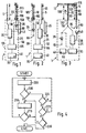
- 1 shows a first embodiment a radio with antenna arrangement according to the invention
- Figure 2 shows a second embodiment of a radio 3 shows a third antenna arrangement according to the invention
- Figure 4 is a flow chart for a Control of the radio with the invention Antenna arrangement
- Figure 5 is a directed Emission characteristics
- Figure 6 is an omnidirectional Radiation pattern.
- 1 denotes a radio, for example a mobile, a cordless phone, a handheld radio, a Company radio, a base station or the like can.
- a radio for example a mobile, a cordless phone, a handheld radio, a Company radio, a base station or the like can.
- the radio 1 includes one Printed circuit board which has a reference potential surface 25.
- the reference potential surface 25 can cover a part or also over the entire printed circuit board as in FIG. 1 expand.
- the reference potential of the reference potential area 25 is identified by the reference symbol 80.
- Above the Reference potential areas 25 are a first on the radio 1 Radiator element 5 and a second radiator element 10 arranged adjacent to each other.
- a hearing device 45 is arranged on a first side surface 50 of the radio device 1, a hearing device 45 is arranged. which can include a speaker in an earpiece.
- a second opposite the first side surface 50 Side surface of the radio device 1 is identified by the reference symbol 55 featured.
- the second radiator element 10 is the one Hearing device 45 of the radio device 1 facing first Side surface 50 facing the first side surface 50 and the third side surface 55 connecting the third Side surface 110 arranged.
- the first radiator element 5 is the second side surface facing away from the hearing device 45 55 arranged on the third side surface 110. There is a height 95 of the first radiator element 5 slightly less than a height 100 of the second Radiator element 10.
- the first radiator element 5 and that second radiator element 10 form an antenna arrangement.
- the Height 95 of the first radiator element 5 is chosen so that the radiator element is operated in its ⁇ / 4 resonance. It is fed by an antenna network 30.
- 10 received signals are from Antenna network 30 after appropriate conversion to Playback forwarded to the hearing device 45.
- the Antenna network 30 is also with a controller 85 of Radio 1 connected to which an input unit 90 with an operating element 40 is connected.
- the controller 85 delivers a control signal to the anode of a PIN diode 35, whose cathode is connected to the reference potential 80.
- the Anode of PIN diode 35 is also with the second one Radiator element 10 connected.
- the reference potential surface 25 forms a counterweight to the antenna arrangement 5, 10. If the control 85 supplies the PIN diode 35 with a high-level control signal, the PIN diode 35 becomes conductive and the second radiator element 10 is connected at its base point 150 to the reference potential 80 with a low resistance .
- the fed first radiator element 5 is resonant at the operating wavelength ⁇ . Due to the greater height 100 of the second antenna element 10 not being fed, its resonance frequency is slightly detuned with respect to the resonance frequency of the first antenna element 5. This results in a phase shift of the current on the second radiator element 10 compared to the fed first radiator element 5 and there is a directional effect.
- FIG. 5 shows a directional diagram of such a directed radiation characteristic 15, the greatest directivity of which occurs at 300 ° and the lowest directivity of which occurs at 120 °.
- the location of the hearing device 45 is therefore in the range from 60 ° to 160 ° according to FIG.
- the controller 85 uses connection data received from the antenna network 30 to check whether the field strength of a currently established radio connection and / or an error measurement of the data stream transmitted during the radio connection and / or the like can determine whether the connection quality exceeds a second predetermined value. This can be checked, for example, by checking in the controller 85 whether the field strength of the connection and / or the error rate of the data stream transmitted during the connection are below a respectively predetermined value.
- the PIN diode 35 is driven by the controller 85 to a high level, so that the antenna arrangement 5, 10 acts as a directional radiator and, due to its radiation characteristic, reduces the radiation of electromagnetic energy into the user's head and at the same time the efficiency of the antenna arrangement 5, 10 is increased.
- the connection quality falls below a first, correspondingly predetermined value, for example in that the radio device 1 is positioned with the antenna arrangement 5, 10 in such a clumsy manner that the antenna arrangement 5, 10 shines in the wrong direction for the current connection
- the controller 85 controls the PIN diode 35 at low level, so that the PIN diode 35 changes to a blocking state and the second radiator element 10 is connected at its base point 150 with high resistance to the reference potential 80.
- the antenna arrangement 5, 10 acts as an omnidirectional radiation pattern, so that the radiation power according to FIG. 6 is approximately the same for all directions and a directional diagram with omnidirectional radiation characteristic 20 results according to FIG.
- the antenna arrangement 5, 10 has the advantage the positive ones automatically in favorable reception situations Using the properties of a directional antenna with special high directivity in a preferred direction. Should the Directional spotlights but clumsily positioned to Example if the radio 1 is on a table and in this radiates in, the radio 1 the wrong way round in the Bag is carried and in the user's body shines, or the like, so will automatically Falling below that specified for the connection quality Upgrade the antenna arrangement 5, 10 Omnidirectional characteristic switched.
- Switching the impedance of the PIN diode 35 between conductive and blocking state or a switchover of Radiation characteristic of the antenna arrangement 5, 10 between directional and omnidirectional radiation pattern can also by means of the control element 40 on the part of User done so that the current Radiation characteristic of the antenna arrangement 5, 10 its Can adapt to needs.
- the effect of the second radiator element 10 in the Antenna arrangement 5, 10 depends on the impedance between the Base 150 of the second radiator element 10 and the Reference potential 80, from the geometric dimensions of the second radiator element 10 compared to the geometric dimensions of the first radiator element 5 and depends on the operating frequency used. If you use the for the GSM standard (Global System for Mobile Communications) provided operating frequency range about 0.9 to 1.0 GHz and chooses a height 105 of the second Radiator element 10, which is slightly smaller than the height 95 of the first radiator element 5 is, for the GSM operating frequency range is also an effect of second radiator element 10 as a reflector if the Impedance between the base 150 of the second Radiator element 10 and the reference potential 80 low is, that is, the PIN diode 35 conducts. In this case it works the antenna arrangement 5, 10 also as a directional radiator Directional radiation pattern from the hearing device 45 path.
- GSM Global System for Mobile Communications
- FIG 2 shows a further embodiment for a Radio 1 with an antenna arrangement 5 according to the invention, 10.
- the radio device according to the invention shown in Figure 2 is there constructed the same as the radio 1 according to Figure 1 and has only the difference is that the first fed Radiator element 5 now the first side surface 50 and that second lamp element 10 of the second not supplied Side surface 55 is facing.
- the required height 105 of the second radiator element 10 is slightly larger than which is still a quarter of the operating wavelength corresponding height 95 of the first radiator element 5 choose so that in this case the second radiator element 10 acts as a director and one away from the hearing device 45 directed radiation pattern is realized.
- the first radiator element 5 and the second radiator element 10 rod-shaped.
- the height 95, 100, 105 des respective radiator element 5, 10 is the height of the arranged above the reference potential surface 25 in each case Staff.
- FIG. 3 is in a with respect to the representation of Figure 1 or FIG. 2 a side view rotated by 90 ° Embodiment shown in which the first Radiator element 5 and the second radiator element 10 F-shaped are trained.
- a first crossbar 60 of the first Radiator element 5 and a first crossbar 65 of the second Radiator element 10 is in each case with the Reference potential 80 connected.
- Feeding the first Radiator element 5 is carried out via a second crossbar 70 of the first radiator element 5.
- the second crossbar 70 of the first radiator element 5 is about Antenna network 30 connected to the controller 85 to which the input unit 90 is connected to the control element 40 is.
- To the antenna network 30 is in turn the Speakers trained hearing device 45 connected, the speaker 45 arranged in an earpiece can be.
- a second crossbar 75 of the second Radiator element 10 is at its base point 150 to the anode the PIN diode 35 connected, also by the controller 85 is controlled.
- the cathode of the PIN diode 35 is with connected to the reference potential 80.
- a longitudinal beam 115 of the first radiator element 5 runs perpendicular to it two crossbars 60, 70, starting with the first crossbar 60, the ends facing away from the reference potential surface 25 connecting these two crossbeams 60, 70 to one another.
- a longitudinal beam 120 connects the two in the same way Crossbar 65, 75 of the second radiator element 10. Instead the longitudinal beams 115, 120 can accordingly areal longitudinal elements are used.
- the second crossbar 75 of the second Radiator element 10 at its base 150 via the PIN diode 35 high-resistance or low-resistance with the reference potential 80 are connected.
- the resonance of the first Radiator element 5 and the second radiator element 10 is no longer determined solely by the height 95, 100, 105 of the respective radiator element 5, 10, but also by the Distance of the first crossbar 60 of the first Radiator element 5 from the second crossbar 70 of the first Radiator element 5 or by the distance of the first Crossbar 65 of the second radiator element 10 from the second Crossbar 75 of the second radiator element 10 and through Length of the longitudinal beam 115, 120 of the respective Radiator element 5, 10 determined, that is, through the entire geometric dimensions of the first radiator element 5 or the second radiator element 10.
- the geometric dimensions of the first radiator element 5 so chosen that a at the operating frequency used Sets resonance.
- the geometric dimensions of the second radiator element 10 are, however, compared to geometric dimensions of the first radiator element 5 so changed that for the resonance of the second Radiator element 10 a slight deviation from the Resonance of the first radiator element 5 results and that second radiator element 10 thus depending on the selected Operating frequency as a reflector or director at each low-resistance connection of base 150 of its second Crossbar 75 with the reference potential 80 in the Antenna arrangement 5, 10 can act.
- the PIN diode 35 is in the conductive state and is the height 100 of the second radiator element 10 for one Operating frequency range from about 1.8 to 1.9 GHz slightly greater than the height 95 of the first radiator element 5, so the second radiator element 10 acts as a reflector and it the first radiator element 5 results in a directional one Radiation characteristic to the second radiator element 10 opposite direction.
- the hearing device 45 should be at the point of Radio 1 may be arranged, which is directed Radiation characteristic of the antenna arrangement 5, 10 die has the least directivity to the radiation in the Keep the user's head as low as possible.
- the antenna arrangement 5 acts, 10 as omnidirectional omnidirectional Radiation pattern.
- FIG 4 is a flow chart for the operation of the Control 85 of the radio 1 with the invention Antenna arrangement 5, 10 shown.
- the controller 85 controls the PIN diode 35 with a high level signal so that the PIN diode 35 conducts and the second radiator element 10 at its base point 150 is connected to the reference potential 80 with low resistance and the Antenna arrangement 5, 10 a directional Has radiation characteristics.
- Program item 205 branches.
- program point 205 checked whether the connection quality under the first according to the specified value and by appropriate Presetting or entering the user on the Input unit 90 allows an omnidirectional characteristic is. If this is the case, then a program point 210 branches, otherwise program point 220 branches.
- At program point 220 it is checked whether at the Input unit 90 by means of control element 40 Input has been made. If this is the case, it becomes one Program point 225 branches, otherwise it becomes Program point 200 branched back. At program point 225 it is checked whether the actuation of the control element 40 a directional radiation pattern chosen by the user has been. If this is the case, then program point 200 it branches back to program point 230 otherwise branches. At program point 230 it is checked whether that Radio 1 was turned off. If this is the case, then leave the program part. Otherwise, the user an omnidirectional by means of the control element 40 Beam pattern selected and for program item 210 branches.
- the controller 85 controls at program point 210 the PIN diode 35 with a low level signal, so that the PIN diode 35 goes into the blocking state and the Antenna arrangement 5, 10 an omnidirectional Has radiation characteristics. Then becomes one Program item 215 branches. At program point 215 checked whether the connection quality over a second predetermined value, which is preferably above the first predetermined value is too frequent and unnecessary Avoid switching the PIN diode 35. Is that the case, the program branches back to program point 200 and on directional radiation pattern switched. Otherwise is branched back to program point 210 and the Antenna arrangement 5, 10 continues with omnidirectional Radiation characteristics operated.
- each switchable very high impedance or very low-resistance at its base with the reference potential 80 are connectable. With a low-impedance connection the not fed radiator elements at their base with the An antenna arrangement can be used with reference potential 80 realize correspondingly improved directivity.
- a PIN diode 35 instead of a PIN diode 35, a conventional pn diode, a transistor, or some other very low-impedance or very high-impedance switchable impedance be provided.
- the necessary for the detuning of the resonance of the second radiator element 10 with respect to the resonance of the first radiator element 5 required height difference two radiator elements 5, 10 is of the order of magnitude one-eighth of the operating wavelength.
Landscapes
- Engineering & Computer Science (AREA)
- Computer Networks & Wireless Communication (AREA)
- Variable-Direction Aerials And Aerial Arrays (AREA)
- Aerials With Secondary Devices (AREA)
- Waveguide Aerials (AREA)
Abstract
Description
Claims (14)
- Antennenanordnung (5, 10), die wahlweise eine gerichtete Abstrahlcharakteristik (15) oder eine omnidirektionale Abstrahlcharakteristik (20)
aufweist, dadurch gekennzeichnet, daß mindestens ein erstes strahlerelement (5) und mindestens ein zweites Strahlerelement (10) über einer Bezugspotentialfläche (25) einander benachbart angeordnet sind, daß eine Speisung des ersten Strahlerelementes (5) über ein Antennennetzwerk (30) erfolgt, daß das zweite Strahlerelement (10) zwischen einer hochohmigen und einer niederohmigen Impedanz (35) umschaltbar mit dem Bezugspotential (80) der Bezugspotentialfläche (25) verbunden ist, daß das erste Strahlerelement (5) bei der Betriebswellenlänge resonant ausgeführt ist und daß die Resonanz des zweiten Strahlerelementes (10) gegenüber der Resonanz des ersten Strahlerelementes (5) leicht verstimmt ist. - Antennenanordnung (5, 10) nach Anspruch 1, dadurch gekennzeichnet, daß die leichte Verstimmung der Resonanz des zweiten Strahlerelementes (10) gegenüber der Resonanz des ersten Strahlerelementes (5) durch Variation der geometrischen Abmessungen des zweiten Strahlerelements (10) im Vergleich zu den geometrischen Abmessungen des ersten Strahlerelements (5) erfolgt.
- Antennenanordnung (5, 10) nach Anspruch 1 oder 2, dadurch gekennzeichnet, daß das zweite Strahlerelement (10) über ein Halbleiterbauelement (35), vorzugsweise eine PIN-Diode, mit dem Bezugspotential (80) verbunden ist.
- Antennenanordnung (5, 10) nach Anspruch 3, dadurch gekennzeichnet, daß das Halbleiterbauelement (35) in einen sperrenden Zustand geschaltet ist, sobald festgestellt wird, daß die Verbindungsqualität einen ersten vorgegebenen Wert unterschreitet, und daß das Halbleiterbauelement (35) in einen leitenden Zustand geschaltet ist, solange die Verbindungsqualität einen zweiten vorgegebenen Wert überschreitet.
- Antennenanordnung (5, 10) nach einem der vorherigen Ansprüche, dadurch gekennzeichnet, daß die Impedanz (35) mittels eines Bedienelementes (40) umschaltbar ist.
- Funkgerät (1) nach einem der vorherigen Ansprüche, dadurch gekennzeichnet, daß das erste Strahlerelement (5) und das zweite Strahlerelement (10) stabförmig ausgebildet sind.
- Funkgerät (1) nach einem der Ansprüche 1 bis 5, dadurch gekennzeichnet, daß das erste Strahlerelement (5) und das zweite Strahlerelement (10) F-förmig ausgebildet sind, daß ein erster Querbalken (60) des ersten Strahlerelementes (5) und ein erster Querbalken (65) des zweiten Strahlerelementes (10) jeweils mit dem Bezugspotential (80) verbunden ist, daß die Speisung des ersten Strahlerelementes (5) über einen zweiten Querbalken (70) des ersten Strahlerelementes (5) erfolgt, daß ein zweiter Querbalken (75) des zweiten Strahlerelementes (10) zwischen der hochohmigen und der niederohmigen Impedanz (35) umschaltbar mit dem Bezugspotential (80) verbunden ist.
- Funkgerät (1), insbesondere Mobilfunk- oder Schnurlostelefon, mit einer Antennenanordnung (5, 10) nach einem der vorherigen Ansprüche.
- Funkgerät (1) nach Anspruch 8, dadurch gekennzeichnet, daß das zweite Strahlerelement (10) einer einer Hörvorrichtung (45) des Funkgerätes (1) zugewandten Seitenfläche (50) des Funkgerätes (1) zugewandt angeordnet ist und daß die geometrischen Abmessungen des zweiten Strahlerelementes (10, 10') im Vergleich zu den geometrischen Abmessungen des ersten Strahlerelementes (5) so gewählt sind, daß das zweite Strahlerelement (10) in einem Betriebsfrequenzbereich als Reflektor wirkt und daß das erste Strahlerelement (5) einer der Hörvorrichtung (45) des Funkgerätes (1) abgewandten Seitenfläche (55) des Funkgerätes (1) zugewandt angeordnet ist.
- Funkgerät (1) nach Anspruch 8, dadurch gekennzeichnet, daß das erste Strahlerelement (5) einer einer Hörvorrichtung (45) des Funkgerätes (1) zugewandten Seitenfläche (50) des Funkgerätes (1) zugewandt angeordnet ist und daß das zweite Strahlerelement (10) einer der Hörvorrichtung (45) des Funkgerätes (1) abgewandten Seitenfläche (55) des Funkgerätes (1) zugewandt angeordnet ist und daß die geometrischen Abmessungen des zweiten Strahlerelementes (10) im Vergleich zu den geometrischen Abmessungen des ersten Strahlerelementes (5) so gewählt sind, daß das zweite Strahlerelement (10) in einem Betriebsfrequenzbereich als Direktor wirkt.
- Funkgerät (1) nach Anspruch 9, dadurch gekennzeichnet, daß das zweite Strahlerelement (10) höher über der Bezugspotentialfläche (25) als das erste Strahlerelement (5) ist und daß als Betriebsfreguenzbereich etwa 1,8 bis 1,9 GHz vorgesehen sind.
- Funkgerät (1) nach Anspruch 10, dadurch gekennzeichnet, daß das erste Strahlerelement (5) höher über der Bezugspotentialfläche (25) als das zweite Strahlerelement (10) ist und daß als Betriebsfrequenzbereich etwa 1,8 bis 1,9 GHz vorgesehen sind.
- Funkgerät (1) nach Anspruch 9, dadurch gekennzeichnet, daß das erste Strahlerelement (5) höher über der Bezugspotentialfläche (25) als das zweite Strahlerelement (10) ist und daß als Betriebsfrequenzbereich etwa 0,9 bis 1,0GHz vorgesehen sind.
- Funkgerät (1) nach Anspruch 10, dadurch gekennzeichnet, daß das zweite Strahlerelement (10) höher über der Bezugspotentialfläche (25) als das erste Strahlerelement (5) ist und daß als Betriebsfrequenzbereich etwa 0,9 bis 1,0GHz vorgesehen sind.
Applications Claiming Priority (2)
| Application Number | Priority Date | Filing Date | Title |
|---|---|---|---|
| DE1998123126 DE19823126B4 (de) | 1998-05-23 | 1998-05-23 | Funkgerät |
| DE19823126 | 1998-05-23 |
Publications (3)
| Publication Number | Publication Date |
|---|---|
| EP0959525A2 true EP0959525A2 (de) | 1999-11-24 |
| EP0959525A3 EP0959525A3 (de) | 2001-04-04 |
| EP0959525B1 EP0959525B1 (de) | 2009-05-13 |
Family
ID=7868738
Family Applications (1)
| Application Number | Title | Priority Date | Filing Date |
|---|---|---|---|
| EP19990102339 Expired - Lifetime EP0959525B1 (de) | 1998-05-23 | 1999-02-06 | Antennenanordnung und Funkgerät |
Country Status (3)
| Country | Link |
|---|---|
| EP (1) | EP0959525B1 (de) |
| DE (2) | DE19823126B4 (de) |
| ES (1) | ES2324747T3 (de) |
Cited By (5)
| Publication number | Priority date | Publication date | Assignee | Title |
|---|---|---|---|---|
| FR2797136A1 (fr) * | 1999-07-02 | 2001-02-02 | Ninebell United Technology Co | Dispositif de protection contre le rayonnement electromagnetique d'un telephone mobile |
| EP1109247A1 (de) * | 1999-12-17 | 2001-06-20 | Siemens Aktiengesellschaft | Mobiltelephon und Verfahren zur Steuerung der in den Körper eines Nutzers gesendeten Strahlung |
| EP1206001A1 (de) * | 2000-11-14 | 2002-05-15 | Northrop Grumman Corporation | Array-Antenne für ein zellulares Telephon |
| WO2004013935A1 (en) * | 2002-08-01 | 2004-02-12 | Koninklijke Philips Electronics N.V. | Directional dual frequency antenna arrangement |
| EP1618752A4 (de) * | 2003-04-25 | 2006-05-24 | Motorola Inc | Drahtloses kommunikationsgerät mit variablem antennenstrahlungsmuster und entsprechendes verfahren |
Citations (4)
| Publication number | Priority date | Publication date | Assignee | Title |
|---|---|---|---|---|
| US3725938A (en) | 1970-10-05 | 1973-04-03 | Sperry Rand Corp | Direction finder system |
| US4700197A (en) | 1984-07-02 | 1987-10-13 | Canadian Patents & Development Ltd. | Adaptive array antenna |
| JPH1075192A (ja) | 1996-08-30 | 1998-03-17 | Matsushita Electric Ind Co Ltd | アンテナ装置 |
| DE19723331A1 (de) | 1997-06-04 | 1998-12-10 | Bosch Gmbh Robert | Funkgerät |
Family Cites Families (3)
| Publication number | Priority date | Publication date | Assignee | Title |
|---|---|---|---|---|
| AT393054B (de) * | 1989-07-27 | 1991-08-12 | Siemens Ag Oesterreich | Sende- und/oder empfangsanordnung fuer tragbare geraete |
| ATE250809T1 (de) * | 1993-05-27 | 2003-10-15 | Univ Griffith | Antennen für tragbare kommunikationsgeräte |
| DE4334439A1 (de) * | 1993-10-09 | 1995-04-13 | Philips Patentverwaltung | Funkgerät mit einer Antenne |
-
1998
- 1998-05-23 DE DE1998123126 patent/DE19823126B4/de not_active Expired - Lifetime
-
1999
- 1999-02-06 EP EP19990102339 patent/EP0959525B1/de not_active Expired - Lifetime
- 1999-02-06 DE DE59915023T patent/DE59915023D1/de not_active Expired - Lifetime
- 1999-02-06 ES ES99102339T patent/ES2324747T3/es not_active Expired - Lifetime
Patent Citations (4)
| Publication number | Priority date | Publication date | Assignee | Title |
|---|---|---|---|---|
| US3725938A (en) | 1970-10-05 | 1973-04-03 | Sperry Rand Corp | Direction finder system |
| US4700197A (en) | 1984-07-02 | 1987-10-13 | Canadian Patents & Development Ltd. | Adaptive array antenna |
| JPH1075192A (ja) | 1996-08-30 | 1998-03-17 | Matsushita Electric Ind Co Ltd | アンテナ装置 |
| DE19723331A1 (de) | 1997-06-04 | 1998-12-10 | Bosch Gmbh Robert | Funkgerät |
Cited By (6)
| Publication number | Priority date | Publication date | Assignee | Title |
|---|---|---|---|---|
| FR2797136A1 (fr) * | 1999-07-02 | 2001-02-02 | Ninebell United Technology Co | Dispositif de protection contre le rayonnement electromagnetique d'un telephone mobile |
| EP1109247A1 (de) * | 1999-12-17 | 2001-06-20 | Siemens Aktiengesellschaft | Mobiltelephon und Verfahren zur Steuerung der in den Körper eines Nutzers gesendeten Strahlung |
| EP1206001A1 (de) * | 2000-11-14 | 2002-05-15 | Northrop Grumman Corporation | Array-Antenne für ein zellulares Telephon |
| US6437746B1 (en) | 2000-11-14 | 2002-08-20 | Northrop Grumman Corp | Cellular telephone antenna array |
| WO2004013935A1 (en) * | 2002-08-01 | 2004-02-12 | Koninklijke Philips Electronics N.V. | Directional dual frequency antenna arrangement |
| EP1618752A4 (de) * | 2003-04-25 | 2006-05-24 | Motorola Inc | Drahtloses kommunikationsgerät mit variablem antennenstrahlungsmuster und entsprechendes verfahren |
Also Published As
| Publication number | Publication date |
|---|---|
| EP0959525A3 (de) | 2001-04-04 |
| DE19823126B4 (de) | 2012-08-23 |
| EP0959525B1 (de) | 2009-05-13 |
| DE59915023D1 (de) | 2009-06-25 |
| ES2324747T3 (es) | 2009-08-13 |
| DE19823126A1 (de) | 1999-11-25 |
Similar Documents
| Publication | Publication Date | Title |
|---|---|---|
| DE69828113T2 (de) | Doppelresonanzantennenstruktur für mehrere Frequenzbereiche | |
| DE60001709T2 (de) | Möglichkeit zur Korrektur des Strahlungsdiagramms einer linearen Antenne | |
| DE10226910B4 (de) | Oberflächenmontierbare Antenne und Verwendung derselben | |
| DE69433150T2 (de) | Antennenvorrichtung | |
| DE60316666T2 (de) | Mehrbandantenne mit Streifenleiter- und Schlitzstrukturen | |
| DE60306513T2 (de) | Antennenanordnung | |
| DE60133703T2 (de) | Eingebaute Zweibandantenne und Verfahren zum Betrieb dieser Antenne in einem mobilen Terminal | |
| EP1204160B1 (de) | Mehrband-Mikrowellenantenne | |
| DE60209686T2 (de) | Interne Mehrbandantenne | |
| EP0841715B1 (de) | Flachantenne | |
| DE60313390T2 (de) | Antenne mit variabler Richtcharakteristik | |
| DE60200738T2 (de) | Antenne für mobiles Telefon | |
| DE112008000578B4 (de) | Antenne und Funkkommunikationsvorrichtung | |
| DE69824262T2 (de) | Antenne | |
| DE60026276T2 (de) | Antennenstruktur, Verfahren zur Kopplung eines Signals an die Antennenstruktur, Antenneneinheit und Mobilstation mit einer derartigen Antennenstruktur | |
| DE60126280T2 (de) | Zweiband-patchantenne | |
| DE10347719A1 (de) | Innere Antenne für ein mobiles Kommunikationsgerät | |
| EP1168495A2 (de) | Antennenanordnung für Mobilfunktelefone | |
| DE202015009879U1 (de) | Mehrbandstrahlerarray mit niedriger Gleichtaktresonanz | |
| EP1829158B1 (de) | Disc-monopol-antennenstruktur | |
| DE10292326T5 (de) | Antennenvorrichtung und drahtlose Vorrichtung die diese verwendet | |
| DE602006000352T2 (de) | Antenneneinrichtung und mobiles Endgerät, welches mit der Antenneneinrichtung ausgerüstet ist | |
| EP1237224A1 (de) | Antenne und Verfahren zu deren Herstellung | |
| EP1086509B1 (de) | Antennenanordnung und funkgerät | |
| DE19823126B4 (de) | Funkgerät |
Legal Events
| Date | Code | Title | Description |
|---|---|---|---|
| PUAI | Public reference made under article 153(3) epc to a published international application that has entered the european phase |
Free format text: ORIGINAL CODE: 0009012 |
|
| AK | Designated contracting states |
Kind code of ref document: A2 Designated state(s): CH DE ES FR GB IT LI SE |
|
| AX | Request for extension of the european patent |
Free format text: AL;LT;LV;MK;RO;SI |
|
| PUAL | Search report despatched |
Free format text: ORIGINAL CODE: 0009013 |
|
| AK | Designated contracting states |
Kind code of ref document: A3 Designated state(s): AT BE CH CY DE DK ES FI FR GB GR IE IT LI LU MC NL PT SE |
|
| AX | Request for extension of the european patent |
Free format text: AL;LT;LV;MK;RO;SI |
|
| 17P | Request for examination filed |
Effective date: 20011004 |
|
| AKX | Designation fees paid |
Free format text: CH DE ES FR GB IT LI SE |
|
| RAP1 | Party data changed (applicant data changed or rights of an application transferred) |
Owner name: IPCOM GMBH & CO. KG |
|
| 17Q | First examination report despatched |
Effective date: 20080507 |
|
| GRAP | Despatch of communication of intention to grant a patent |
Free format text: ORIGINAL CODE: EPIDOSNIGR1 |
|
| GRAS | Grant fee paid |
Free format text: ORIGINAL CODE: EPIDOSNIGR3 |
|
| GRAA | (expected) grant |
Free format text: ORIGINAL CODE: 0009210 |
|
| AK | Designated contracting states |
Kind code of ref document: B1 Designated state(s): CH DE ES FR GB IT LI SE |
|
| REG | Reference to a national code |
Ref country code: GB Ref legal event code: FG4D Free format text: NOT ENGLISH |
|
| REG | Reference to a national code |
Ref country code: CH Ref legal event code: EP |
|
| REG | Reference to a national code |
Ref country code: CH Ref legal event code: NV Representative=s name: HEPP WENGER RYFFEL AG |
|
| REF | Corresponds to: |
Ref document number: 59915023 Country of ref document: DE Date of ref document: 20090625 Kind code of ref document: P |
|
| REG | Reference to a national code |
Ref country code: SE Ref legal event code: TRGR |
|
| REG | Reference to a national code |
Ref country code: ES Ref legal event code: FG2A Ref document number: 2324747 Country of ref document: ES Kind code of ref document: T3 |
|
| PLBE | No opposition filed within time limit |
Free format text: ORIGINAL CODE: 0009261 |
|
| STAA | Information on the status of an ep patent application or granted ep patent |
Free format text: STATUS: NO OPPOSITION FILED WITHIN TIME LIMIT |
|
| 26N | No opposition filed |
Effective date: 20100216 |
|
| REG | Reference to a national code |
Ref country code: FR Ref legal event code: PLFP Year of fee payment: 18 |
|
| REG | Reference to a national code |
Ref country code: FR Ref legal event code: PLFP Year of fee payment: 19 |
|
| REG | Reference to a national code |
Ref country code: FR Ref legal event code: PLFP Year of fee payment: 20 |
|
| PGFP | Annual fee paid to national office [announced via postgrant information from national office to epo] |
Ref country code: ES Payment date: 20180322 Year of fee payment: 20 Ref country code: GB Payment date: 20180221 Year of fee payment: 20 Ref country code: CH Payment date: 20180221 Year of fee payment: 20 |
|
| PGFP | Annual fee paid to national office [announced via postgrant information from national office to epo] |
Ref country code: FR Payment date: 20180226 Year of fee payment: 20 Ref country code: SE Payment date: 20180222 Year of fee payment: 20 Ref country code: IT Payment date: 20180221 Year of fee payment: 20 |
|
| PGFP | Annual fee paid to national office [announced via postgrant information from national office to epo] |
Ref country code: DE Payment date: 20180430 Year of fee payment: 20 |
|
| REG | Reference to a national code |
Ref country code: DE Ref legal event code: R071 Ref document number: 59915023 Country of ref document: DE |
|
| REG | Reference to a national code |
Ref country code: CH Ref legal event code: PL |
|
| REG | Reference to a national code |
Ref country code: GB Ref legal event code: PE20 Expiry date: 20190205 |
|
| REG | Reference to a national code |
Ref country code: SE Ref legal event code: EUG |
|
| PG25 | Lapsed in a contracting state [announced via postgrant information from national office to epo] |
Ref country code: GB Free format text: LAPSE BECAUSE OF EXPIRATION OF PROTECTION Effective date: 20190205 |
|
| REG | Reference to a national code |
Ref country code: ES Ref legal event code: FD2A Effective date: 20200902 |
|
| PG25 | Lapsed in a contracting state [announced via postgrant information from national office to epo] |
Ref country code: ES Free format text: LAPSE BECAUSE OF EXPIRATION OF PROTECTION Effective date: 20190207 |