EP0959543A1 - Boítier pour matériel électrique avec fixations pour couvercle et fixations sur support - Google Patents
Boítier pour matériel électrique avec fixations pour couvercle et fixations sur support Download PDFInfo
- Publication number
- EP0959543A1 EP0959543A1 EP98830185A EP98830185A EP0959543A1 EP 0959543 A1 EP0959543 A1 EP 0959543A1 EP 98830185 A EP98830185 A EP 98830185A EP 98830185 A EP98830185 A EP 98830185A EP 0959543 A1 EP0959543 A1 EP 0959543A1
- Authority
- EP
- European Patent Office
- Prior art keywords
- fixing
- base
- box
- seat
- section
- Prior art date
- Legal status (The legal status is an assumption and is not a legal conclusion. Google has not performed a legal analysis and makes no representation as to the accuracy of the status listed.)
- Granted
Links
- 239000002305 electric material Substances 0.000 title claims abstract description 9
- 230000008878 coupling Effects 0.000 description 3
- 238000010168 coupling process Methods 0.000 description 3
- 238000005859 coupling reaction Methods 0.000 description 3
- 238000004026 adhesive bonding Methods 0.000 description 2
- 238000009434 installation Methods 0.000 description 2
- 238000009413 insulation Methods 0.000 description 2
- 238000003466 welding Methods 0.000 description 2
- 230000015572 biosynthetic process Effects 0.000 description 1
- 238000005553 drilling Methods 0.000 description 1
- 239000012776 electronic material Substances 0.000 description 1
- 239000012530 fluid Substances 0.000 description 1
- 238000002347 injection Methods 0.000 description 1
- 239000007924 injection Substances 0.000 description 1
- 238000001746 injection moulding Methods 0.000 description 1
- 239000000463 material Substances 0.000 description 1
- 239000002991 molded plastic Substances 0.000 description 1
- 239000000243 solution Substances 0.000 description 1
Images



Classifications
-
- H—ELECTRICITY
- H02—GENERATION; CONVERSION OR DISTRIBUTION OF ELECTRIC POWER
- H02G—INSTALLATION OF ELECTRIC CABLES OR LINES, OR OF COMBINED OPTICAL AND ELECTRIC CABLES OR LINES
- H02G3/00—Installations of electric cables or lines or protective tubing therefor in or on buildings, equivalent structures or vehicles
- H02G3/02—Details
- H02G3/08—Distribution boxes; Connection or junction boxes
- H02G3/10—Distribution boxes; Connection or junction boxes for surface mounting on a wall
-
- H—ELECTRICITY
- H02—GENERATION; CONVERSION OR DISTRIBUTION OF ELECTRIC POWER
- H02B—BOARDS, SUBSTATIONS OR SWITCHING ARRANGEMENTS FOR THE SUPPLY OR DISTRIBUTION OF ELECTRIC POWER
- H02B1/00—Frameworks, boards, panels, desks, casings; Details of substations or switching arrangements
- H02B1/26—Casings; Parts thereof or accessories therefor
- H02B1/46—Boxes; Parts thereof or accessories therefor
-
- H—ELECTRICITY
- H02—GENERATION; CONVERSION OR DISTRIBUTION OF ELECTRIC POWER
- H02G—INSTALLATION OF ELECTRIC CABLES OR LINES, OR OF COMBINED OPTICAL AND ELECTRIC CABLES OR LINES
- H02G3/00—Installations of electric cables or lines or protective tubing therefor in or on buildings, equivalent structures or vehicles
- H02G3/02—Details
- H02G3/08—Distribution boxes; Connection or junction boxes
- H02G3/14—Fastening of cover or lid to box
-
- H—ELECTRICITY
- H02—GENERATION; CONVERSION OR DISTRIBUTION OF ELECTRIC POWER
- H02B—BOARDS, SUBSTATIONS OR SWITCHING ARRANGEMENTS FOR THE SUPPLY OR DISTRIBUTION OF ELECTRIC POWER
- H02B1/00—Frameworks, boards, panels, desks, casings; Details of substations or switching arrangements
- H02B1/26—Casings; Parts thereof or accessories therefor
- H02B1/28—Casings; Parts thereof or accessories therefor dustproof, splashproof, drip-proof, waterproof or flameproof
Definitions
- the present invention relates to a box for electric material indended to be used in domestic or industrial electric installations as a pull box or as a housing for electric or electronic apparatus.
- the boxes of this type normally comprise a box-shaped base defining an internal volume and an aperture which is intended to be closed by a removable cover.
- the problem on which the present invention is based is to provide a box for electric material in which the internal volume is insulated in a liquid-tight manner from the external environment and in which the seats for fixing the cover and the seats for the means for fixing the box to a wall occupy as a little space as possible.
- this object is achieved by a box having the features forming the subject of the main claim.
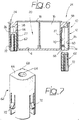
- 10 indicates a box for electric material, comprising a box-shaped base 12 made of injection moulded plastic material.
- the base 12 has a bottom wall 14 and four lateral walls 16 which define an upper aperture 18 and an internal volume 20.
- the lateral walls 16 have circular non-through notches forming lines of preferential breaking which facilitates the formation of through apertures 22 adapted to receive couplings for protection elements for electric installations.
- the walls 16 could also be deprived of such lines of preferential breaking and in this case the apertures 22 could be obtained by means of drilling tools of known type.
- the apertures 22 are intended to receive liquid-tight couplings for example of the type disclosed in a contemporary patent application of the same Applicant titled "A liquid-tight coupling for boxes for electric material".
- the base 12 has four fixing sections 24 arranged at the intersection between each pair of adjacent lateral walls 16.
- Each fixing section 24 has an external wall 26, for example with arcuate shape, which connects to each other two lateral walls 16.
- each fixing section 24 is delimited by a wall 27 formed integrally with the base 12.
- Each wall 27 is joined to the lateral walls 16 along lines 28 and to the bottom wall 14 along a line 30.
- the elements contained within the fixing sections 24 are insulated from the internal volume 20 of the base 12.
- an element is insulated from the internal volume 20 it is meant that such element is not in fluid contact with any part of the volume 20 in the condition in which the upper aperture 18 of the base 12 is closed by a suitable cover.
- insulated from the internal volume furthermore refers to an insulation of electric type.
- the solution according to the invention has the object to obtain, in addition to liquid-tightness, an electric insulation of class II and to reduce the unused space.
- Each fixing section 24 contains a first seat adapted to receive means for fixing to the base 12 a removable cover (not shown) adapted to close the aperture 18 and a second seat adapted to receive means for fixing the base 12 to a support wall.
- each fixing section 24 has a monolithic block 22 integrally formed with the base 12.
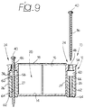
- the block 32 has a smooth through hole 34 through which can extend a screw 36 intended for example to engage a screw-anchor inserted in the support wall.
- the block 32 has an upper abutment surface 38 against which is intended to abut the head 40 of the screw 36.
- Each fixing section 24 above the block 32 has an upwardly open cavity 42 in which is inserted and fixed a separated element 44 in which is formed a seat 46 for the engagement of the means for fixing the cover.
- the seat 46 is arranged substantially coaxially with the through hole 34 forming the seat for the screw 36.
- the coaxial arrangement of the two seats 46, 34 permits to reduce the dimension of the fixing sections 24 and therefore, remaining the same the overall dimensions of the box, to increase the internal volume 20 available for housing electric wires or electric or electronic material.
- the seat 46 for the means for fixing the cover must be formed on a separated component because the shown structure could not be produced in a single injection moulding operation.
- the fixing of the separated element 44 is obtained by snap engagement of a pair of teeth 48 (figure 1) into small apertures 50 formed in the outer wall 26 of each fixing section 24.
- the separated element 44 could be fixed in the fixing section 24 in any other way, for example by gluing or welding.
- the seat 46 for the means for fixing the cover is formed as disclosed in a contemporary European patent application of the same Applicant titled "A box for electric material with a removable cover".
- the through hole 46 has a bevelled section 52, a cylindrical portion 54 and a frusto-conical portion 56.
- the minimum diameter of the through hole 46 is greater than the maximum diameter of the head 40, so as to permit the passage of the head 40 without interference.
- the seat 46 could however be formed in a different way.
- this seat could be formed by a threaded hole for the engagement by a screw for fixing the cover (not shown).
- the seat 46 for the means for fixing the cover is formed in a portion 58 integral with the base 12. Below the integral portion 58 is formed a downwardly open cavity 60 in which is inserted and fixed a separated element 62 having a through hole 64 through which extends the screw 36.
- the separated element 62 has an upper abutment surface 66 against which is intended to abut the head 40 of the screw 36.
- the two holes 64 and 46 are substantially aligned to each other and are insulated from the internal volume 20 of the base 12.
- the separated element 62 has a longitudinal positioning rib 68 which engages a corresponding groove 70 formed in the cavity 60.
- the fixing of the separated element 62 can be obtained by snap engagement of a pair of teeth 72 into small apertures 74 formed in the upper wall 26.
- the separated element 62 could be fixed into the cavity 60 by any other system, as for example gluing, welding or the like.
- the lower end of the separated element 62 slightly projects beyond the outer surface of the bottom wall 14. In this way, the tightening force of the screw 40 pushes directly the separated element 62 against the support wall (not shown) and does not tend to provoke a detachment of the separated element 62 from the base 12.
Landscapes
- Engineering & Computer Science (AREA)
- Architecture (AREA)
- Civil Engineering (AREA)
- Structural Engineering (AREA)
- Power Engineering (AREA)
- Casings For Electric Apparatus (AREA)
- Connection Or Junction Boxes (AREA)
Priority Applications (3)
| Application Number | Priority Date | Filing Date | Title |
|---|---|---|---|
| ES98830185T ES2160398T3 (es) | 1998-03-27 | 1998-03-27 | Una caja para material electrico con medios para fijar una cubierta y para fijar la caja a una pared. |
| DE1998600965 DE69800965T2 (de) | 1998-03-27 | 1998-03-27 | Gehäuse für elektrische Installation mit Befestigungsvorrichtung für den Deckel und Wandbefestigung |
| EP19980830185 EP0959543B1 (fr) | 1998-03-27 | 1998-03-27 | Boítier pour matériel électrique avec fixations pour couvercle et fixations sur support |
Applications Claiming Priority (1)
| Application Number | Priority Date | Filing Date | Title |
|---|---|---|---|
| EP19980830185 EP0959543B1 (fr) | 1998-03-27 | 1998-03-27 | Boítier pour matériel électrique avec fixations pour couvercle et fixations sur support |
Publications (2)
| Publication Number | Publication Date |
|---|---|
| EP0959543A1 true EP0959543A1 (fr) | 1999-11-24 |
| EP0959543B1 EP0959543B1 (fr) | 2001-06-20 |
Family
ID=8236594
Family Applications (1)
| Application Number | Title | Priority Date | Filing Date |
|---|---|---|---|
| EP19980830185 Expired - Lifetime EP0959543B1 (fr) | 1998-03-27 | 1998-03-27 | Boítier pour matériel électrique avec fixations pour couvercle et fixations sur support |
Country Status (3)
| Country | Link |
|---|---|
| EP (1) | EP0959543B1 (fr) |
| DE (1) | DE69800965T2 (fr) |
| ES (1) | ES2160398T3 (fr) |
Cited By (4)
| Publication number | Priority date | Publication date | Assignee | Title |
|---|---|---|---|---|
| CN104009430A (zh) * | 2014-05-13 | 2014-08-27 | 安徽省含山县预应力铸造厂 | 一种pvc接线盒 |
| CN106532451A (zh) * | 2016-11-08 | 2017-03-22 | 浙江双华电气设备有限公司 | 一种防漏电报警的配电箱 |
| CN111341578A (zh) * | 2019-07-31 | 2020-06-26 | 浙江安保龙智能安防科技有限公司 | 一种无痕式墙壁开关的电器安装元件 |
| EP4618329A1 (fr) * | 2024-03-12 | 2025-09-17 | Deutsche Bahn AG | Support de composants |
Families Citing this family (1)
| Publication number | Priority date | Publication date | Assignee | Title |
|---|---|---|---|---|
| DE202009013846U1 (de) * | 2009-10-12 | 2010-02-04 | Zahner, Roman | Quaderförmiges Element zur Befestigung von Lasten an WDVS-Fassaden |
Citations (2)
| Publication number | Priority date | Publication date | Assignee | Title |
|---|---|---|---|---|
| DE3612975A1 (de) * | 1985-04-29 | 1986-11-06 | Friedhelm 4952 Porta Westfalica Rose | Wasserdichtes gehaeuse, insbesondere fuer die verkapselung elektrischer und elektronischer bauteile |
| DE19540111A1 (de) * | 1994-11-25 | 1996-05-30 | Fibox Oy Ab | Elektronik- und Instrumentierungsgehäuse |
-
1998
- 1998-03-27 DE DE1998600965 patent/DE69800965T2/de not_active Expired - Lifetime
- 1998-03-27 ES ES98830185T patent/ES2160398T3/es not_active Expired - Lifetime
- 1998-03-27 EP EP19980830185 patent/EP0959543B1/fr not_active Expired - Lifetime
Patent Citations (2)
| Publication number | Priority date | Publication date | Assignee | Title |
|---|---|---|---|---|
| DE3612975A1 (de) * | 1985-04-29 | 1986-11-06 | Friedhelm 4952 Porta Westfalica Rose | Wasserdichtes gehaeuse, insbesondere fuer die verkapselung elektrischer und elektronischer bauteile |
| DE19540111A1 (de) * | 1994-11-25 | 1996-05-30 | Fibox Oy Ab | Elektronik- und Instrumentierungsgehäuse |
Cited By (6)
| Publication number | Priority date | Publication date | Assignee | Title |
|---|---|---|---|---|
| CN104009430A (zh) * | 2014-05-13 | 2014-08-27 | 安徽省含山县预应力铸造厂 | 一种pvc接线盒 |
| CN106532451A (zh) * | 2016-11-08 | 2017-03-22 | 浙江双华电气设备有限公司 | 一种防漏电报警的配电箱 |
| CN106532451B (zh) * | 2016-11-08 | 2019-03-08 | 浙江双华电气设备有限公司 | 一种防漏电报警的配电箱 |
| CN111341578A (zh) * | 2019-07-31 | 2020-06-26 | 浙江安保龙智能安防科技有限公司 | 一种无痕式墙壁开关的电器安装元件 |
| CN111341578B (zh) * | 2019-07-31 | 2022-05-31 | 浙江安保龙智能安防科技有限公司 | 一种无痕式墙壁开关的电器安装元件 |
| EP4618329A1 (fr) * | 2024-03-12 | 2025-09-17 | Deutsche Bahn AG | Support de composants |
Also Published As
| Publication number | Publication date |
|---|---|
| EP0959543B1 (fr) | 2001-06-20 |
| DE69800965D1 (de) | 2001-07-26 |
| ES2160398T3 (es) | 2001-11-01 |
| DE69800965T2 (de) | 2001-11-08 |
Similar Documents
| Publication | Publication Date | Title |
|---|---|---|
| CA2315428C (fr) | Boite electrique a usages multiples | |
| US7002076B2 (en) | Electric box extender | |
| US6527302B1 (en) | Universal conduit body and system | |
| MXPA00003898A (es) | Mensula para dispositivo. | |
| JP3248474B2 (ja) | 配電ボックス | |
| US6979783B2 (en) | High volume, high utility junction box | |
| US10530135B1 (en) | Cable conduit electrical box | |
| US4936396A (en) | Fastener arrangement for electrical junction box or the like | |
| US8026443B1 (en) | Plastic electrical box having a flush mountable knockout plug | |
| EP0959543B1 (fr) | Boítier pour matériel électrique avec fixations pour couvercle et fixations sur support | |
| US8558110B1 (en) | Multi-use electrical box | |
| US5352854A (en) | Electrical wire strain relief and wire management system | |
| US6171125B1 (en) | Electrical connector for solenoids on vehicle transmissions | |
| EP1039581A2 (fr) | Assemblage d'une carte à circuit | |
| US6419522B1 (en) | Electrical connector assembly | |
| US7145077B2 (en) | Non-conductive junction box | |
| KR101888646B1 (ko) | 공동 건축물의 바닥면 전기 배선 구조 | |
| KR200274778Y1 (ko) | 바닥배선용 전선박스 | |
| EP0961376B1 (fr) | Raccord comportant des parties excentriques, notamment pour les boítes à matériel électrique | |
| US7425150B1 (en) | Electrical speed box with single-drive locking pin | |
| AU745816B2 (en) | Connection mechanism, in particular for flex outlets or junction boxes | |
| EP0961375B1 (fr) | Raccord étanche de boítier pour matériel électrique | |
| JP2004162695A (ja) | 圧縮機用モータ保護装置のクラスタブロック | |
| JPH0448091Y2 (fr) | ||
| KR200169453Y1 (ko) | 전선 배관용 덕트 |
Legal Events
| Date | Code | Title | Description |
|---|---|---|---|
| PUAI | Public reference made under article 153(3) epc to a published international application that has entered the european phase |
Free format text: ORIGINAL CODE: 0009012 |
|
| 17P | Request for examination filed |
Effective date: 19981113 |
|
| AK | Designated contracting states |
Kind code of ref document: A1 Designated state(s): DE ES FR GB IT NL |
|
| AX | Request for extension of the european patent |
Free format text: AL;LT;LV;MK;RO;SI |
|
| GRAG | Despatch of communication of intention to grant |
Free format text: ORIGINAL CODE: EPIDOS AGRA |
|
| GRAG | Despatch of communication of intention to grant |
Free format text: ORIGINAL CODE: EPIDOS AGRA |
|
| GRAH | Despatch of communication of intention to grant a patent |
Free format text: ORIGINAL CODE: EPIDOS IGRA |
|
| AKX | Designation fees paid |
Free format text: DE ES FR GB IT NL |
|
| GRAH | Despatch of communication of intention to grant a patent |
Free format text: ORIGINAL CODE: EPIDOS IGRA |
|
| GRAA | (expected) grant |
Free format text: ORIGINAL CODE: 0009210 |
|
| AK | Designated contracting states |
Kind code of ref document: B1 Designated state(s): DE ES FR GB IT NL |
|
| ITF | It: translation for a ep patent filed | ||
| REF | Corresponds to: |
Ref document number: 69800965 Country of ref document: DE Date of ref document: 20010726 |
|
| REG | Reference to a national code |
Ref country code: ES Ref legal event code: FG2A Ref document number: 2160398 Country of ref document: ES Kind code of ref document: T3 |
|
| ET | Fr: translation filed | ||
| REG | Reference to a national code |
Ref country code: GB Ref legal event code: IF02 |
|
| PLBE | No opposition filed within time limit |
Free format text: ORIGINAL CODE: 0009261 |
|
| STAA | Information on the status of an ep patent application or granted ep patent |
Free format text: STATUS: NO OPPOSITION FILED WITHIN TIME LIMIT |
|
| 26N | No opposition filed | ||
| PGFP | Annual fee paid to national office [announced via postgrant information from national office to epo] |
Ref country code: NL Payment date: 20070304 Year of fee payment: 10 |
|
| PGFP | Annual fee paid to national office [announced via postgrant information from national office to epo] |
Ref country code: ES Payment date: 20080418 Year of fee payment: 11 Ref country code: DE Payment date: 20080407 Year of fee payment: 11 |
|
| PG25 | Lapsed in a contracting state [announced via postgrant information from national office to epo] |
Ref country code: NL Free format text: LAPSE BECAUSE OF NON-PAYMENT OF DUE FEES Effective date: 20081001 |
|
| NLV4 | Nl: lapsed or anulled due to non-payment of the annual fee |
Effective date: 20081001 |
|
| PGFP | Annual fee paid to national office [announced via postgrant information from national office to epo] |
Ref country code: GB Payment date: 20080402 Year of fee payment: 11 |
|
| PG25 | Lapsed in a contracting state [announced via postgrant information from national office to epo] |
Ref country code: DE Free format text: LAPSE BECAUSE OF THE APPLICANT RENOUNCES Effective date: 20090223 |
|
| GBPC | Gb: european patent ceased through non-payment of renewal fee |
Effective date: 20090327 |
|
| PG25 | Lapsed in a contracting state [announced via postgrant information from national office to epo] |
Ref country code: GB Free format text: LAPSE BECAUSE OF NON-PAYMENT OF DUE FEES Effective date: 20090327 |
|
| REG | Reference to a national code |
Ref country code: ES Ref legal event code: FD2A Effective date: 20090328 |
|
| PG25 | Lapsed in a contracting state [announced via postgrant information from national office to epo] |
Ref country code: ES Free format text: LAPSE BECAUSE OF NON-PAYMENT OF DUE FEES Effective date: 20090328 |
|
| PGFP | Annual fee paid to national office [announced via postgrant information from national office to epo] |
Ref country code: FR Payment date: 20120319 Year of fee payment: 15 |
|
| PGFP | Annual fee paid to national office [announced via postgrant information from national office to epo] |
Ref country code: IT Payment date: 20120305 Year of fee payment: 15 |
|
| REG | Reference to a national code |
Ref country code: FR Ref legal event code: ST Effective date: 20131129 |
|
| PG25 | Lapsed in a contracting state [announced via postgrant information from national office to epo] |
Ref country code: FR Free format text: LAPSE BECAUSE OF NON-PAYMENT OF DUE FEES Effective date: 20130402 |
|
| PG25 | Lapsed in a contracting state [announced via postgrant information from national office to epo] |
Ref country code: IT Free format text: LAPSE BECAUSE OF NON-PAYMENT OF DUE FEES Effective date: 20140327 |