EP0959870B1 - Sauger, insbesondere beruhigungssauger - Google Patents
Sauger, insbesondere beruhigungssauger Download PDFInfo
- Publication number
- EP0959870B1 EP0959870B1 EP97927508A EP97927508A EP0959870B1 EP 0959870 B1 EP0959870 B1 EP 0959870B1 EP 97927508 A EP97927508 A EP 97927508A EP 97927508 A EP97927508 A EP 97927508A EP 0959870 B1 EP0959870 B1 EP 0959870B1
- Authority
- EP
- European Patent Office
- Prior art keywords
- bubble
- pacifier
- transition
- stop disc
- bubble body
- Prior art date
- Legal status (The legal status is an assumption and is not a legal conclusion. Google has not performed a legal analysis and makes no representation as to the accuracy of the status listed.)
- Expired - Lifetime
Links
Images

Classifications
-
- A—HUMAN NECESSITIES
- A61—MEDICAL OR VETERINARY SCIENCE; HYGIENE
- A61J—CONTAINERS SPECIALLY ADAPTED FOR MEDICAL OR PHARMACEUTICAL PURPOSES; DEVICES OR METHODS SPECIALLY ADAPTED FOR BRINGING PHARMACEUTICAL PRODUCTS INTO PARTICULAR PHYSICAL OR ADMINISTERING FORMS; DEVICES FOR ADMINISTERING FOOD OR MEDICINES ORALLY; BABY COMFORTERS; DEVICES FOR RECEIVING SPITTLE
- A61J17/00—Baby-comforters; Teething rings
- A61J17/001—Baby-comforters
-
- A—HUMAN NECESSITIES
- A61—MEDICAL OR VETERINARY SCIENCE; HYGIENE
- A61J—CONTAINERS SPECIALLY ADAPTED FOR MEDICAL OR PHARMACEUTICAL PURPOSES; DEVICES OR METHODS SPECIALLY ADAPTED FOR BRINGING PHARMACEUTICAL PRODUCTS INTO PARTICULAR PHYSICAL OR ADMINISTERING FORMS; DEVICES FOR ADMINISTERING FOOD OR MEDICINES ORALLY; BABY COMFORTERS; DEVICES FOR RECEIVING SPITTLE
- A61J17/00—Baby-comforters; Teething rings
- A61J17/10—Details; Accessories therefor
- A61J17/107—Details; Accessories therefor having specific orthodontic properties
-
- A—HUMAN NECESSITIES
- A61—MEDICAL OR VETERINARY SCIENCE; HYGIENE
- A61J—CONTAINERS SPECIALLY ADAPTED FOR MEDICAL OR PHARMACEUTICAL PURPOSES; DEVICES OR METHODS SPECIALLY ADAPTED FOR BRINGING PHARMACEUTICAL PRODUCTS INTO PARTICULAR PHYSICAL OR ADMINISTERING FORMS; DEVICES FOR ADMINISTERING FOOD OR MEDICINES ORALLY; BABY COMFORTERS; DEVICES FOR RECEIVING SPITTLE
- A61J17/00—Baby-comforters; Teething rings
- A61J17/10—Details; Accessories therefor
Definitions
- the present invention relates to a pacifier according to the preamble of claim 1.
- pacifiers and dummies have increased very much during the last years at the expense of finger sucking. Approximately 90% of small children develop a sucking habit and, of these, about 60% use a pacifier/dummy. Research shows that the pacifier/dummy habit rests longer than previously, and the pacifier/dummies are used more intensely than before.
- the teat-like bubble body's free bubble on which the child sucks assigned a disc-like stop body forming an outer counter member adapted to rest against the lips of the child, preventing the entire pacifier from landing within the mouth from where the child may try to swallow it.
- the outer stop disc usually carries a handle or the like.
- pacifiers of the dummy type exhibiting common features and modes of operation.
- the pacifier means proper - the teat-imitating bubble body - is, in connection with each of these pacifiers, designed and shaped as two partially coalesced bubbles which, in the non-coalesced area, exhibit a U-/V-shaped cavity tapering from two freely projecting bubble portions in a direction towards the stop disc.
- the tongue tip will seek into said cavity.
- the double-arched bubble body passes into a rectilinear pipe portion or massive portion extending right-angled to the outer stop disc.
- GB-A-2 278 549 discloses a similar pacifier.
- the pacifiers according to DE 38 40 178 distinguishes itself specifically in that the bubble body of the pacifier will force the tongue down and away from the natural position at the inside of the upper jaw tooth bow. This may result in the development of crossbite force-guiding the lower jaw as described introductorily.
- US 5 133 740 discloses a dummy having many features common with conventional dummies. If the tongue becomes situated within said cavity, it will get an unnatural shape and can not maintain its place in the roof of the mouth. After a long time, this may result in an unfortunate bite development.
- the tongue shall lie along the upper jaw tooth bow, maintaining its support from the side of the roof of the mouth in order to balance the cheek pressure.
- the tongue should get the opportunity of reaching as far as possible forth in the mouth.
- the object is realized by means of a pacifier the characteristic features of which appear from the following claim 1.
- the bubble body of the pacifier which is carried by an intermediate transition and connecting portion, is asymmetrical in side elevation view (position of use) and shaped as a curved, possible double-curved, plate-like member comprising two bubble portions of different lengths, one relatively long, lower bubble part passing relatively smooth into a substantially shorter, upper bubble part forming an angle with the longer bubble part, as seen in side elevational view.
- This design and shape especially in combination with new features of particularly the outer stop disc, prevent the tongue from being pressed down and forwardly against the lower jaw.
- the outer end tip of the long, in correct position of use lowermost bubble part of the bubble body is, preferably, situated at a larger distance from the centre of the transition and connecting portion of the bubble body at the connecting piece than the outer tip end of the short bubble part.
- the stop disc is formed with two substantially laterally displaced halves, more specifically: In a central, longitudinal section of the stop disc, the two longitudinal parts/halves are asymmetrical in relation to said centre, where the surface of the upper stop disc part facing the bubble body extends mainly concavely, at least across a part of the length thereof, the corresponding surface of the lower stop disc extending mainly convexely, at least across a part of the length thereof.
- the purpose of such a design and shape has i.a. been to keep the jaws in upper and lower position in relation to each other.
- the lower front teeth will be resting against the inner side of the upper front teeth.
- the position is favourable for optimal positioning of the tongue and the resting position of the same.
- the short bubble part which may constitute a short continuation of the suction portion of the bubble body, will rest against the front part of the palate, behind the front teeth and, in combination with the specially shaped remaining part of the bubble, enables that the tongue is not forced away from the upper part of the oral cavity.
- the free end of the long bubble part may be relatively pointed in order to prevent reliably that the tongue comes beneath the bubble.
- the short bubble part is defined by relatively plane faces.
- the intermediate transition and connection portion should, particularly at an approximately central portion, be formed with a relatively small thickness combined with a relatively large width, in order to compensate strength-wise for said relatively small thickness.
- this thin, broad portion approximately centrally of the length of the transition and connection portion (about in the middle between the bubble body and the stop disc) it is very advantageous to form oppositely facing grooves having notch-like cross-sectional shapes, displaced in the longitudinal direction of the transition portion.
- the downwardly facing groove constituting the upper groove in the position of use accommodates the front teeth in the upper part of the mouth, while the lower, upwardly facing groove accommodates the front teeth in the lower part of the mouth.
- the stop disc may, particularly outside the restricting walls, advantageously be formed with bead-like circumferential edges causing the child's distaste if the stop disc or parts thereof should reach within the lips.
- the stop disc or portions of the same may be formed with a number of lateral venting holes extending through the stop disc wall.
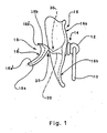
- the pacifier according to the invention is illustrated in the shape of a dummy generally comprising the following parts/portions: a non-compulsory handle ring 10 suspended for free rotation in a bearing piece 12 which is firmly connected to or formed integrally with, respectively, an attachment portion 14 firmly connected to a stop disc 16 incorporating two asymmetrical parts 16a and 16b extending in the continuation of each other, the longitudinal (vertical) central portion thereof extending irregularly, non-linearly between upper and lower end, referred to position of use, figure 2. Between the stop disc 16 and the bubble body 18, a transition and connection portion 20 is mounted, carrying the bubble body 18 at the free end thereof.
- the two longitudinal parts 16a and 16b constituting extensions of each other are approximately staggered in relation to each other.
- the lower stop disc part 16b will, with the arched surface facing towards the bubble body 18, apart from in the central portion at the transition and connection portion's 20 connection place on the stop disc 16, be spaced at a somewhat larger distance from an imaginary plane through the handle ring 10 suspended vertically from the piece.
- These mutually displaced stop disc parts 16a and 16b form suitable stop surfaces for the lips of the child, upper lip 22, figure 2, becoming resting supportingly against the stop disc part 16a, while lower lip 24 becomes resting supportingly against the stop disc part 16b.
- stop disc 16 has a concave curvature laterally.
- the intermediate transition and connection portion 20 is formed and dimensioned such that it exhibits a small thickness and a relatively large width, especially in the area within which the portion 20 will be situated in the mouth, between the front teeth 26 of the upper part of the mouth and the front teeth 28 in the lower part of the mouth, figure 2.
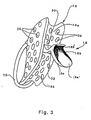
- the transition and connection portion 20 exhibits two oppositely directed, in longitudinal cross-sections notch-like grooves 30 and 32, respectively, see particularly figure 3.
- the bubble body 18 carried at the free end of the transition and connecting portion 20 has an outer face 18' facing away from the transition and connecting portion 20 as well as a concave angulation at the connecting place of the bubble body 18 at the free end of the portion 20, so that said outer face 18' which, possibly, has a lateral concave curvature, in respect of said connecting place, comprises a large, lower outer face portion 18a' passing into a far smaller, upper outer face portion 18b', the outer edge of the whole outer face 18' in side elevational view, figures 1 and 2, extending along an irregular curve.
- the lower part 18a of the bubble body 18 has an approximately even thickness from its outer, free end to the bubble body's 18 connecting place at the transition and connecting portion 20.
- the lower part 18a has approximately parallel faces. It has been found that such parallel faces are specially favourable for the positioning of the tongue within the mouth during sucking.
- transition and connecting portion's 20 outer portion close to the connecting place of the bubble body 18, i.e. in the area of said passage for the portion 20 between the teeth, may advantageously slope, preferably obliquely upwardly in the position of use, contributing to letting the tongue take a natural and convenient position in the mouth during sucking.
- the design and shape are especially advantageous with a view of avoiding crossbite.
- a disproportion arises between the tooth bow widths in the upper and lower jaw, often resulting in a crossbite.
- Crossbite resulting from the use of conventional pacifiers is often combined with a force-guidance of the lower jaw. This is a serious functional bite error requiring that a jaw orthopedical treatment is started at an early stage, in order to avoid a negative influence on the growth and development of the jaws.
- the general design and shape of the pacifier have been carried out with a view of avoiding the development of crossbite with a force-guidance of the lower jaw of children and, thus, primarily preventing that the pacifier presses the tongue down in the floor of the oral cavity, which i.a. may result in that the upper jaw's tooth bow becomes too narrow and the lower jaw's tooth bow too broad.
- the lower jaw is pressed out to one side.
- the pacifier according to the invention is designed and shaped such that crossbite with forced guiding of the lower jaw is prevented; this is achieved through the special shape, positioning and orientation of the bubble body within the mouth in relation to the tongue 34, figure 2, confer the unrestrained, natural position and condition of the tongue.
- Beneath the tongue, underlying salivary glands, frenum, etc., 34' are taking positions without restraint, substantially unaffected by the bubble body 18 of the pacifier.
- the pacifier prevents the tongue 34,34' from being pressed down in the floor of the oral cavity.
- the face 18a',18b' of the bubble body 18 which primarily comes into contact with the upper side of the tongue 34, figure 2, may according to figure 3 exhibit an approximately oval circumferential shape, possibly with a weak curvature laterally, at least across a longitudinal portion thereof.
- the bubble body 18, particularly the detailed design and shape of its outer face 18a',18b' will continuously be the subject matter of modifications and adaptations based on experiments and experiences.
- the bubble body 18 will have an asymmetrical plate-like shape in relation to its connection point in relation to the transition and connecting portion 20 at the adjacent axial end thereof.
- such an angled plate piece may have a weak concave curvature in at least one direction, possibly exhibiting a double curvature, i.e.
- the outer face 18b' of the bubble body 18 may, possibly, be omitted.
Landscapes
- Health & Medical Sciences (AREA)
- Pediatric Medicine (AREA)
- Life Sciences & Earth Sciences (AREA)
- Animal Behavior & Ethology (AREA)
- General Health & Medical Sciences (AREA)
- Public Health (AREA)
- Veterinary Medicine (AREA)
- Oral & Maxillofacial Surgery (AREA)
- Medical Preparation Storing Or Oral Administration Devices (AREA)
- Orthopedics, Nursing, And Contraception (AREA)
- Pharmaceuticals Containing Other Organic And Inorganic Compounds (AREA)
- Vending Machines For Individual Products (AREA)
- Macromonomer-Based Addition Polymer (AREA)
- External Artificial Organs (AREA)
- Solid-Sorbent Or Filter-Aiding Compositions (AREA)
- Control Of Driving Devices And Active Controlling Of Vehicle (AREA)
- Glass Compositions (AREA)
- Fats And Perfumes (AREA)
- Surgical Instruments (AREA)
- Acyclic And Carbocyclic Compounds In Medicinal Compositions (AREA)
Claims (10)
- Beruhigurigssauger mit wenigstens den folgenden Komponenten: ein Saugerkörper (18) für ein Kind um daran zu saugen, eine Anschlagscheibe (16), die eine Anschlagfläche gegen die Kinderlippen (22, 24) bildet und mit einem Übergangs- und Verbindungsbereich (20), der zwischen dem Saugerkörper (18) und der Anschlagfläche (60) angeordnet ist, welcher Saugerkörper (18) bezüglich seines Verbindungspunktes an einem Endbereich des Übergangs- Verbindungsbereichs (20) asymmetrisch ausgebildet ist, wobei der Saugerkörper (18) eine konkav gebogene äussere Fläche (18') aufweist, die im Gebrauch zum Mundinnehraum des Kindes gerichtet ist, so dass diese Fläche (18') einen Auflagebereich für einen gegenüberliegenden Bereich der Kinderzunge (34) bildet, wobei der Saugerkörper (18) zwei Saugerteile (18a, 18b) von unterschiedlicher Länge aufweist, die im Gebrauch einen oberen Saugerteil (18b) und einen unteren Saugerteil (18a) bilden, und wobei der untere Saugerteil (18a) nach unten absteigend und der obere Saugerteil (18b) nach oben ansteigend ist, wobei die genannte asymmetrische Form des Saugerkörpers (18) gemäss einer Seitenansicht gebildet wird, dadurch gekennzeichnet, dass der obere Saugerteil (18b) kürzer ist als der untere Saugerteil (18b) und dass der obere Saugerteil (18b) einen äusseren Flächenbereich (18b') und der untere Körperteil (18a) einen äusseren Flächenbereich (18a') aufweist, wobei zwischen diesen beiden Flächenbereichen ein Winkel gebildet wird und diese beiden Flächenbereiche (18a', 18b') zusammen die genannte konkav gebogene äussere Fläche (18') bilden, und dass die Anschlagscheibe (16) zwei längliche Anschlagscheibenbereiche (16a, 16b) bilden, die ineinander übergehen und im Gebrauch einen oberen Anschlagscheibenbereich (16a) und einen unteren Anschlagscheibenbereich (16b) bilden, wobei der obere Scheibenbereich (16a) für eine Anlage an die Oberlippe (22) des Kindes vorgesehen ist und der untere Scheibenbereich (16b) als Anlage gegen die Unterlippe (24) des Kindes vorgesehen ist und wobei die beiden länglichen Scheibenbereiche (16a, 16b) zueinander versetzt sind, und wobei die Oberfläche des unteren Scheibenbereichs (16b), welche dem Saugerkörper (18) gegenüber liegt, näher beim Saugerkörper (18) angeordnet ist als die entsprechende Oberfläche des unteren Scheibenbereichs (16a).
- Beruhigungssauger gemäss Anspruch 1, dadurch gekennzeichnet, dass das äussere freie Ende des längeren Saugerteils (18a) in grösserer axialer Distanz zum Verbindungspunkt am Endbereich des Übergangs- und Verbindungsbereichs (20) angeordnet ist, als das äussere freie Ende des kürzeren Saugerteils (18b).
- Beruhigungssauer nach Anspruch 1 oder 2, dadurch gekennzeichnet, dass die äussere Oberfläche des unteren Anschlagscheibenbereichs (16b), welche dem Saugerkörper (18) gegenüberliegt, mit einer konvexen Biegung über einen Teil der länglichen Erstreckung versehen ist, während die korrespondierende äussere Oberfläche des oberen Anschlagscheibenbereichs (16a) mit einer konkaven Biegung versehen ist, die sich über einen Teil der länglichen Erstreckung erstreckt.
- Beruhigungssauger nach Anspruch 3, dadurch gekennzeichnet, dass die genannte konvexe Biegung des unteren Anschlagscheibenbereichs (16b) geschlossen am ausgeprägtesten ist in einem Abstand von Verbindungspunkt der Anschlagscheibe (16) am benachbarten Endbereich des Übergangs- und Verbindungsbereichs (20), während die genannte konkave Biegung des oberen Anschlagscheibenbereichs (16a) am ausgeprägtesten ist in der Nachbarschaft des Verbindungspunktes der Anschlagscheibe (16) am benachbarten Endbereich des Übergangs- und Verbindungsbereichs (20).
- Beruhigungssauger nach einem der vorhergehenden Ansprüche, dadurch gekennzeichnet, dass die Anschlagscheibe (16) eine konkave seitliche Biegung auf der Oberfläche aufweist, die gegenüber dem Saugerkörper (18) angeordnet ist.
- Beruhigungssauger nach einem der vorhergehenden Ansprüche, dadurch gekennzeichnet, dass der genannte Übergangs- und Verbindungsbereich (20) eine kleine Dicke und eine grosse Breite aufweist, wobei sich die Dicken-Dimension aus einer Seitenansicht, und die Breite aus einer rechtwinklig dazu verlaufenden Ansicht ergibt.
- Beruhigungssauger nach Anspruch 6, dadurch gekennzeichnet, dass der Übergangs- und Verbindungsbereich (20) zwei Vertiefungen (30, 32) aufweist, die im Querschnitt gesehen rillenförmig sind und im Gebrauch eine obere Vertiefung (30) und eine untere Vertiefung (32) bilden, wobei die obere Vertiefung (30) nach oben offen und nach unten gerichtet ist, während die untere Vertiefung (32) nach unten offen und nach oben gerichtet ist, welche Vertiefungen (30, 32) Führungsmittel für Frontzähne (26, 28) bilden, und wobei die obere Vertiefung (30) in grösserem Abstand zum Verbindungspunkt des Übergangs- und Verbindungsbereichs (20) zum Saugerkörper (18) angeordnet ist, als die untere Vertiefung (32).
- Beruhigungssauger nach Anspruch 7, dadurch gekennzeichnet, dass die untere Vertiefung (32) bei oder in der unmittelbaren Nachbarschaft des Verbindungspunktes des Saugerkörpers (18) am benachbarten Endbereich des Übergangs- und Verbindungsbereichs (20) angeordnet ist.
- Beruhigungssauger nach einem der vorhergehenden Ansprüche, dadurch gekennzeichnet, dass wenigstens der Saugerkörper (18) und der Übergangs- und Verbindungsbereich (20) als Einheit aus dem gleichen Werkstoff gebildet ist.
- Beruhigungssauger nach einem der Ansprüche 6 bis 8, dadurch gekennzeichnet, dass der äussere axiale Endbereich des Übergangs- und Verbindungsbereichs (20), der benachbart zum Verbindungspunkt zum Saugerkörper (18) ist, im Gebrauch in einer Biegung nach oben verläuft, so dass der Anlageort zwischen Frontzähnen (26, 28) oder Zahnfleisch einen nach oben gerichteten Verlauf nimmt.
Applications Claiming Priority (3)
| Application Number | Priority Date | Filing Date | Title |
|---|---|---|---|
| NO962832A NO302926B1 (no) | 1996-07-05 | 1996-07-05 | Smokk, særlig av narresmokktype |
| NO962832 | 1996-07-05 | ||
| PCT/NO1997/000160 WO1998002132A1 (en) | 1996-07-05 | 1997-06-20 | Teat, in particular of the comforter type |
Publications (2)
| Publication Number | Publication Date |
|---|---|
| EP0959870A1 EP0959870A1 (de) | 1999-12-01 |
| EP0959870B1 true EP0959870B1 (de) | 2003-05-02 |
Family
ID=19899593
Family Applications (1)
| Application Number | Title | Priority Date | Filing Date |
|---|---|---|---|
| EP97927508A Expired - Lifetime EP0959870B1 (de) | 1996-07-05 | 1997-06-20 | Sauger, insbesondere beruhigungssauger |
Country Status (11)
| Country | Link |
|---|---|
| EP (1) | EP0959870B1 (de) |
| JP (1) | JP3844362B2 (de) |
| CN (1) | CN1142760C (de) |
| AT (1) | ATE238749T1 (de) |
| AU (1) | AU707566B2 (de) |
| DE (1) | DE69721573T2 (de) |
| DK (1) | DK0959870T3 (de) |
| ES (1) | ES2198574T3 (de) |
| NO (1) | NO302926B1 (de) |
| PL (1) | PL185336B1 (de) |
| WO (1) | WO1998002132A1 (de) |
Families Citing this family (9)
| Publication number | Priority date | Publication date | Assignee | Title |
|---|---|---|---|---|
| AU8858798A (en) * | 1997-07-23 | 1999-02-16 | Rolf Brockhaus | Pacifier |
| FR2792189B1 (fr) * | 1999-04-14 | 2001-10-12 | Louis Marie Dussere | Tetine ergonomique |
| DE10227787B4 (de) * | 2002-03-22 | 2006-02-23 | Novatex Gmbh | Sauger |
| DE102004031106B4 (de) * | 2004-06-28 | 2008-09-04 | Hagemann, Kai, Dr. | Beruhigungssauger |
| JP4597702B2 (ja) * | 2005-02-24 | 2010-12-15 | ピジョン株式会社 | 口唇閉鎖具 |
| BRPI0713166B8 (pt) | 2006-07-13 | 2021-06-22 | Mam Babyartikel | chupeta |
| AT510970B1 (de) | 2011-02-11 | 2012-08-15 | Mam Babyartikel | Verfahren zur herstellung eines schnullersaugers sowie schnullersauger |
| FR2972921B1 (fr) * | 2011-03-25 | 2016-05-13 | Iltet | Sucette orthodontique |
| WO2023221087A1 (zh) * | 2022-05-20 | 2023-11-23 | 林辅谊 | 防暴牙安抚用奶嘴及其奶瓶用奶嘴 |
Family Cites Families (4)
| Publication number | Priority date | Publication date | Assignee | Title |
|---|---|---|---|---|
| DE3840178A1 (de) * | 1988-11-29 | 1990-05-31 | Christoph Dr Herrmann | Sauger fuer mund- und kieferformzwecke |
| US4986751A (en) * | 1989-05-30 | 1991-01-22 | Bergersen Earl Olaf | Infant guidance pacifier appliance |
| US5133740A (en) * | 1990-12-24 | 1992-07-28 | Leon Kussick | Orthopedic pacifier |
| DE4318693B4 (de) * | 1993-06-04 | 2004-12-30 | Pick, Herbert, Dr. | Schnuller |
-
1996
- 1996-07-05 NO NO962832A patent/NO302926B1/no not_active IP Right Cessation
-
1997
- 1997-06-20 AT AT97927508T patent/ATE238749T1/de not_active IP Right Cessation
- 1997-06-20 AU AU31956/97A patent/AU707566B2/en not_active Ceased
- 1997-06-20 WO PCT/NO1997/000160 patent/WO1998002132A1/en not_active Ceased
- 1997-06-20 DE DE69721573T patent/DE69721573T2/de not_active Expired - Lifetime
- 1997-06-20 DK DK97927508T patent/DK0959870T3/da active
- 1997-06-20 CN CNB971961093A patent/CN1142760C/zh not_active Expired - Fee Related
- 1997-06-20 JP JP50543498A patent/JP3844362B2/ja not_active Expired - Fee Related
- 1997-06-20 ES ES97927508T patent/ES2198574T3/es not_active Expired - Lifetime
- 1997-06-20 EP EP97927508A patent/EP0959870B1/de not_active Expired - Lifetime
- 1997-06-20 PL PL97330999A patent/PL185336B1/pl not_active IP Right Cessation
Also Published As
| Publication number | Publication date |
|---|---|
| CN1244111A (zh) | 2000-02-09 |
| AU3195697A (en) | 1998-02-09 |
| JP3844362B2 (ja) | 2006-11-08 |
| WO1998002132A1 (en) | 1998-01-22 |
| EP0959870A1 (de) | 1999-12-01 |
| NO962832L (no) | 1998-01-06 |
| DE69721573D1 (de) | 2003-06-05 |
| NO302926B1 (no) | 1998-05-11 |
| ATE238749T1 (de) | 2003-05-15 |
| DK0959870T3 (da) | 2003-08-18 |
| AU707566B2 (en) | 1999-07-15 |
| JP2001505446A (ja) | 2001-04-24 |
| PL185336B1 (pl) | 2003-04-30 |
| NO962832D0 (no) | 1996-07-05 |
| CN1142760C (zh) | 2004-03-24 |
| ES2198574T3 (es) | 2004-02-01 |
| PL330999A1 (en) | 1999-06-21 |
| DE69721573T2 (de) | 2004-02-26 |
Similar Documents
| Publication | Publication Date | Title |
|---|---|---|
| US6080186A (en) | Teat, in particular of the comforter type | |
| AU2003216878C1 (en) | Pacifier | |
| EP2174638B1 (de) | Zahn-Beissvorrichtung | |
| CA2657551C (en) | Teeth-cleaning pacifier having a convex teat body | |
| EP1613260B1 (de) | Beruhigungssauger | |
| AU617694B2 (en) | Silencer | |
| US7975701B2 (en) | Appliance, system and method for correction habits of an oral cavity | |
| EP0959870B1 (de) | Sauger, insbesondere beruhigungssauger | |
| CN101119699A (zh) | 嘴唇闭合器 | |
| CZ2000703A3 (cs) | Ortodontické zařízení vhodné pro různé velikosti úst a zubů pro ortodontickou nápravu a další využití | |
| FI108276B (fi) | Hupitutti | |
| US10874593B2 (en) | Pacifier to train proper tongue position | |
| US3096761A (en) | Mouth protector | |
| CA2260027C (en) | Teat, in particular of the comforter type | |
| US20070016253A1 (en) | Primary dental teether | |
| US3638309A (en) | Artificial denture | |
| WO2002064079A1 (en) | Pacifier | |
| KR102832644B1 (ko) | 치아 교정용 근기능 개선 장치 | |
| KR100473989B1 (ko) | 유아용모조젖꼭지 | |
| EP2189146A1 (de) | Beruhigungsmittel für ältere Menschen | |
| JP6637751B2 (ja) | 小児用歯牙保護デバイス |
Legal Events
| Date | Code | Title | Description |
|---|---|---|---|
| PUAI | Public reference made under article 153(3) epc to a published international application that has entered the european phase |
Free format text: ORIGINAL CODE: 0009012 |
|
| 17P | Request for examination filed |
Effective date: 19990125 |
|
| AK | Designated contracting states |
Kind code of ref document: A1 Designated state(s): AT BE CH DE DK ES FI FR GB GR IE IT LI NL PT SE |
|
| 17Q | First examination report despatched |
Effective date: 20011119 |
|
| GRAH | Despatch of communication of intention to grant a patent |
Free format text: ORIGINAL CODE: EPIDOS IGRA |
|
| GRAH | Despatch of communication of intention to grant a patent |
Free format text: ORIGINAL CODE: EPIDOS IGRA |
|
| RTI1 | Title (correction) |
Free format text: PACIFIER, IN PARTICULAR OF THE COMFORTER TYPE |
|
| RTI1 | Title (correction) |
Free format text: PACIFIER, IN PARTICULAR OF THE COMFORTER TYPE |
|
| GRAH | Despatch of communication of intention to grant a patent |
Free format text: ORIGINAL CODE: EPIDOS IGRA |
|
| GRAA | (expected) grant |
Free format text: ORIGINAL CODE: 0009210 |
|
| RAP1 | Party data changed (applicant data changed or rights of an application transferred) |
Owner name: OEGAARD, BJOERN Owner name: PEDERSEN, TERJE S. |
|
| RIN1 | Information on inventor provided before grant (corrected) |
Inventor name: OEGAARD, BJOERN Inventor name: PEDERSEN, TERJE S. |
|
| AK | Designated contracting states |
Designated state(s): AT BE CH DE DK ES FI FR GB GR IE IT LI NL PT SE |
|
| PG25 | Lapsed in a contracting state [announced via postgrant information from national office to epo] |
Ref country code: NL Free format text: LAPSE BECAUSE OF FAILURE TO SUBMIT A TRANSLATION OF THE DESCRIPTION OR TO PAY THE FEE WITHIN THE PRESCRIBED TIME-LIMIT Effective date: 20030502 Ref country code: LI Free format text: LAPSE BECAUSE OF FAILURE TO SUBMIT A TRANSLATION OF THE DESCRIPTION OR TO PAY THE FEE WITHIN THE PRESCRIBED TIME-LIMIT Effective date: 20030502 Ref country code: IT Free format text: LAPSE BECAUSE OF FAILURE TO SUBMIT A TRANSLATION OF THE DESCRIPTION OR TO PAY THE FEE WITHIN THE PRESCRIBED TIME-LIMIT;WARNING: LAPSES OF ITALIAN PATENTS WITH EFFECTIVE DATE BEFORE 2007 MAY HAVE OCCURRED AT ANY TIME BEFORE 2007. THE CORRECT EFFECTIVE DATE MAY BE DIFFERENT FROM THE ONE RECORDED. Effective date: 20030502 Ref country code: FI Free format text: LAPSE BECAUSE OF FAILURE TO SUBMIT A TRANSLATION OF THE DESCRIPTION OR TO PAY THE FEE WITHIN THE PRESCRIBED TIME-LIMIT Effective date: 20030502 Ref country code: CH Free format text: LAPSE BECAUSE OF FAILURE TO SUBMIT A TRANSLATION OF THE DESCRIPTION OR TO PAY THE FEE WITHIN THE PRESCRIBED TIME-LIMIT Effective date: 20030502 Ref country code: BE Free format text: LAPSE BECAUSE OF FAILURE TO SUBMIT A TRANSLATION OF THE DESCRIPTION OR TO PAY THE FEE WITHIN THE PRESCRIBED TIME-LIMIT Effective date: 20030502 |
|
| REG | Reference to a national code |
Ref country code: GB Ref legal event code: FG4D |
|
| REG | Reference to a national code |
Ref country code: CH Ref legal event code: EP |
|
| REF | Corresponds to: |
Ref document number: 69721573 Country of ref document: DE Date of ref document: 20030605 Kind code of ref document: P |
|
| REG | Reference to a national code |
Ref country code: IE Ref legal event code: FG4D |
|
| PG25 | Lapsed in a contracting state [announced via postgrant information from national office to epo] |
Ref country code: GR Free format text: LAPSE BECAUSE OF FAILURE TO SUBMIT A TRANSLATION OF THE DESCRIPTION OR TO PAY THE FEE WITHIN THE PRESCRIBED TIME-LIMIT Effective date: 20030802 |
|
| PG25 | Lapsed in a contracting state [announced via postgrant information from national office to epo] |
Ref country code: PT Free format text: LAPSE BECAUSE OF FAILURE TO SUBMIT A TRANSLATION OF THE DESCRIPTION OR TO PAY THE FEE WITHIN THE PRESCRIBED TIME-LIMIT Effective date: 20030804 |
|
| REG | Reference to a national code |
Ref country code: SE Ref legal event code: TRGR |
|
| REG | Reference to a national code |
Ref country code: DK Ref legal event code: T3 |
|
| NLV1 | Nl: lapsed or annulled due to failure to fulfill the requirements of art. 29p and 29m of the patents act | ||
| REG | Reference to a national code |
Ref country code: CH Ref legal event code: PL |
|
| REG | Reference to a national code |
Ref country code: ES Ref legal event code: FG2A Ref document number: 2198574 Country of ref document: ES Kind code of ref document: T3 |
|
| ET | Fr: translation filed | ||
| PLBE | No opposition filed within time limit |
Free format text: ORIGINAL CODE: 0009261 |
|
| STAA | Information on the status of an ep patent application or granted ep patent |
Free format text: STATUS: NO OPPOSITION FILED WITHIN TIME LIMIT |
|
| 26N | No opposition filed |
Effective date: 20040203 |
|
| PGFP | Annual fee paid to national office [announced via postgrant information from national office to epo] |
Ref country code: IE Payment date: 20100615 Year of fee payment: 14 Ref country code: FR Payment date: 20100701 Year of fee payment: 14 Ref country code: ES Payment date: 20100517 Year of fee payment: 14 Ref country code: DK Payment date: 20100527 Year of fee payment: 14 |
|
| PGFP | Annual fee paid to national office [announced via postgrant information from national office to epo] |
Ref country code: AT Payment date: 20100528 Year of fee payment: 14 |
|
| PGFP | Annual fee paid to national office [announced via postgrant information from national office to epo] |
Ref country code: SE Payment date: 20100629 Year of fee payment: 14 Ref country code: DE Payment date: 20100823 Year of fee payment: 14 |
|
| PGFP | Annual fee paid to national office [announced via postgrant information from national office to epo] |
Ref country code: GB Payment date: 20110620 Year of fee payment: 15 |
|
| REG | Reference to a national code |
Ref country code: DK Ref legal event code: EBP |
|
| REG | Reference to a national code |
Ref country code: SE Ref legal event code: EUG |
|
| PG25 | Lapsed in a contracting state [announced via postgrant information from national office to epo] |
Ref country code: AT Free format text: LAPSE BECAUSE OF NON-PAYMENT OF DUE FEES Effective date: 20110620 |
|
| REG | Reference to a national code |
Ref country code: AT Ref legal event code: MM01 Ref document number: 238749 Country of ref document: AT Kind code of ref document: T Effective date: 20110620 |
|
| REG | Reference to a national code |
Ref country code: FR Ref legal event code: ST Effective date: 20120229 |
|
| REG | Reference to a national code |
Ref country code: IE Ref legal event code: MM4A |
|
| REG | Reference to a national code |
Ref country code: DE Ref legal event code: R119 Ref document number: 69721573 Country of ref document: DE Effective date: 20120103 |
|
| PG25 | Lapsed in a contracting state [announced via postgrant information from national office to epo] |
Ref country code: IE Free format text: LAPSE BECAUSE OF NON-PAYMENT OF DUE FEES Effective date: 20110620 Ref country code: FR Free format text: LAPSE BECAUSE OF NON-PAYMENT OF DUE FEES Effective date: 20110630 Ref country code: DE Free format text: LAPSE BECAUSE OF NON-PAYMENT OF DUE FEES Effective date: 20120103 |
|
| PG25 | Lapsed in a contracting state [announced via postgrant information from national office to epo] |
Ref country code: DK Free format text: LAPSE BECAUSE OF NON-PAYMENT OF DUE FEES Effective date: 20110630 |
|
| GBPC | Gb: european patent ceased through non-payment of renewal fee |
Effective date: 20120620 |
|
| PG25 | Lapsed in a contracting state [announced via postgrant information from national office to epo] |
Ref country code: GB Free format text: LAPSE BECAUSE OF NON-PAYMENT OF DUE FEES Effective date: 20120620 Ref country code: SE Free format text: LAPSE BECAUSE OF NON-PAYMENT OF DUE FEES Effective date: 20110621 |
|
| REG | Reference to a national code |
Ref country code: ES Ref legal event code: FD2A Effective date: 20130606 |
|
| PG25 | Lapsed in a contracting state [announced via postgrant information from national office to epo] |
Ref country code: ES Free format text: LAPSE BECAUSE OF NON-PAYMENT OF DUE FEES Effective date: 20110621 |