EP0960006B1 - Procede et dispositif pour couper des objets plats achemines en continu - Google Patents
Procede et dispositif pour couper des objets plats achemines en continu Download PDFInfo
- Publication number
- EP0960006B1 EP0960006B1 EP98900522A EP98900522A EP0960006B1 EP 0960006 B1 EP0960006 B1 EP 0960006B1 EP 98900522 A EP98900522 A EP 98900522A EP 98900522 A EP98900522 A EP 98900522A EP 0960006 B1 EP0960006 B1 EP 0960006B1
- Authority
- EP
- European Patent Office
- Prior art keywords
- cutting
- speed
- cutting edge
- rotation axis
- conveying direction
- Prior art date
- Legal status (The legal status is an assumption and is not a legal conclusion. Google has not performed a legal analysis and makes no representation as to the accuracy of the status listed.)
- Expired - Lifetime
Links
- 238000005520 cutting process Methods 0.000 title claims description 269
- 238000000034 method Methods 0.000 title claims description 31
- 238000009966 trimming Methods 0.000 claims description 9
- 239000000969 carrier Substances 0.000 claims description 3
- 239000000463 material Substances 0.000 claims description 3
- 230000015572 biosynthetic process Effects 0.000 claims 1
- 238000011144 upstream manufacturing Methods 0.000 claims 1
- 230000005484 gravity Effects 0.000 description 5
- 230000000694 effects Effects 0.000 description 4
- 239000010410 layer Substances 0.000 description 4
- 235000004522 Pentaglottis sempervirens Nutrition 0.000 description 1
- 230000001133 acceleration Effects 0.000 description 1
- 239000012790 adhesive layer Substances 0.000 description 1
- 230000002411 adverse Effects 0.000 description 1
- 230000007423 decrease Effects 0.000 description 1
- 230000003247 decreasing effect Effects 0.000 description 1
- 230000001419 dependent effect Effects 0.000 description 1
- 238000009795 derivation Methods 0.000 description 1
- 230000000368 destabilizing effect Effects 0.000 description 1
- 238000010586 diagram Methods 0.000 description 1
Images


Classifications
-
- B—PERFORMING OPERATIONS; TRANSPORTING
- B26—HAND CUTTING TOOLS; CUTTING; SEVERING
- B26D—CUTTING; DETAILS COMMON TO MACHINES FOR PERFORATING, PUNCHING, CUTTING-OUT, STAMPING-OUT OR SEVERING
- B26D11/00—Combinations of several similar cutting apparatus
-
- B—PERFORMING OPERATIONS; TRANSPORTING
- B26—HAND CUTTING TOOLS; CUTTING; SEVERING
- B26D—CUTTING; DETAILS COMMON TO MACHINES FOR PERFORATING, PUNCHING, CUTTING-OUT, STAMPING-OUT OR SEVERING
- B26D1/00—Cutting through work characterised by the nature or movement of the cutting member or particular materials not otherwise provided for; Apparatus or machines therefor; Cutting members therefor
- B26D1/01—Cutting through work characterised by the nature or movement of the cutting member or particular materials not otherwise provided for; Apparatus or machines therefor; Cutting members therefor involving a cutting member which does not travel with the work
- B26D1/12—Cutting through work characterised by the nature or movement of the cutting member or particular materials not otherwise provided for; Apparatus or machines therefor; Cutting members therefor involving a cutting member which does not travel with the work having a cutting member moving about an axis
- B26D1/25—Cutting through work characterised by the nature or movement of the cutting member or particular materials not otherwise provided for; Apparatus or machines therefor; Cutting members therefor involving a cutting member which does not travel with the work having a cutting member moving about an axis with a non-circular cutting member
- B26D1/26—Cutting through work characterised by the nature or movement of the cutting member or particular materials not otherwise provided for; Apparatus or machines therefor; Cutting members therefor involving a cutting member which does not travel with the work having a cutting member moving about an axis with a non-circular cutting member moving about an axis substantially perpendicular to the line of cut
- B26D1/28—Cutting through work characterised by the nature or movement of the cutting member or particular materials not otherwise provided for; Apparatus or machines therefor; Cutting members therefor involving a cutting member which does not travel with the work having a cutting member moving about an axis with a non-circular cutting member moving about an axis substantially perpendicular to the line of cut and rotating continuously in one direction during cutting
Definitions
- the invention relates to a method according to the preamble of the first independent Claim.
- the process is used for cutting continuously and flat objects conveyed parallel to their main surfaces along predetermined cutting lines that are parallel to the conveying direction run.
- the method is particularly suitable for cutting of flat objects that are difficult to cut because, for example, are easily deformable and / or several if necessary there are also easily deformable layers, which layers only stick little together. Multi-page printed products made of relatively thin Papers are such items.
- the invention further relates to a device according to the preamble of corresponding claim for performing the method.
- Cross-cutting devices transverse to their major surfaces continuously funded, flat objects are, for example, from the Publication EP-367715 (F271) discloses devices for cutting objects continuously conveyed parallel to their main surfaces, for example from publication US-3069952 or from publication EP-0698451. In the case of funding, they lie parallel to the main areas of the cutting objects the specified cutting lines transverse to the conveying direction, is the arrangement of the two cutting edges across the conveying direction align. Since a finite period of time is necessary for the cutting process it is also obvious for such a cut that for a high cutting accuracy the cutting device at least during the Cutting process with the object to be cut got to.
- the object of the invention is to demonstrate a method with the continuously, with a constant conveying speed and essentially Flat objects conveyed parallel to their main surfaces along predetermined cutting lines aligned parallel to the conveying direction are to be cut between two cutting edges, one first of the cutting edges in the support or conveying plane of one to be cut
- the object lies and the second cutting edge for the cutting process is moved past the first cutting edge and advantageously crosses with this.
- the cutting method according to the invention by appropriate guidance at least the second cutting edge Sufficient to very high cutting qualities even with low contact pressures can be reached.
- it should be possible to be difficult too cutting objects e.g.
- the invention is based on the knowledge that printed products that are made from consist of several pages, then with a slight pressure or even without to be pressed against a support surface with sufficient to very good cut quality can be cut if at any moment of Cutting process at least that point of the second cutting edge, involved in the cutting process (crossing point with the first Cutting edge or cutting point), a relative speed the object to be cut, which is as perpendicular as possible to the Support level or to the first cutting edge or to the main surfaces of the cutting object is directed. That means it is enough if only this cutting point on the second cutting edge is an absolute speed has, the component in the conveying direction as exactly as possible is as big as the conveying speed.
- At least the second, cutting edge moved against the support plane so matched to the continuous conveyance of the objects to be cut moves that too at least the cutting point of each cutting process
- Cutting edge has a speed whose component in the conveying direction is the same as the constant conveying speed.
- the holding devices have the function, the products to hold such that they are at the first cutting edge and advantageously rest on a bearing surface containing the first cutting edge.
- Such a movement of the second cutting edge is easiest can be realized by crossing them with the first cutting edge a constant swivel speed around one above the support level arranged, stationary pivot axis moved past the first cutting edge is, the pivot axis is perpendicular to that plane in the two cutting edges are arranged.
- the cutting speed that is, the speed, with which the cutting point on the main surface of the moving object depends on the swiveling speed and the position of the pivoted, second cutting edge relative to Pivot axis. This location can be freely selected within wide limits.
- the device according to the invention for carrying out those described above essentially consists of a pair of blades aligned in the conveying direction, each with a essential straight cutting edge.
- the first cutting edge is in the Support plane of the object to be cut arranged
- the second Cutting edge is about a swivel axis above the support level pivotable.
- the second cutting edge lies in a plane that is aligned perpendicular to the pivot axis.
- the first cutting edge arranged to be cut is sufficient, if it is stationary. But this cutting edge can also be moved such that the relative speed in the conveying direction between the first Cutting edge and object to be cut is minimized.
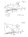
- FIG. 1 shows a simple diagram which can be used to explain a preferred embodiment of the method according to the invention.
- the figure shows a line with arrow F as the conveying direction of the objects to be cut, one of which is shown and labeled G.
- Line F simultaneously represents a section through the support or conveying plane for objects G to be cut and a first cutting edge SK 1 aligned in this supporting plane and parallel to the conveying direction.
- the figure also shows a second cutting edge SK 2 , which is about a stationary pivot axis M is pivotable relative to the first cutting edge SK 1 in a plane perpendicular to the pivot axis M and at a constant pivoting speed ⁇ .
- the second cutting edge SK 2 is crossed with the first cutting edge, that is to say in cutting engagement.
- the point S 1 of the cutting edge SK 2 is first in cutting engagement with the first cutting edge SK 1 , that is, S 1 is the cutting point.
- the cutting point moves to the left on both cutting edges.
- the cutting engagement ends at position SK 2 'of the second cutting edge when point S 2 (position S 2 ') forms the cutting point of the second cutting edge.
- the speed component v F in the conveying direction is therefore independent of the radius with which the cutting point moves around the swivel axis, i.e. it is constant at constant ⁇ during the entire cutting process and always the same as the tangential speed of a point that is at a radius with the angular speed ⁇ y rotates around M.
- the cutting edge SK 2 must be returned from its swivel position after cutting (SK 2 ') to the starting position (SK 2 ). This can be achieved either by swiveling in the opposite direction to swiveling for the cutting process or by rotating about the swiveling axis M in the same direction as the swiveling for the cutting process. Since the above explanations show that the swiveling speed ⁇ must be constant for the cutting process, the rotation variant is more advantageous, since a constant angular speed can be realized more easily for a rotation than for a cyclical swiveling back and forth.
- a cutting process according to FIG. 1 begins at the leading edge of the object G in the conveying direction and ends at its trailing edge.
- an object G can be completely cut in a single cutting process if its extent in the conveying direction is not greater than the distance between the points S 1 and S 2 'plus the distance which it is moved forward during the cutting process.
- the second cutting edge is advantageously designed in such a way that its start and end areas are not used for cutting an object, that is to say that the path S 1 -S 2 'is advantageously designed such that it is larger than the extent in the conveying direction of the object to be cut.
- FIG. 1 It can also be seen from FIG. 1 that the cutting angle (angle between the two cutting edges involved in the cutting process) decreases during the cutting process, the cutting speed decreasing with increasing initial cutting angle ⁇ . It can be seen from the above derivation that the cutting angle ⁇ has no influence on the speed component v F , that is to say that it can be freely selected, as required by the task.
- FIGS. 2 to 5 This is further illustrated by FIGS. 2 to 5, in which arrangements are shown which correspond to the arrangement according to FIG. 1 except for the initial cutting angle ( ⁇ .1 to ⁇ .4).
- the pivot position of the second cutting edge SK 2 at the beginning of the cutting process and SK 2 'at the end of the cutting process is again shown in each of FIGS. 2 to 5.
- FIG. 2 shows a larger initial cutting angle ⁇ .1 than the initial cutting angle ⁇ of FIG. 1. Since the initial cutting angle ⁇ .1 opens away from the pivot axis as in FIG. 1, the object G is cut from the leading edge as in FIG , Since the angle ⁇ .1 is larger than ⁇ (FIG. 1), the cutting speed is lower.
- Figure 3 shows an initial cutting angle ⁇ .2, which opens against the pivot axis M, whereby the cutting process begins at the trailing edge of the object G to be cut.
- the speed ratios are the same as in FIGS. 1 and 2.
- Figure 4 shows a special case, a second cutting edge SK 2 , which is arranged radially relative to the pivot axis M.
- the initial cutting angle ⁇ .3 is also open in such a case against the pivot axis M (cutting process begins at the trailing edge of the object G) and is equal to the angle whose sine y / r is 2 .
- the time span that is necessary for such a cut is theoretically zero and practically only dependent on the thickness (extension in the direction y) of the object G.
- the condition of Limitation of the relative speed to a component perpendicular to the main surfaces of an object G to be cut can be fulfilled.
- FIG. 6 shows an exemplary embodiment of the device according to the invention with a carrier 10, on which a plurality of blades 11 with second cutting edges SK 2 are arranged in a star shape and which is one by a distance y above the support plane of the objects G to be cut or above the first Cutting edge SK 1 arranged pivot axis M and is driven to rotate at a constant angular velocity ⁇ .
- the blades 11 are to be arranged such that the distance S 1 -S 2 'is at least as large as l minus the distance by which an object is transported forward during a cutting process (at least as large as l for short cutting times). If n (for example three) second cutting edges are provided, the corresponding blades are each offset by 360 ° / n (for example 120 °) in order to arrange the center of the carrier 10.
- FIG. 7 shows very schematically an exemplary embodiment of the device according to the invention with a rotating carrier 10 on which six blades 11 with second cutting edges SK 2 are arranged in a star shape such that the objects G fed in the conveying direction F are cut from their trailing edge, as is the case here has already been described in connection with FIGS. 3 and 4.
- FIGS. 6 and 7 show star-shaped carriers with three or six blades 11 with second cutting edges SK 2 .
- the number of blades 11 is to be matched to the blade arrangement (cutting angle) and to an easily realizable range of the rotational speed. As already mentioned in connection with FIG. 1, it is also possible to arrange only one blade with a second cutting edge on a corresponding rotating support.
- FIG. 8 shows two embodiments of devices according to the invention, which are designed in this way.
- FIG. 8 shows a conveying direction for objects G to be cut, again represented by an arrow F.
- the cutting area is shown schematically by the pivot axis M and by a pivotable, second cutting edge SK 2 .
- the arrow F represents, for example, a pair of conveyor belts are arranged in parallel and spaced from each other and the are driven synchronously. Between the conveyor belts represented by arrow F. brake cams 15 are moved. These brake cams 15 are, for example on an endless chain 17 running over two deflection wheels 16 arranged and moved such that they are in the cutting area over the The support level of the objects protrude and is slightly slower in the conveying direction move as the pair of conveyor belts. Through these brake cams are the objects fed on the conveyor belts before they are in the Reach the cutting area, lightly braked and precise for the cutting process clocked. During the cutting process, they guide those to be cut Items.
- a plurality of blades 18 with first cutting edges SK 1 can now also be arranged on the same chain 17.
- These blades are, for example, pivotably arranged on the chain and spaced from the brake cams in such a way that they can be positioned in the cutting area outside the conveyor belts.
- the blades 18 With a moving link 19, the blades 18 are guided at least in the cutting area such that the first cutting edges SK 1 are positioned in the support plane of the objects to be cut.
- first cutting edges SK 1 have the same speed in the conveying direction as the brake cams, that is to say also the same speed as the objects to be cut.
- an entire cutting device in the sense of a pair of scissors, which has a first and a second Has cutting edge on two blades pivotable relative to one another about a swivel axis, with which the objects to be cut are carried along. So that the condition of the relative speed of the second cutting edge, which is to be limited to a component perpendicular to the support plane, is fulfilled in such a case, the pivot axis must be arranged in the support plane.
- FIG. 9 shows a bird's eye view of an arrangement with three devices 30.1 to 30.3 according to the invention for three-sided trimming of printed products P with, for example, bound, stapled or glued back R.
- the printed products are conveyed in succession in a first conveying direction F.1 parallel to their back R and trimmed by means of the first cutting device 30.1 on its front edge opposite the back R.
- the printed products are deflected in a manner known per se, without changing their spatial position, in such a way that they are conveyed further in a second conveying direction F.2 transversely to their back R.
- the foot and head edges of the printed products are simultaneously cut by cutting devices 30.2 and 30.3 arranged opposite one another.
- FIG. 10 shows a schematic, three-dimensional representation of a further arrangement in which booklet-like products P with a spine R are trimmed on three edges with the aid of two devices 30.2 and 30.3 according to the invention, which are arranged coaxially and are coaxially arranged and driven simultaneously.
- the two cutting devices 30.2 and 30.3 each have, for example, four blades 11 rotating about a pivot axis M with first cutting edges SK 1 .
- the products P are in a feed conveyor F.3 between the two Devices 30.2 and 30.3 supplied, the back R of the products P is aligned in the feed direction F.3.
- the Both cutting devices become the product edge parallel to the back R trimmed from one (30.2) of the two cutting devices.
- the products are then rotated through 90 ° about their own axis, that the back is directed perpendicular to the conveying direction F.3, and the Product flow is turned 180 ° against devices 30.2 and 30.3 turned back, such that the products, for example, with a leading Back with a further feed direction F.4 between the Devices 30.2 and 30.3 are promoted.
- This second Passage between devices 30.2 and 30.3 make the two perpendicular product edges aligned to the back R simultaneously from the two Devices 30.2 and 30.3 trimmed.
- the products are, for example, without change their spatial position, deflected by 90 ° and in a direction of conveyance F.5 promoted.
- the cutting arrangement is reversed relative to the force of gravity in relation to all the variants described above.
- the first cutting edge (not shown in FIG. 10) is not arranged below the products P (in the support plane of the products) but above the products and that the second cutting edges SK 2 are not moved from top to bottom for the cutting engagement but from bottom to top.
- Cutting devices according to the invention are not only as in FIGS. 9 and 10 for trimming printed products or other objects applicable, but also to print products (double benefit) or cut other objects into two parts to be used.
- the cutting method and devices according to the invention are not only applicable for cutting individual objects which are spaced apart and conveyed one behind the other. They can also be used for the longitudinal cutting or lateral cutting of streams of scale from overlapping conveyed flat objects or from quasi endless, continuously conveyed material webs. For such cases, the condition for the distance x between the objects to be cut is eliminated and the condition for the rotational speed ⁇ is that n times the cutting length (S 1 -S 2 ', Figure 1) must not be less than the material feed during one Rotation of the carrier with the n star-shaped blades with second cutting edges.
Landscapes
- Life Sciences & Earth Sciences (AREA)
- Forests & Forestry (AREA)
- Engineering & Computer Science (AREA)
- Mechanical Engineering (AREA)
- Control Of Cutting Processes (AREA)
- Details Of Cutting Devices (AREA)
- Auxiliary Devices For And Details Of Packaging Control (AREA)
Claims (14)
- Procédé pour la découpe d'objets plats (G) pendant un transport en continu dans un sens de transport (F) parallèle aux surfaces principales des objets et à une vitesse de transport constante vG, dans lequel les objets (G) sont coupés le long d'une ligne de coupe parallèle au sens de transport (F) entre un premier bord de coupe rectiligne et un second (SK1 et SK2), le premier bord de coupe (SK1) étant positionné dans un plan dans lequel les objets à couper (G) reposent par une surface principale, les bords de coupe (SK1 et SK2) étant déplacés l'un sur l'autre pour une opération de coupe de telle sorte qu 'ils se croisent en un point de coupe et que le point de coupe soit déplacé le long de la ligne de coupe par-dessus une surface principale de l'objet à couper, et le second bord de coupe (SK2) au moins étant déplacé de telle sorte que pendant toute l'opération de coupe, le point de coupe de ce second bord de coupe (SK2) au moins présente une composante de vitesse perpendiculairement au plan d'appui et une composante de vitesse (vF) dans le sens de transport (F), de telle sorte que la composante de vitesse (vF) soit égale dans le sens du transport à la vitesse de transport constante (vG), caractérisé en ce que le second bord de coupe (SK2) pivote pour l'opération de coupe à une vitesse de pivotement constante (ω) autour d'un axe de pivotement (M) stationnaire disposé par rapport au plan dans lequel repose le produit à couper, la vitesse de coupe (ω) et la distance (y) entre ledit plan et l'axe de pivotement (M) étant ajustées l'une à l'autre de telle sorte que la composante de vitesse (vF) de chaque point du second bord de coupe (SK2) qui est le point de coupe à un moment donné soit égale à la vitesse de transport (vG).
- Procédé selon la revendication 1, caractérisé en ce que le premier bord de coupe (SK1) est lui aussi déplacé de telle sorte qu'il présente une composante de vitesse dans le sens de transport (F) égale à la vitesse de transport (vG).
- Procédé selon la revendication 1 ou 2, caractérisé en ce que le second bord de coupe (SK2) pivote pour revenir ou effectue une rotation autour de l'axe de pivotement (M) entre deux opérations de coupe.
- Procédé selon la revendication 1 ou 2, caractérisé en ce qu'un certain nombre (n) de seconds bords de coupe (SK2) est disposé dans un plan perpendiculaire à l'axe de pivotement (M) et réparti à intervalles réguliers autour de celui-ci, et en ce que la disposition de seconds bords de coupe (SK2) effectue une rotation autour de l'axe de pivotement (M) de telle sorte que les seconds bords de coupe (SK2) passent l'un après l'autre devant le premier bord de coupe (SK1) pour des opérations de coupe successives.
- Procédé selon l'une ou l'ensemble des revendications 1 à 4, caractérisé en ce que les premier et second bords de coupe (SK1 et SK2) forment pendant l'opération de coupe un angle de coupe (β, β.1) qui s'ouvre à l'opposé de l'axe de pivotement (M) et en ce que l'opération de coupe commence sur le bord avant de l'objet (G).
- Procédé selon l'une ou l'ensemble des revendications 1 à 4, caractérisé en ce que les premier et second bords de coupe (SK1 et SK2) forment pendant l'opération de coupe un angle de coupe (β.2, β.3) qui s'ouvre vers l'axe de pivotement (M) et en ce que l'opération de coupe commence sur le bord arrière de l'objet (G).
- Procédé selon l'une ou l'ensemble des revendications 1 à 6, caractérisé en ce que les objets (G) à couper sont freinés ou accélérés et rythmés avant l'opération de coupe par des cames de freinage (15) ou des cames d'accélération.
- Dispositif pour la mise en oeuvre du procédé selon la revendication 1, servant à la découpe d'objets (G) transportés en continu parallèlement à leurs surfaces principales à une vitesse de transport (vG) constante dans un sens de transport (F) et coupés le long de lignes de coupe parallèles au sens de transport (F), lequel dispositif présente un premier bord de coupe (SK1) rectiligne disposé dans un plan sur lequel reposent les objets (G) à couper et parallèle au sens de transport (F) et un second bord de coupe (SK2) également rectiligne et pouvant être déplacé devant le premier bord de coupe (SK1) pour une opération de coupe, une lame (11) portant le second bord de coupe (SK2) étant disposée de façon pivotante sur un axe de pivotement (M) disposé par rapport audit plan sur lequel reposent les objets à couper et pouvant pivoter à une vitesse de pivotement (ω) constante, caractérisé en ce que l'axe de pivotement (M) est disposé à une certaine distance (y) dudit plan et la distance (y) et la vitesse de pivotement (ω) peuvent être adaptées l'une à l'autre de manière à remplir la condition 2πy × ω = vG.
- Dispositif selon la revendication 8, caractérisé en ce qu'il est prévu sur un support (10) plusieurs lames (11) avec des seconds bords de coupe (SK2) disposées en étoile dans un plan perpendiculaire à l'axe de pivotement (M), le support (10) étant en liaison de travail avec un entraínement de telle sorte qu'il puisse être entraíné en rotation à la vitesse de pivotement (ω) autour de l'axe de pivotement (M).
- Dispositif selon la revendication 8 ou 9, caractérisé en ce qu'une lame (18) portant le premier bord de coupe (SK1) est disposée de manière à pouvoir se déplacer dans le sens de transport (F) et à la vitesse de transport (vG).
- Mise en oeuvre du procédé selon la revendication 1 pour couper ou recouper des produits imprimés (P) transportés séparément les uns derrière les autres ou en formation en écailles.
- Mise en oeuvre selon la revendication 11, caractérisée en ce que les produits imprimés (P) transportés séparément les uns derrière les autres sont transportés parallèlement à leurs dos (R) et coupés sur leur bord avant, en ce que les produits imprimés (P) sont ensuite déviés à 90° sans que leur position dans l'espace soit modifiée, et en ce que leurs bords de pied et de tête sont ensuite coupés simultanément.
- Utilisation selon la revendication 11, caractérisée en ce qu'il est prévu deux supports rotatifs disposés de manière coaxiale sur un même axe de pivotement (M) et pouvant être entraínés simultanément, qui portent des lames munies de seconds bords de coupe (SK2), et en ce que les produits imprimés (P) transportés séparément les uns derrière les autres sont coupés pendant un premier et un second passage entre les supports, les produits étant tournés de 90° sur leur propre axe entre les deux passages et déviés de telle sorte que le premier passage se produit sur un côté de l'axe de pivotement (M) commun et le deuxième passage sur le côté opposé de l'axe de pivotement.
- Mise en oeuvre du procédé selon la revendication 1 pour la découpe longitudinale ou la recoupe latérale de lés de matériau quasiment sans fin.
Applications Claiming Priority (3)
| Application Number | Priority Date | Filing Date | Title |
|---|---|---|---|
| CH21597 | 1997-01-30 | ||
| CH21597 | 1997-01-30 | ||
| PCT/CH1998/000031 WO1998033630A1 (fr) | 1997-01-30 | 1998-01-28 | Procede et dispositif pour couper des objets plats achemines en continu |
Publications (2)
| Publication Number | Publication Date |
|---|---|
| EP0960006A1 EP0960006A1 (fr) | 1999-12-01 |
| EP0960006B1 true EP0960006B1 (fr) | 2002-04-17 |
Family
ID=4181900
Family Applications (1)
| Application Number | Title | Priority Date | Filing Date |
|---|---|---|---|
| EP98900522A Expired - Lifetime EP0960006B1 (fr) | 1997-01-30 | 1998-01-28 | Procede et dispositif pour couper des objets plats achemines en continu |
Country Status (7)
| Country | Link |
|---|---|
| EP (1) | EP0960006B1 (fr) |
| JP (1) | JP4077884B2 (fr) |
| AU (1) | AU739661B2 (fr) |
| CA (1) | CA2279866C (fr) |
| DE (1) | DE59803847D1 (fr) |
| DK (1) | DK0960006T3 (fr) |
| WO (1) | WO1998033630A1 (fr) |
Families Citing this family (1)
| Publication number | Priority date | Publication date | Assignee | Title |
|---|---|---|---|---|
| CA2636961A1 (fr) | 2007-07-11 | 2009-01-11 | Ferag Ag | Procede et dispositif de separation de voiles transportes en continu |
Family Cites Families (6)
| Publication number | Priority date | Publication date | Assignee | Title |
|---|---|---|---|---|
| US1642081A (en) * | 1925-09-04 | 1927-09-13 | Dahlberg & Company Inc | Apparatus for slitting continuously-moving material |
| US3153964A (en) * | 1960-05-26 | 1964-10-27 | Sun Printers Ltd | Production of magazines, pamphlets and the like |
| GB932281A (en) * | 1961-05-19 | 1963-07-24 | Mueller Hans | Cutter machine for paper |
| DE1258826B (de) * | 1966-11-07 | 1968-01-18 | Leipziger Buchbindereimaschine | Fliessschneider |
| DE2517121A1 (de) * | 1975-04-18 | 1976-10-28 | Helga Schaefferling Fa | Schneidvorrichtung bestehend aus rund- und langmesser |
| CA1330033C (fr) * | 1988-10-31 | 1994-06-07 | Walter Reist | Methode et appareil de coupe de produits imprimes |
-
1998
- 1998-01-28 EP EP98900522A patent/EP0960006B1/fr not_active Expired - Lifetime
- 1998-01-28 WO PCT/CH1998/000031 patent/WO1998033630A1/fr not_active Ceased
- 1998-01-28 CA CA002279866A patent/CA2279866C/fr not_active Expired - Fee Related
- 1998-01-28 JP JP53241898A patent/JP4077884B2/ja not_active Expired - Fee Related
- 1998-01-28 AU AU55475/98A patent/AU739661B2/en not_active Ceased
- 1998-01-28 DK DK98900522T patent/DK0960006T3/da active
- 1998-01-28 DE DE59803847T patent/DE59803847D1/de not_active Expired - Lifetime
Also Published As
| Publication number | Publication date |
|---|---|
| DK0960006T3 (da) | 2002-08-12 |
| JP4077884B2 (ja) | 2008-04-23 |
| DE59803847D1 (de) | 2002-05-23 |
| WO1998033630A1 (fr) | 1998-08-06 |
| CA2279866C (fr) | 2006-05-23 |
| CA2279866A1 (fr) | 1998-08-06 |
| AU739661B2 (en) | 2001-10-18 |
| AU5547598A (en) | 1998-08-25 |
| JP2001509742A (ja) | 2001-07-24 |
| EP0960006A1 (fr) | 1999-12-01 |
Similar Documents
| Publication | Publication Date | Title |
|---|---|---|
| DE69817499T2 (de) | Vorrichtung zum Transport von kontinuierlichen Bahnen aus langgestrecktem Material | |
| EP0367715B1 (fr) | Méthode et dispositif pour rogner des signatures | |
| DE2248683B2 (de) | Vorrichtung zum Querschneiden einer kontinuierlich angeförderten Materialbahn | |
| EP1810942B1 (fr) | Procédé de raccordement de bandes de matériau et dispositif de raccordement | |
| DE2334072A1 (de) | Verfahren und vorrichtung zum zuschneiden von bogenmaterial | |
| DE19703130C2 (de) | Einrichtung zum Auslenken von Signaturen mittels rotierender Flächen | |
| EP0278120B1 (fr) | Plieuse en accordéon | |
| DE1532091C3 (de) | Vorrichtung zum Zerschneiden einer fortlaufenden Bahn aus Tabak oder dgl | |
| DE10356037A1 (de) | Schneid-Vorrichtung | |
| EP1234790B1 (fr) | Dispositif pour transférer des objets plats alimentés seriellement à une section de déchargement | |
| DE60116464T2 (de) | Vorrichtung und Verfahren zum Schneiden von Folien, insbesondere für automatische Verpackungsanlagen | |
| EP2396227B1 (fr) | Dispositif de coupe et de separation | |
| DE4425042B4 (de) | Mitnehmer mit Schnellbefestigung | |
| DE2732837C2 (fr) | ||
| DE102009026113A1 (de) | Schneidscheibe, Schneidvorrichtung und Verfahren zum Vereinzeln von Gebindeeinheiten | |
| DE19638307B4 (de) | Verfahren zum Schneiden von kontinuierlich geförderten, flächigen Produkten aus Papier oder ähnlichen Materialien | |
| EP0960006B1 (fr) | Procede et dispositif pour couper des objets plats achemines en continu | |
| DE19927920A1 (de) | Schneideinrichtung im Falzapparat einer Rotationsdruckmaschine und Falzapparat mit einer solchen Schneideinrichtung | |
| EP4133942B1 (fr) | Paire d'éléments déplaceurs | |
| DE10209190B4 (de) | Schneidvorrichtung zum Querschneiden wenigstens einer Materialbahn | |
| WO2007045105A1 (fr) | Systeme de transport | |
| EP0890514B1 (fr) | Procédé pour fabriquer une bande en feuille pour un emballage en matériau pliant, et dispositif pour sa mise en oeuvre | |
| DE4418359A1 (de) | Verfahren und Vorrichtung zum Ausrichten von Stückgut | |
| DE102009008936A1 (de) | Schneid- und Spreizvorrichtung | |
| EP2388114B1 (fr) | Dispositif de perforation ou coupe transversale de bandes de matériau déroulantes |
Legal Events
| Date | Code | Title | Description |
|---|---|---|---|
| PUAI | Public reference made under article 153(3) epc to a published international application that has entered the european phase |
Free format text: ORIGINAL CODE: 0009012 |
|
| 17P | Request for examination filed |
Effective date: 19990724 |
|
| AK | Designated contracting states |
Kind code of ref document: A1 Designated state(s): BE CH DE DK FI FR GB IT LI NL SE |
|
| GRAG | Despatch of communication of intention to grant |
Free format text: ORIGINAL CODE: EPIDOS AGRA |
|
| 17Q | First examination report despatched |
Effective date: 20010719 |
|
| GRAG | Despatch of communication of intention to grant |
Free format text: ORIGINAL CODE: EPIDOS AGRA |
|
| GRAH | Despatch of communication of intention to grant a patent |
Free format text: ORIGINAL CODE: EPIDOS IGRA |
|
| GRAH | Despatch of communication of intention to grant a patent |
Free format text: ORIGINAL CODE: EPIDOS IGRA |
|
| REG | Reference to a national code |
Ref country code: GB Ref legal event code: IF02 |
|
| GRAA | (expected) grant |
Free format text: ORIGINAL CODE: 0009210 |
|
| AK | Designated contracting states |
Kind code of ref document: B1 Designated state(s): BE CH DE DK FI FR GB IT LI NL SE |
|
| REG | Reference to a national code |
Ref country code: CH Ref legal event code: EP |
|
| REF | Corresponds to: |
Ref document number: 59803847 Country of ref document: DE Date of ref document: 20020523 |
|
| REG | Reference to a national code |
Ref country code: CH Ref legal event code: NV Representative=s name: FREI PATENTANWALTSBUERO |
|
| GBT | Gb: translation of ep patent filed (gb section 77(6)(a)/1977) |
Effective date: 20020710 |
|
| REG | Reference to a national code |
Ref country code: DK Ref legal event code: T3 |
|
| ET | Fr: translation filed | ||
| PLBE | No opposition filed within time limit |
Free format text: ORIGINAL CODE: 0009261 |
|
| STAA | Information on the status of an ep patent application or granted ep patent |
Free format text: STATUS: NO OPPOSITION FILED WITHIN TIME LIMIT |
|
| 26N | No opposition filed |
Effective date: 20030120 |
|
| REG | Reference to a national code |
Ref country code: CH Ref legal event code: PFA Owner name: FERAG AG Free format text: FERAG AG#ZUERICHSTRASSE 74#8340 HINWIL (CH) -TRANSFER TO- FERAG AG#PATENTABTEILUNG Z. H. MARKUS FELIX ZUERICHSTRASSE 74#8340 HINWIL (CH) |
|
| PGFP | Annual fee paid to national office [announced via postgrant information from national office to epo] |
Ref country code: FI Payment date: 20080115 Year of fee payment: 11 |
|
| PGFP | Annual fee paid to national office [announced via postgrant information from national office to epo] |
Ref country code: FR Payment date: 20080111 Year of fee payment: 11 |
|
| PGFP | Annual fee paid to national office [announced via postgrant information from national office to epo] |
Ref country code: BE Payment date: 20080304 Year of fee payment: 11 |
|
| PGFP | Annual fee paid to national office [announced via postgrant information from national office to epo] |
Ref country code: GB Payment date: 20090122 Year of fee payment: 12 |
|
| PG25 | Lapsed in a contracting state [announced via postgrant information from national office to epo] |
Ref country code: FI Free format text: LAPSE BECAUSE OF NON-PAYMENT OF DUE FEES Effective date: 20090128 |
|
| REG | Reference to a national code |
Ref country code: FR Ref legal event code: ST Effective date: 20091030 |
|
| PG25 | Lapsed in a contracting state [announced via postgrant information from national office to epo] |
Ref country code: BE Free format text: LAPSE BECAUSE OF NON-PAYMENT OF DUE FEES Effective date: 20090131 |
|
| PG25 | Lapsed in a contracting state [announced via postgrant information from national office to epo] |
Ref country code: FR Free format text: LAPSE BECAUSE OF NON-PAYMENT OF DUE FEES Effective date: 20090202 |
|
| GBPC | Gb: european patent ceased through non-payment of renewal fee |
Effective date: 20100128 |
|
| PG25 | Lapsed in a contracting state [announced via postgrant information from national office to epo] |
Ref country code: GB Free format text: LAPSE BECAUSE OF NON-PAYMENT OF DUE FEES Effective date: 20100128 |
|
| PGFP | Annual fee paid to national office [announced via postgrant information from national office to epo] |
Ref country code: DK Payment date: 20110112 Year of fee payment: 14 |
|
| PGFP | Annual fee paid to national office [announced via postgrant information from national office to epo] |
Ref country code: SE Payment date: 20110113 Year of fee payment: 14 Ref country code: IT Payment date: 20110125 Year of fee payment: 14 Ref country code: NL Payment date: 20110117 Year of fee payment: 14 |
|
| PGFP | Annual fee paid to national office [announced via postgrant information from national office to epo] |
Ref country code: CH Payment date: 20120118 Year of fee payment: 15 |
|
| REG | Reference to a national code |
Ref country code: NL Ref legal event code: V1 Effective date: 20120801 |
|
| REG | Reference to a national code |
Ref country code: SE Ref legal event code: EUG |
|
| REG | Reference to a national code |
Ref country code: DK Ref legal event code: EBP |
|
| PG25 | Lapsed in a contracting state [announced via postgrant information from national office to epo] |
Ref country code: SE Free format text: LAPSE BECAUSE OF NON-PAYMENT OF DUE FEES Effective date: 20120129 |
|
| PG25 | Lapsed in a contracting state [announced via postgrant information from national office to epo] |
Ref country code: IT Free format text: LAPSE BECAUSE OF NON-PAYMENT OF DUE FEES Effective date: 20120128 |
|
| PG25 | Lapsed in a contracting state [announced via postgrant information from national office to epo] |
Ref country code: NL Free format text: LAPSE BECAUSE OF NON-PAYMENT OF DUE FEES Effective date: 20120801 Ref country code: DK Free format text: LAPSE BECAUSE OF NON-PAYMENT OF DUE FEES Effective date: 20120131 |
|
| PGFP | Annual fee paid to national office [announced via postgrant information from national office to epo] |
Ref country code: DE Payment date: 20130122 Year of fee payment: 16 |
|
| REG | Reference to a national code |
Ref country code: CH Ref legal event code: PL |
|
| PG25 | Lapsed in a contracting state [announced via postgrant information from national office to epo] |
Ref country code: CH Free format text: LAPSE BECAUSE OF NON-PAYMENT OF DUE FEES Effective date: 20130131 Ref country code: LI Free format text: LAPSE BECAUSE OF NON-PAYMENT OF DUE FEES Effective date: 20130131 |
|
| REG | Reference to a national code |
Ref country code: DE Ref legal event code: R119 Ref document number: 59803847 Country of ref document: DE |
|
| REG | Reference to a national code |
Ref country code: DE Ref legal event code: R119 Ref document number: 59803847 Country of ref document: DE Effective date: 20140801 |
|
| PG25 | Lapsed in a contracting state [announced via postgrant information from national office to epo] |
Ref country code: DE Free format text: LAPSE BECAUSE OF NON-PAYMENT OF DUE FEES Effective date: 20140801 |