EP0960017B1 - Procede pour faire fonctionner une presse electrique - Google Patents
Procede pour faire fonctionner une presse electrique Download PDFInfo
- Publication number
- EP0960017B1 EP0960017B1 EP98907927A EP98907927A EP0960017B1 EP 0960017 B1 EP0960017 B1 EP 0960017B1 EP 98907927 A EP98907927 A EP 98907927A EP 98907927 A EP98907927 A EP 98907927A EP 0960017 B1 EP0960017 B1 EP 0960017B1
- Authority
- EP
- European Patent Office
- Prior art keywords
- press ram
- compressive force
- pressing
- workpieces
- press
- Prior art date
- Legal status (The legal status is an assumption and is not a legal conclusion. Google has not performed a legal analysis and makes no representation as to the accuracy of the status listed.)
- Expired - Lifetime
Links
- 238000000034 method Methods 0.000 title claims abstract description 65
- 238000006073 displacement reaction Methods 0.000 claims abstract description 13
- 238000012545 processing Methods 0.000 claims description 9
- 238000012544 monitoring process Methods 0.000 claims description 4
- 238000000418 atomic force spectrum Methods 0.000 claims description 2
- 230000006378 damage Effects 0.000 description 4
- 230000001419 dependent effect Effects 0.000 description 3
- 230000007423 decrease Effects 0.000 description 2
- 238000012935 Averaging Methods 0.000 description 1
- 239000000853 adhesive Substances 0.000 description 1
- 230000001070 adhesive effect Effects 0.000 description 1
- 238000001514 detection method Methods 0.000 description 1
- 238000010586 diagram Methods 0.000 description 1
- 230000000694 effects Effects 0.000 description 1
- 238000003780 insertion Methods 0.000 description 1
- 230000037431 insertion Effects 0.000 description 1
- 238000005259 measurement Methods 0.000 description 1
- 230000002028 premature Effects 0.000 description 1
- 238000003908 quality control method Methods 0.000 description 1
- 230000003068 static effect Effects 0.000 description 1
- 238000012360 testing method Methods 0.000 description 1
Images

Classifications
-
- B—PERFORMING OPERATIONS; TRANSPORTING
- B30—PRESSES
- B30B—PRESSES IN GENERAL
- B30B15/00—Details of, or accessories for, presses; Auxiliary measures in connection with pressing
- B30B15/0094—Press load monitoring means
-
- B—PERFORMING OPERATIONS; TRANSPORTING
- B30—PRESSES
- B30B—PRESSES IN GENERAL
- B30B15/00—Details of, or accessories for, presses; Auxiliary measures in connection with pressing
- B30B15/14—Control arrangements for mechanically-driven presses
Definitions
- the known method is carried out on an electric press, the one driven by an electric motor spindle drive includes.
- the threaded spindle of the spindle drive is rotatable, however axially immovable while the spindle nut non-rotatable, but axially displaceable and with the Press ram is connected.
- the electric press has displacement transducers and force transducers the course of the pressing force over the path of the press ram during its working stroke and to a controller to report the working stroke based on this information controls.
- the press ram At the beginning of a pressing process, the press ram is in its Starting position moved above the workpiece and then lowered onto the workpiece or parts to be machined. While this lowering, the pressing force is measured and based on a Increase in this pressing force recognized that the pressing process begins, whereupon the lowering speed of the press ram is reduced becomes.
- the press ram becomes further lowered, the applied pressing force thereupon is monitored whether it remains constant during the pressing process. Furthermore, the path of the press ram continues to be monitored, to reach a joining position called there end position to recognize in which the press ram is not essentially further lowered. When this end position has been reached, the press ram retracted.
- this object is achieved according to the invention solved in that depending on the course the pressing force over the path of the press ram parameters dynamically be adapted to a successful course and / or Show completion of the pressing process.
- the inventors of the present application have recognized that that the high committee in the known method in particular is due to the fact that the beginning of the pressing process is recorded dynamically, but not the completion of the pressing process. In the prior art, a fixed end position is specified here reaching or not reaching about the success of the pressing process decides. Furthermore, during the pressing process required a constant pressing force, with a deviation of this constant pressing force also counted as a committee becomes.
- the new process now makes intelligent assembly also possible of coarser tolerated workpieces, because the for the result of the pressing process are decisive parameters the course of the pressing force during the working stroke of the press ram dynamically derived and adjusted. Based on this Parameters can then be a after a pressing process Statement can be made as to whether the pressing process is successful was and corresponds to specified test values.
- the advantage here is that in addition to or instead of the rough Adjustment of the end position depending on the start of the press the direct joining point is recognized at which e.g. if available of two workpieces that were pressed onto a block.
- Dependent on The joining or end position can vary from the tolerances of the workpieces differ with different workpieces, so that the mere determination of the end position from the start of the press is not is as reliable as deriving the joining position from the strong increase in pressing force.
- the Change of the pressing force over the way or also over time be monitored so that by evaluating this slope of the Joining point is recognized in real time.
- the advantage here is that not only the joining position itself but also the one to be applied in the joining position Press force dynamically depending on the tolerances of the Workpieces is adjusted.
- Press force dynamically depending on the tolerances of the Workpieces is adjusted.
- a very high pressing force is already required to Pressing workpieces onto block in the joining position.
- the pressing process is dependent on the Change in slope dynamically ended in the course of the pressing force, as soon as the workpieces have reached the joining position.
- the monitoring window is dependent from the start of the press only have to be moved so that differently tolerated parts can be detected.
- the advantage here is that the required pressing force can be determined and specified in a simple and very precise manner, because not only the working stroke, i.e. the path of the press ram but also in particular in the Allows the pressing position to be adjusted by hand. In this way it can be prevented that a too high Press force is given, which despite the above measures according to the invention still a corresponding destruction tolerated workpieces would be possible.
- an electric press is generally designated 10, which is operated via a control indicated at 11.
- the controller 11 With the controller 11 are a screen 12, a keyboard 14 and an electronic handwheel 15 connected.
- the electric press 10 has an electric motor 17 which is on a housing 18 is mounted. From the housing 18 protrudes below a schematically indicated press ram 19, which over will operate the electric motor 17.
- the press ram is in the position shown in FIG. 1 19 in its starting position 27.
- the press ram 19 is moved further down in Fig. 1, it arrives at the start of pressing 28 in contact with workpieces 21 and 22, which he then during the further course of his working stroke 23 presses on block, which is the case in its joining position 29. Then the press ram 19 is again in its starting position 27 retracted.
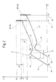
- Fig. 2 two curves 24, 24 'are shown as an example for the course of the pressing force over the path, the curve 24 is intended to be a comparison curve determined on the basis of sample workpieces.
- the press ram 19 In its position S B , the press ram 19 has reached the position in which the pressing process begins, so it must exert force in order to have the workpieces 21, 22 together.
- an increase in force is observed until after a camber 31, from adhesive friction when the pressing force decreases first again with further progression of the working stroke to finally come to rise again until upon reaching the joining position S F a force F F has reached.
- the pressing force F now rises steeply until the pressing process is interrupted and the ram 19 is retracted.
- the controller 11 continuously monitors the increase in the pressing force and now detects a strong change in the slope dF / ds or dF / dt at point F F , as a result of which the joining point is reached. Since the increase cannot be detected in any short time, there is a certain increase in the force ⁇ F to F m , which, however, does not cause any damage to the workpieces.
- the course of the curve 24 is also decisive for the result of the pressing process, so that the controller 11 monitors a whole series of parameters for compliance. These parameters include the joining position S F and the pressing force F. If, for example, the joining position S F is not reached, the pressing process was unsuccessful. However, since such a deviation does not necessarily have to indicate a failing pressing process, but rather can be attributed to the fact that the parts available are tolerated differently, the monitored parameters are now dynamically adapted on the basis of the curve 24.
- the curve 24 ' has a lower pressing force when the joining point S F ' is reached, namely the pressing force F F '. If the control 11 would now stop the pressing process only when the force F m is reached , an unnecessarily high force would be applied, which is undesirable for reasons already mentioned. However, the control 11 recognizes the steep increase in force and immediately stops the pressing operation, so that the force can only increase to the value F m '.
- the cant 31 an indication that the workpiece 21 is completely in the Workpiece 22 was pressed because namely for the other Pressing process first a lower force is required after this insertion was done.
- another parameter set W is used, which is indicated by a window 32 in FIG. 2.
- requirement for a successful pressing process is further that the Curve 24 passes through the window 32 and there is an elevation 31 shows.
- the curve can be any position in the window 32 have.
- sample workpieces are available, for which purpose not only the working stroke 28 of the electric press 10 but in particular the pressing force F of the press ram 19 is set by means of the electronic handwheel 15.
- the current course of the pressing force is shown in real time on the screen 12, so that the installer, who is recording a new curve 24, can fine-tune the pressing force using the electronic handwheel 15 and can check the result directly on the screen 12.
- Windows 32, 34 can then also be set on the screen 12.
- Now new sample workpieces are pressed, the current course of the pressing force being shown again on the screen 12 and at the same time the position of the windows 32, 34 can be checked.
- corresponding parameter sets are available, which include windows 32, 34 and the positions S B at the start of pressing 28 and S F at the end of the pressing process.
Landscapes
- Engineering & Computer Science (AREA)
- Mechanical Engineering (AREA)
- Control Of Presses (AREA)
- Manufacture Of Electron Tubes, Discharge Lamp Vessels, Lead-In Wires, And The Like (AREA)
- Apparatuses And Processes For Manufacturing Resistors (AREA)
Claims (8)
- Procédé d'exploitation d'une presse électrique (10) qui comporte un coulisseau de presse (19) actionné électriquement, au moins un capteur de course (25) pour détecter des positions (SB, SF) de la course du coulisseau de presse (19) dans sa course de travail (23), au moins un capteur de force (26) pour détecter la force de compression (F) appliquée par le coulisseau de presse (19) pendant la course de travail (23), sur les pièces à usiner (21, 22), ainsi qu'une commande (11) qui commande la course de travail (23), respectivement la course (s) et la force de compression (F), comportant les étapes suivantes :caractérisé en ce qu'en fonction de la variation (24) de la force de compression (F) sur la course (s) du coulisseau de presse (19), des paramètres (W) sont adaptés dynamiquement, qui indiquent un déroulement correct et/ou l'achèvement de l'opération de compression.a) déplacement du coulisseau de presse (19) dans sa position initiale (27),b) abaissement du coulisseau de presse (19) sur les pièces à usiner (21, 22) et mesure de la force de compression (F),c) détection du début de compression (28, SB) à l'aide d'une augmentation de la force de compression (F),d) poursuite de l'abaissement du coulisseau de presse (19) pour exécuter l'opération de compression et contrôle de la force de compression (F) appliquée, ainsi quee) arrêt du coulisseau de presse (19), lorsque celui-ci a atteint une position d'assemblage ou position terminale (29, SF),
- Procédé selon la revendication 1, caractérisé en ce que la position terminale (29, SF) est adaptée dynamiquement en fonction de la position du coulisseau de presse (19) en début de compression (28, SB).
- Procédé selon la revendication 1 ou 2, caractérisé en ce que la position terminale (29, SF) est adaptée dynamiquement en fonction d'une forte augmentation de la force de compression (F) dans la zone de la position terminale (29, SF).
- Procédé selon la revendication 3, caractérisé en ce que l'opération de compression est interrompue, de manière adaptée dynamiquement, en fonction de la forte augmentation de la force de compression (F ).
- Procédé selon l'une des revendications 1 à 4, caractérisé en ce que la variation (24) de la force de compression (F) sur la course (s) du coulisseau de presse (19) est surveillée quant au respect de jeux de paramètres déterminés (W 32, 34), les jeux de paramètres (W 32, 34) étant adaptés dynamiquement en fonction de la position du coulisseau de presse (19) en début de compression (28, SB).
- Procédé selon la revendication 5, caractérisé en ce que les jeux de paramètres (W 32, 34) sont déterminés par usinage et mesure de pièces échantillons.
- Procédé selon la revendication 6, caractérisé en ce que la variation (24) de la force de compression est indiquée en temps réel sur un écran (12), au moins pendant l'usinage de pièces échantillons.
- Procédé selon la revendication 6 ou 7, caractérisé en ce que la force de compression (F) appliquée est modifiée au moyen d'une roue manuelle électronique (15), au moins pendant l'usinage de pièces échantillons.
Applications Claiming Priority (3)
| Application Number | Priority Date | Filing Date | Title |
|---|---|---|---|
| DE19705462 | 1997-02-13 | ||
| DE19705462A DE19705462C2 (de) | 1997-02-13 | 1997-02-13 | Verfahren zum Betreiben einer Elektropresse |
| PCT/EP1998/000040 WO1998035823A1 (fr) | 1997-02-13 | 1998-01-07 | Procede pour faire fonctionner une presse electrique |
Publications (2)
| Publication Number | Publication Date |
|---|---|
| EP0960017A1 EP0960017A1 (fr) | 1999-12-01 |
| EP0960017B1 true EP0960017B1 (fr) | 2002-02-06 |
Family
ID=7820103
Family Applications (1)
| Application Number | Title | Priority Date | Filing Date |
|---|---|---|---|
| EP98907927A Expired - Lifetime EP0960017B1 (fr) | 1997-02-13 | 1998-01-07 | Procede pour faire fonctionner une presse electrique |
Country Status (5)
| Country | Link |
|---|---|
| US (1) | US6293155B1 (fr) |
| EP (1) | EP0960017B1 (fr) |
| AT (1) | ATE212903T1 (fr) |
| DE (2) | DE19705462C2 (fr) |
| WO (1) | WO1998035823A1 (fr) |
Families Citing this family (30)
| Publication number | Priority date | Publication date | Assignee | Title |
|---|---|---|---|---|
| GB9906389D0 (en) * | 1999-03-22 | 1999-05-12 | Hughes Glyn | Computer controlled mechanical press |
| TW553063U (en) * | 1999-08-03 | 2003-09-11 | Kosmek Kk | Device for obtaining calibration data of mechanical press, and load display device for mechanical press |
| DE10223153C1 (de) * | 2002-05-16 | 2003-07-31 | Schmidt Feinmech | Handbetätigte Presse |
| US7080595B2 (en) | 2002-05-16 | 2006-07-25 | Gebr. Schmidt Fabrik für Feinmechanik GmbH & Co. KG | Manually operated press |
| US6990896B2 (en) | 2002-10-15 | 2006-01-31 | Wabash Metal Products, Inc. | Electric high speed molding press |
| DE10333416B3 (de) * | 2003-07-17 | 2004-10-14 | Gebr. Schmidt Fabrik für Feinmechanik GmbH & Co. KG | Elektropresse |
| DE102005034424B4 (de) * | 2005-07-13 | 2007-09-27 | Gebr. Schmidt Fabrik für Feinmechanik GmbH & Co. KG | Handbetätigte Presse mit Überlastsicherung |
| DE102005040265A1 (de) * | 2005-08-24 | 2007-03-01 | Müller Weingarten AG | Verfahren und Vorrichtung zur Steuerung und Regelung von Kräften an servo-elektrischen Pressen |
| EP2099584B1 (fr) * | 2006-07-18 | 2017-10-25 | Kistler Holding AG | Unité d'assemblage |
| US8613814B2 (en) | 2008-03-21 | 2013-12-24 | California Institute Of Technology | Forming of metallic glass by rapid capacitor discharge forging |
| US8613816B2 (en) * | 2008-03-21 | 2013-12-24 | California Institute Of Technology | Forming of ferromagnetic metallic glass by rapid capacitor discharge |
| CN101977855B (zh) | 2008-03-21 | 2015-07-29 | 加利福尼亚技术学院 | 通过快速电容器放电形成金属玻璃 |
| US8499598B2 (en) | 2010-04-08 | 2013-08-06 | California Institute Of Technology | Electromagnetic forming of metallic glasses using a capacitive discharge and magnetic field |
| DE102010044688A1 (de) * | 2010-09-08 | 2012-03-08 | Dorst Technologies Gmbh & Co. Kg | Metall- oder Keramikpulver-Elektropresse und Steuerverfahren dafür |
| CN103328675B (zh) * | 2010-12-23 | 2016-01-06 | 加利福尼亚技术学院 | 通过迅速电容器放电的金属玻璃的片材形成 |
| JP5939545B2 (ja) | 2011-02-16 | 2016-06-22 | カリフォルニア インスティチュート オブ テクノロジー | 急速コンデンサ放電による金属ガラスの射出成形 |
| CA2829773A1 (fr) * | 2011-03-18 | 2012-09-27 | Abbvie Inc. | Systemes, dispositifs et procedes pour assembler des dispositifs a injection automatique et des sous-ensembles leur correspondant |
| US9393612B2 (en) | 2012-11-15 | 2016-07-19 | Glassimetal Technology, Inc. | Automated rapid discharge forming of metallic glasses |
| WO2014145747A1 (fr) | 2013-03-15 | 2014-09-18 | Glassimetal Technology, Inc. | Procédés de mise en forme d'articles présentant un côté élevé à partir d'alliages de verre métallique faisant appel à une décharge capacitive rapide et à une charge d'alimentation en verre métallique destinées à être utilisés dans ces procédés |
| JP6257971B2 (ja) | 2013-09-09 | 2018-01-10 | 蛇の目ミシン工業株式会社 | 電動プレス、判断方法およびプログラム |
| JP6257970B2 (ja) | 2013-09-09 | 2018-01-10 | 蛇の目ミシン工業株式会社 | 電動プレス、屈曲点検出方法およびプログラム |
| JP2015051453A (ja) * | 2013-09-09 | 2015-03-19 | 蛇の目ミシン工業株式会社 | 電動プレス、屈曲点検出方法およびプログラム |
| US10273568B2 (en) | 2013-09-30 | 2019-04-30 | Glassimetal Technology, Inc. | Cellulosic and synthetic polymeric feedstock barrel for use in rapid discharge forming of metallic glasses |
| CN104630661B (zh) | 2013-10-03 | 2017-04-26 | 格拉斯金属技术股份有限公司 | 用于金属玻璃的快速放电形成的涂覆有绝缘膜的进料桶 |
| US10029304B2 (en) | 2014-06-18 | 2018-07-24 | Glassimetal Technology, Inc. | Rapid discharge heating and forming of metallic glasses using separate heating and forming feedstock chambers |
| US10022779B2 (en) | 2014-07-08 | 2018-07-17 | Glassimetal Technology, Inc. | Mechanically tuned rapid discharge forming of metallic glasses |
| DE102014110507A1 (de) * | 2014-07-25 | 2016-01-28 | Ief-Werner Gmbh | Pressverfahren mit Kompensation von Positionierfehlern bei einem Pressvorgang und Presse zur Durchführung eines solchen Verfahrens |
| US10682694B2 (en) | 2016-01-14 | 2020-06-16 | Glassimetal Technology, Inc. | Feedback-assisted rapid discharge heating and forming of metallic glasses |
| US10632529B2 (en) | 2016-09-06 | 2020-04-28 | Glassimetal Technology, Inc. | Durable electrodes for rapid discharge heating and forming of metallic glasses |
| EP4570487A1 (fr) * | 2023-12-11 | 2025-06-18 | Kistler Holding AG | Module d'assemblage électromécanique |
Family Cites Families (11)
| Publication number | Priority date | Publication date | Assignee | Title |
|---|---|---|---|---|
| US4750131A (en) * | 1985-09-11 | 1988-06-07 | Rca Licensing Corporation | Method of detecting faulty parts in a progressive die press |
| JPS63180400A (ja) * | 1987-01-23 | 1988-07-25 | Nkk Corp | プレス機の自動荷重制御装置 |
| DE3715077A1 (de) * | 1987-05-06 | 1988-12-01 | Netzsch Maschinenfabrik | Verfahren zum steuern einer presse |
| US5119311A (en) * | 1988-07-14 | 1992-06-02 | Coors Brewing Company | Monitor and control assembly for use with a can end press |
| US4939665A (en) * | 1988-07-14 | 1990-07-03 | Adolph Coors Company | Monitor and control assembly for use with a can end press |
| DE9014783U1 (de) * | 1990-10-25 | 1992-02-20 | Robert Bosch Gmbh, 7000 Stuttgart | Motorgetriebene Presse mit Kraft- und Wegsensoren |
| JP3472316B2 (ja) * | 1993-01-26 | 2003-12-02 | 蛇の目ミシン工業株式会社 | プレス機械 |
| US5483874A (en) * | 1994-03-18 | 1996-01-16 | Janome Sewing Machine Co., Ltd. | Electropressing apparatus with computer programmable control |
| US5564298A (en) * | 1994-11-01 | 1996-10-15 | Aluminum Company Of America | Die tool and press monitor and product quality analysis apparatus and method |
| US5669257A (en) | 1994-12-28 | 1997-09-23 | Yazaki Corporation | Method of crimping terminal and apparatus for the same |
| JPH08224699A (ja) | 1995-02-23 | 1996-09-03 | Mitsubishi Electric Corp | プレス制御方法およびプレス装置 |
-
1997
- 1997-02-13 DE DE19705462A patent/DE19705462C2/de not_active Expired - Fee Related
-
1998
- 1998-01-07 DE DE59803009T patent/DE59803009D1/de not_active Expired - Lifetime
- 1998-01-07 WO PCT/EP1998/000040 patent/WO1998035823A1/fr not_active Ceased
- 1998-01-07 AT AT98907927T patent/ATE212903T1/de active
- 1998-01-07 EP EP98907927A patent/EP0960017B1/fr not_active Expired - Lifetime
-
1999
- 1999-08-12 US US09/373,286 patent/US6293155B1/en not_active Expired - Lifetime
Also Published As
| Publication number | Publication date |
|---|---|
| WO1998035823A1 (fr) | 1998-08-20 |
| DE59803009D1 (de) | 2002-03-21 |
| EP0960017A1 (fr) | 1999-12-01 |
| DE19705462A1 (de) | 1998-08-20 |
| US6293155B1 (en) | 2001-09-25 |
| ATE212903T1 (de) | 2002-02-15 |
| DE19705462C2 (de) | 2002-01-10 |
Similar Documents
| Publication | Publication Date | Title |
|---|---|---|
| EP0960017B1 (fr) | Procede pour faire fonctionner une presse electrique | |
| DE102005014416B4 (de) | Luftservozylindervorrichtung und Steuerverfahren hierfür | |
| AT510949B1 (de) | Steuer- und regelvorrichtung für eine biegepresse | |
| DE4242442C2 (de) | Verfahren zum Einstellen der Klemmkraft des Niederhalters von Ziehpressen | |
| DE102004012294B4 (de) | Hochgeschwindigkeitsantriebsverfahren und -system für Druckzylinder | |
| DE10027156A1 (de) | Schutzeinrichtung für Maschinen, wie Abkantpressen, Schneidmaschinen, Stanzmaschinen oder dergleichen | |
| EP0585589B1 (fr) | Procédé pour l'optimisation de processus d'emboutissage automatique et itératif aux presses | |
| EP3408056A1 (fr) | Procédé permettant de faire fonctionner un outil de travail et outil de travail | |
| EP2559116B1 (fr) | Presse de sertissage | |
| DE19721272B4 (de) | Elektrische Preßvorrichtung | |
| DE102013105468A1 (de) | Verfahren zur Steuerung einer Presse mit variabler Getriebeübersetzung | |
| EP3313654B1 (fr) | Procédé de détermination d'une caractéristique d'utilisation d'un outil de moulage par compression d'une presse d'assemblage | |
| DE10144286C1 (de) | Verfahren zur Beurteilung der Qualität einer Schweißverbindung | |
| EP0288719B1 (fr) | Dispositif de commande pour installation de puissance pneumatique-hydraulique | |
| DE4109795A1 (de) | Verfahren und einrichtung zum stanzen, biegen und/oder pressen | |
| EP3487647A1 (fr) | Procédé et dispositif pour cisailler un matériau en tige | |
| EP2431650A1 (fr) | Système de protection pour unité de commande sur des machines, notamment des presses de pliage | |
| EP2586544B1 (fr) | Machine-outil avec un dispositif de butée et procédé de fonctionnement de la machine-outil | |
| EP0284903B1 (fr) | Presse à piston | |
| EP1582285A2 (fr) | Méthode de soudage par résistance et d'évalution de la qualité d'une soudure | |
| EP1136146B1 (fr) | Méthode de pliage des tôles et machine pour la mise en oeuvre de cette méthode | |
| EP2105237A2 (fr) | Procédé destiné à la commande d'une force de pression à électrodes pour une pince à souder tout comme pince à souder correspondante | |
| DE102004034037B4 (de) | Verfahren zum programmgesteuerten automatischen Positionieren der beiden Enden eines Werkstücks bei wählbaren Längentoleranzen | |
| EP0607498A1 (fr) | Méthode de commande d'une presse à couper et une presse à couper | |
| DE10214618A1 (de) | Verfahren zum Bearbeiten von Werkstücken mittels eines Bearbeitungsverfahren, insbesondere des elektrochemischen Bearbeitungsverfahrens |
Legal Events
| Date | Code | Title | Description |
|---|---|---|---|
| PUAI | Public reference made under article 153(3) epc to a published international application that has entered the european phase |
Free format text: ORIGINAL CODE: 0009012 |
|
| 17P | Request for examination filed |
Effective date: 19981214 |
|
| AK | Designated contracting states |
Kind code of ref document: A1 Designated state(s): AT BE CH DE FR GB LI |
|
| GRAG | Despatch of communication of intention to grant |
Free format text: ORIGINAL CODE: EPIDOS AGRA |
|
| 17Q | First examination report despatched |
Effective date: 20010330 |
|
| RAP1 | Party data changed (applicant data changed or rights of an application transferred) |
Owner name: GEBR. SCHMIDT FABRIK FUER FEINMECHANIK GMBH & CO. |
|
| GRAG | Despatch of communication of intention to grant |
Free format text: ORIGINAL CODE: EPIDOS AGRA |
|
| GRAH | Despatch of communication of intention to grant a patent |
Free format text: ORIGINAL CODE: EPIDOS IGRA |
|
| GRAH | Despatch of communication of intention to grant a patent |
Free format text: ORIGINAL CODE: EPIDOS IGRA |
|
| GRAA | (expected) grant |
Free format text: ORIGINAL CODE: 0009210 |
|
| REG | Reference to a national code |
Ref country code: GB Ref legal event code: IF02 |
|
| AK | Designated contracting states |
Kind code of ref document: B1 Designated state(s): AT BE CH DE FR GB LI |
|
| REF | Corresponds to: |
Ref document number: 212903 Country of ref document: AT Date of ref document: 20020215 Kind code of ref document: T |
|
| REG | Reference to a national code |
Ref country code: CH Ref legal event code: EP |
|
| REG | Reference to a national code |
Ref country code: CH Ref legal event code: NV Representative=s name: TROESCH SCHEIDEGGER WERNER AG |
|
| REF | Corresponds to: |
Ref document number: 59803009 Country of ref document: DE Date of ref document: 20020321 |
|
| ET | Fr: translation filed | ||
| GBT | Gb: translation of ep patent filed (gb section 77(6)(a)/1977) |
Effective date: 20020513 |
|
| PLBE | No opposition filed within time limit |
Free format text: ORIGINAL CODE: 0009261 |
|
| STAA | Information on the status of an ep patent application or granted ep patent |
Free format text: STATUS: NO OPPOSITION FILED WITHIN TIME LIMIT |
|
| 26N | No opposition filed |
Effective date: 20021107 |
|
| REG | Reference to a national code |
Ref country code: FR Ref legal event code: PLFP Year of fee payment: 19 |
|
| PGFP | Annual fee paid to national office [announced via postgrant information from national office to epo] |
Ref country code: CH Payment date: 20160120 Year of fee payment: 19 |
|
| PGFP | Annual fee paid to national office [announced via postgrant information from national office to epo] |
Ref country code: GB Payment date: 20160120 Year of fee payment: 19 Ref country code: AT Payment date: 20160121 Year of fee payment: 19 Ref country code: FR Payment date: 20160121 Year of fee payment: 19 Ref country code: BE Payment date: 20160120 Year of fee payment: 19 |
|
| PGFP | Annual fee paid to national office [announced via postgrant information from national office to epo] |
Ref country code: DE Payment date: 20170223 Year of fee payment: 20 |
|
| PG25 | Lapsed in a contracting state [announced via postgrant information from national office to epo] |
Ref country code: BE Free format text: LAPSE BECAUSE OF NON-PAYMENT OF DUE FEES Effective date: 20170131 |
|
| REG | Reference to a national code |
Ref country code: CH Ref legal event code: PL |
|
| REG | Reference to a national code |
Ref country code: AT Ref legal event code: MM01 Ref document number: 212903 Country of ref document: AT Kind code of ref document: T Effective date: 20170107 |
|
| GBPC | Gb: european patent ceased through non-payment of renewal fee |
Effective date: 20170107 |
|
| REG | Reference to a national code |
Ref country code: FR Ref legal event code: ST Effective date: 20170929 |
|
| PG25 | Lapsed in a contracting state [announced via postgrant information from national office to epo] |
Ref country code: LI Free format text: LAPSE BECAUSE OF NON-PAYMENT OF DUE FEES Effective date: 20170131 Ref country code: CH Free format text: LAPSE BECAUSE OF NON-PAYMENT OF DUE FEES Effective date: 20170131 Ref country code: AT Free format text: LAPSE BECAUSE OF NON-PAYMENT OF DUE FEES Effective date: 20170107 Ref country code: FR Free format text: LAPSE BECAUSE OF NON-PAYMENT OF DUE FEES Effective date: 20170131 |
|
| PG25 | Lapsed in a contracting state [announced via postgrant information from national office to epo] |
Ref country code: GB Free format text: LAPSE BECAUSE OF NON-PAYMENT OF DUE FEES Effective date: 20170107 |
|
| REG | Reference to a national code |
Ref country code: DE Ref legal event code: R071 Ref document number: 59803009 Country of ref document: DE |
|
| REG | Reference to a national code |
Ref country code: BE Ref legal event code: MM Effective date: 20170131 |