EP0960252B1 - Tragebandwickelvorrichtung für fensterabdeckung - Google Patents
Tragebandwickelvorrichtung für fensterabdeckung Download PDFInfo
- Publication number
- EP0960252B1 EP0960252B1 EP97930087A EP97930087A EP0960252B1 EP 0960252 B1 EP0960252 B1 EP 0960252B1 EP 97930087 A EP97930087 A EP 97930087A EP 97930087 A EP97930087 A EP 97930087A EP 0960252 B1 EP0960252 B1 EP 0960252B1
- Authority
- EP
- European Patent Office
- Prior art keywords
- spindle
- suspension cord
- cord
- finger
- tilt rod
- Prior art date
- Legal status (The legal status is an assumption and is not a legal conclusion. Google has not performed a legal analysis and makes no representation as to the accuracy of the status listed.)
- Expired - Lifetime
Links
- 239000000725 suspension Substances 0.000 title claims description 59
- 238000004804 winding Methods 0.000 title claims description 32
- 230000001413 cellular effect Effects 0.000 description 2
- 239000011324 bead Substances 0.000 description 1
- 230000002939 deleterious effect Effects 0.000 description 1
- 238000001125 extrusion Methods 0.000 description 1
- 230000005484 gravity Effects 0.000 description 1
- 238000002347 injection Methods 0.000 description 1
- 239000007924 injection Substances 0.000 description 1
- 238000001746 injection moulding Methods 0.000 description 1
- 238000004519 manufacturing process Methods 0.000 description 1
- 238000000465 moulding Methods 0.000 description 1
Images


Classifications
-
- E—FIXED CONSTRUCTIONS
- E06—DOORS, WINDOWS, SHUTTERS, OR ROLLER BLINDS IN GENERAL; LADDERS
- E06B—FIXED OR MOVABLE CLOSURES FOR OPENINGS IN BUILDINGS, VEHICLES, FENCES OR LIKE ENCLOSURES IN GENERAL, e.g. DOORS, WINDOWS, BLINDS, GATES
- E06B9/00—Screening or protective devices for wall or similar openings, with or without operating or securing mechanisms; Closures of similar construction
- E06B9/24—Screens or other constructions affording protection against light, especially against sunshine; Similar screens for privacy or appearance; Slat blinds
- E06B9/26—Lamellar or like blinds, e.g. venetian blinds
- E06B9/28—Lamellar or like blinds, e.g. venetian blinds with horizontal lamellae, e.g. non-liftable
- E06B9/30—Lamellar or like blinds, e.g. venetian blinds with horizontal lamellae, e.g. non-liftable liftable
- E06B9/303—Lamellar or like blinds, e.g. venetian blinds with horizontal lamellae, e.g. non-liftable liftable with ladder-tape
- E06B9/307—Details of tilting bars and their operation
-
- E—FIXED CONSTRUCTIONS
- E06—DOORS, WINDOWS, SHUTTERS, OR ROLLER BLINDS IN GENERAL; LADDERS
- E06B—FIXED OR MOVABLE CLOSURES FOR OPENINGS IN BUILDINGS, VEHICLES, FENCES OR LIKE ENCLOSURES IN GENERAL, e.g. DOORS, WINDOWS, BLINDS, GATES
- E06B9/00—Screening or protective devices for wall or similar openings, with or without operating or securing mechanisms; Closures of similar construction
- E06B9/24—Screens or other constructions affording protection against light, especially against sunshine; Similar screens for privacy or appearance; Slat blinds
- E06B9/26—Lamellar or like blinds, e.g. venetian blinds
- E06B9/28—Lamellar or like blinds, e.g. venetian blinds with horizontal lamellae, e.g. non-liftable
- E06B9/30—Lamellar or like blinds, e.g. venetian blinds with horizontal lamellae, e.g. non-liftable liftable
- E06B9/303—Lamellar or like blinds, e.g. venetian blinds with horizontal lamellae, e.g. non-liftable liftable with ladder-tape
- E06B9/306—Lamellar or like blinds, e.g. venetian blinds with horizontal lamellae, e.g. non-liftable liftable with ladder-tape with tilting bar along which the raising cords are guided
-
- E—FIXED CONSTRUCTIONS
- E06—DOORS, WINDOWS, SHUTTERS, OR ROLLER BLINDS IN GENERAL; LADDERS
- E06B—FIXED OR MOVABLE CLOSURES FOR OPENINGS IN BUILDINGS, VEHICLES, FENCES OR LIKE ENCLOSURES IN GENERAL, e.g. DOORS, WINDOWS, BLINDS, GATES
- E06B9/00—Screening or protective devices for wall or similar openings, with or without operating or securing mechanisms; Closures of similar construction
- E06B9/24—Screens or other constructions affording protection against light, especially against sunshine; Similar screens for privacy or appearance; Slat blinds
- E06B9/26—Lamellar or like blinds, e.g. venetian blinds
- E06B9/28—Lamellar or like blinds, e.g. venetian blinds with horizontal lamellae, e.g. non-liftable
- E06B9/30—Lamellar or like blinds, e.g. venetian blinds with horizontal lamellae, e.g. non-liftable liftable
- E06B9/303—Lamellar or like blinds, e.g. venetian blinds with horizontal lamellae, e.g. non-liftable liftable with ladder-tape
- E06B9/308—Lamellar or like blinds, e.g. venetian blinds with horizontal lamellae, e.g. non-liftable liftable with ladder-tape with coaxial tilting bar and raising shaft
Definitions
- the present invention relates generally to window coverings, and more particularly to devices for raising the slats of horizontal window blinds.
- Window coverings such as horizontal blinds, horizontal pleated shades, and cellular shades include horizontally-oriented slats.
- the slats of a window covering are suspended from a head rail of the window covering by means of a plurality of cords.
- Certain of the cords referred to herein as tilt cords, can be operated to, e.g., tilt the slats of a horizontal blind.
- Certain other of the cords referred to herein as suspension cords, can be operated to raise the slats of a blind or pleated shade.
- the suspension cord of a window covering such as a horizontal blind extends into the head rail through an opening in the head rail.
- the suspension cord can be pulled axially to raise the slats, and it can also be released to permit the slats to lower under the influence of gravity.
- window coverings which include a suspension cord that is pulled by a motor.
- the suspension cord typically is connected to a so-called tilt rod that is rotatably mounted in the head rail, and the tilt rod can be rotated by a motor to wind the suspension cord onto the tilt rod and thereby raise the slats, without requiring a person to manually pull the suspension cord.
- U.S. Pat. No. 5,495,153 assigned to the same assignee to which the present invention is assigned and incorporated herein by reference, discloses one such system.
- devices for smoothly guiding a suspension cord onto a tilt rod, such that successive coils of the cord do not overlap. This is to ensure smooth operation of the system during winding (i.e., raising the slats) and unwinding (i.e., lowering the slats).
- a suspension cord is affixed to a winding drum having a shoulder formed on one end.
- the drum is telescoped onto the head rail, and the drum has a radially enlarged segment next to the shoulder and a radially smaller segment extending from the radially enlarged segment.
- the cord is guided onto the radially enlarged segment tangentially to the shoulder, and when the winding drum is rotated, the shoulder pushes successive coils of the cord off the radially enlarged segment and onto the radially smaller segment.
- the Somfy device has several drawbacks. Specifically, because the Somfy device requires a radially enlarged segment for cooperating with the shoulder to move the suspension cord coils along the drum, the suspension cord must bend around the radially enlarged segment as it enters the head rail through the head rail opening. This causes undesirably high frictional losses as the cord rubs against the edge of the opening. Such relatively high friction losses are particularly deleterious in systems that use battery-powered motors to turn the head rail, because battery-powered systems, to be commercially feasible, must be characterized by relatively long battery life.
- a suspension cord guide for a window covering which does not induce unwanted large frictional losses during winding of the suspension cord within a head rail, and which permits easy adjustment of the suspension cord end within the head rail. Accordingly, it is an object of the present invention to provide a device for guiding a suspension cord into a head rail of a window covering which does not induce large frictional losses. Another object of the present invention is to provide a device for guiding a suspension cord into a head rail of a window covering which can be used with large and small window coverings. Still another object of the present invention is to provide a device for guiding a suspension cord into a head rail of a window covering which is easy to use and cost-effective.
- a device for winding at least one suspension cord of a window covering having slats, a horizontally-oriented head rail, and a tilt rod disposed in the head rail.
- the head rail is formed with an opening through which the suspension cord extends.
- the device includes a hollow spindle that surroundingly engages the tilt rod and that is rotatable therewith.
- the spindle includes a winding surface which defines a first end, and the suspension cord establishes a plurality of coils on the winding surface at least when the slats are not in a fully lowered configuration.
- the device includes a guide finger which is disposed in the head rail adjacent the opening and which extends toward the spindle, with the suspension cord extending through the opening between the finger and the first end.
- the finger is oriented such that the finger contacts at least one coil, thereby pushing coils of the suspension cord formed on the winding surface away from the finger such that successive coils are established on the winding surface of the spindle without overlapping.
- the window covering includes a tilt cord that is engaged with the slats for tilting the slats
- the device includes a pulley formed with a tilt cord groove for receiving the tilt cord.
- the pulley establishes a radial abutment on the first end of the spindle.
- the tilt cord groove is characterized by a rectangular cross-section.
- the device includes a lower mount and an upper mount, and the mounts are engaged with each other and with the head rail.
- the finger is formed on the lower mount.
- the spindle is disposed between the mounts, with the upper mount being formed with a curved channel closely spaced from the spindle.
- the tilt rod defines a transverse cross-section
- the device includes a hollow adapter having a central passageway configured for closely engaging the tilt rod.
- the adapter defines an outer surface that is receivable within the spindle in an interference fit therewith to thereby couple the tilt rod to the spindle.
- a clip is formed with a rod groove configured for closely engaging the tilt rod and a cord groove juxtaposed with the rod groove and oriented parallel thereto for closely receiving the suspension cord. The clip consequently can hold the suspension cord stationary relative to the tilt rod.
- a window covering is disclosed which incorporates the device discussed above.
- a device for winding the suspension cord of a window covering when a tilt rod of the window covering is rotated.
- the device includes a spindle engaged with the tilt rod, and an L-shaped guide member juxtaposed with the spindle.
- the L-shaped guide member guides the suspension cord onto the spindle and contacts a coil of the suspension cord to push the coils along the spindle such that successive coils are formed on the spindle without overlapping each other.
- a suspension cord winding device is shown in operable engagement with a head rail 12 of a window blind 14.
- the window blind 14 is a horizontal-type venetian blind having a plurality of horizontally-oriented slats 16.
- the slats 16 are suspended from the head rail 12 by means of suspension cords 18 and tilt cords 20 (only one suspension cord 18 and one tilt cord 20 shown in Figure 1).
- Figure 1 shows the device 10 in operable engagement with a horizontal-type window blind 14, the device 10 can be used with other types of window coverings, e.g., cellular shades, pleated shades, and Roman shades.
- the cords 18, 20 extend into the head rail 12 through opposed elongated rectangular or ovular openings 22 that are formed in the head rail 12 (only one opening 22 shown for clarity of disclosure). It can be appreciated in reference to Figure 1 that the cords 18, 20 are coupled, via the device 10, to a tilt rod 24 that is disposed in the head rail 12 more or less coaxially with the head rail 12.
- the tilt rod 24 shown in Figure 1 is characterized by a hexagonal transverse cross-section as shown.
- the tilt rod 24 can be rotated to move the suspension cord 18 and thereby raise and lower the slats, or to move the tilt cord 20 and thereby tilt the slats about their respective axes.
- the tilt rod 24 is engaged with a motorized mechanism as disclosed in U.S. Pat. No. 5,495,153, incorporated herein by reference, to facilitate automatic and remote operation of the tilt rod 24.
- each opening 22 of the head rail 12 is associated with a respective winding device of the present invention.
- the device 10 shown in the Figures will be described herein.
- the device 10 includes a hollow tubular spindle 26.
- the spindle 26 surroundingly engages the tilt rod 24 and rotates with the tilt rod 24 as discussed further below.
- Figure 2 best shows that the spindle 26 defines a generally cylindrical winding surface 28 that in turn defines a left end (looking down on Figure 1), and a pulley 32 is formed integrally with the winding surface 28 on the left end.
- the pulley 32 establishes a radial abutment surface 34.
- winding surface 28 is generally cylindrical, and indeed may be exactly cylindrical, it is to be understood that the winding surface 28 can be slightly tapered inwardly away from the pulley 32, to facilitate removing the spindle 26 from an injection mold.
- the spindle 26 can be made by extrusion principles well-known in the art, in which case the winding surface can be exactly cylindrical.
- the spindle 26 need be slightly tapered only for injection molding manufacturing purposes, not for functional purposes, for reasons to be shortly disclosed.
- Figures 2 and 3 show that the pulley 32 is circumscribed by a tilt cord groove 36 that is characterized by a rectangular cross-section. As shown, the tilt cord 20 is received in the tilt cord groove 36 of the pulley 32. I have discovered that the rectangular cross-section of the tilt cord groove 36 affords improved tilting capability vis-a-vis pulley grooves having other shapes, e.g., V-shaped grooves. As the skilled artisan will appreciate, when the spindle 26 is rotated, the pulley 32 rotates to move the tilt cord 20 translationally in the vertical dimension.
- a guide is snappingly engaged with the head rail 12 in a surrounding relationship with the spindle 26.
- the guide 38 includes an upper mount 40 and a lower mount 42.
- the upper mount 40 is formed with an L-shaped flange 44 that is complementarily configured with a rear flange 12a of the head rail 12 for flushly abutting the rear flange 12a.
- the lower mount 42 is formed with an L-shaped flange 46 that is complementarily configured with a front flange 12b of the head rail 12 for flushly abutting the front flange 12b.
- the mounts 40, 42 are dimensioned such that when the mounts 40, 42 are connected together as described below to establish the guide 38, the L-shaped flanges 44, 46 cooperate with the flanges 12a, 12b of the head rail 12 to facilitate an interference fit between the guide 38 and the head rail 12.
- the spindle 26 is positioned between the mounts 40, 42.
- the upper mount 40 is formed with a curved spindle channel 48 that is configured complentarily to the spindle 26, with the wall of the spindle channel 48 being closely spaced from the spindle 26.
- the wall of the spindle channel 48 is distanced from the spindle 26 by a distance about equal to the diameter of the suspension cord 18.
- the upper mount 40 is formed with an elongated, generally parallelepiped-shaped snap element 50, while the lower mount 42 is formed with a snap aperture 52 defining a snap edge 54.
- the snap element 50 is snappingly received in the snap aperture 52 against the edge 54.
- the lower mount 42 includes a floor 56 that is bounded in the rear by an upwardly oriented rear wall 58. Additionally, the floor 56 is bounded on its sides by right and left side walls 60, 62. As shown, the right side wall 60 defines an insert bearing notch 64, and a guide wall portion 66 of the right side wall 60 extends between the bearing notch 64 and a front wall 68. As shown in Figure 2, the front flange 46 is formed on the front wall 68 along the upper edge thereof.
- an opening 70 is formed in the floor 56.
- the opening 70 is shaped and sized substantially like the opening 22 of the head rail 12, and is juxtaposed therewith.
- a finger 72 is formed on the floor 56 next to the opening 70, and the finger 72 extends upwardly from the floor 56 toward the spindle 26, adjacent the pulley 32. Also, the finger 72 is elongated and is parallel to the long axis of the opening 70, as shown. A rear end 73 of the finger 72 is bevelled.
- the height of the finger 72 relative the floor 56 is established such that the finger 72 is closely spaced from the spindle 26, but does not touch the spindle 26. More particularly, the finger 72 is spaced a distance "D" from the spindle 26, with the distance "D" being less than the radius of the suspension cord 18, for reasons to be shortly disclosed. In the preferred embodiment, the distance "D" is equal to about five thousandths of an inch (0.005"). It can be appreciated in reference to Figure 3 that the finger 72, together with the floor 56 of the lower mount 42, establishes an L-shaped guide member.
- a semi-circularly shaped cord notch 74 is formed in the floor 56 of the lower mount 42, with the notch 74 communicating with the opening 70 and extending laterally away therefrom. Further, a fingernail-shaped bearing groove 76 extends laterally away from the cord notch 74 opposite the opening 70 as shown. As can be appreciated in reference to Figure 2, the bottom surface 78 of the bearing groove 76 gradually rises from the cord notch 74 to meet the planar surface of the floor 56 of the lower mount 42.
- the suspension cord 18 extends through the opening 22 of the head rail 12 and through the cord notch 74 of the lower mount 42. It may be further appreciated that the suspension cord 18 extends onto the spindle 26 between the pulley 32 and the finger 72, and that the suspension cord 18 establishes a plurality of coils 18a (Figure 3) on the winding surface 28 at least when the slats 16 are not in a fully lowered configuration. As shown in Figure 3, the coils 18a are disposed on the winding surface 28 on the side of the finger 72 opposite the pulley 32, with the finger 72 contacting a first coil 80.
- the finger 72 is oriented such that the finger 72 contacts the first coil 80.
- the cooperation between the finger 72 and the suspension cord 18 pushes the coils 18a away from the finger 72, such that successive coils are established on the winding surface of the spindle without overlapping.
- the combination of structure described above including the elongated finger 72 with bevelled rear end 73, semi-circular cord notch 74, and bearing groove 76, facilitates smoothly winding the suspension cord 18 through the notch 74 and onto the winding surface 28 of the spindle 26.
- the present combination of structure facilitates continuous smooth guiding and winding of the suspension cord 18 as the coils 18a are established on the winding surface 28 of the spindle 26, thus further minimizing large frictional losses.
- the spindle 26 rotates with the tilt rod 24.
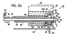
- a hollow adapter 82 is advanced into the spindle 26 in an interference fit therewith, as shown in Figure 3A, or the hollow adaptor 82 is formed integrally with the spindle 26 during molding, as shown in Figure 3.
- the adapter 82 is formed with a cylindrical outer surface.
- the adapter 82 is formed with a central passageway 84 that is configured for closely engaging the tilt rod 24, e.g., the central passageway 84 defines a hexagonal cross-section when it is desired to couple the spindle 26 with a tilt rod 24 that has a hexagonal cross-section. Consequently, the adapter 82 is advanced over the tilt rod 24 to thereby couple tilt rod 24 to the spindle 26.
- the suspension cord 18 can be adjustably affixed to the tilt rod 24 by a clip 86.
- the clip 86 is formed with a rod groove 88 that is configured for closely engaging the tilt rod 24, e.g., the rod groove 88 has a hexagonal transverse cross-section for engaging the particular tilt rod 24 shown.
- the clip 86 is formed with a cylindrical cord groove 90 which is oriented parallel to the rod groove 88. It can be appreciated in reference to Figure 2 that the cord groove 90 closely receives the suspension cord 18 to thereby hold the suspension cord 18 stationary relative to the tilt rod 24.
- a bead 92 can be attached to the suspension cord 18 to prevent the suspension cord 18 from being pulled out of the cord groove 90.
- the clip 86 can be slid on the tilt rod 24 as appropriate to adjustably affix the cord 18 to the tilt rod 24 at a desired location on the tilt rod 24.
- the present invention can easily be adapted for use on a wide variety of window coverings.
- devices such as the one disclosed in the above-mentioned Somfy patent, in which the end of the suspension cord is affixed to the winding drum instead of the tilt rod, cannot easily be adjusted to affix of the end suspension cord at a location that is optimal for the particular window covering.
Landscapes
- Engineering & Computer Science (AREA)
- Structural Engineering (AREA)
- Architecture (AREA)
- Civil Engineering (AREA)
- Blinds (AREA)
Claims (9)
- Vorrichtung (10) zum Aufwickeln einer Tragkordel (18) einer Fensterabdeckung, wobei die Vorrichtung (10) eine Kippstange (24) zum Aufwickeln der Tragkordel beim Drehen der Kippstange sowie eine Spindel (26) aufweist, die in Eingriff mit der Kippstange bringbar und an einem unteren Gehäuseteil (42) angeordnet ist, der mit einer Öffnung (70) versehen ist, durch welche die Tragkordel (18) hindurchläuft, dadurch gekennzeichnet, dass die Vorrichtung einen Finger (72) aufweist, der nahe an der Öffnung (70) angebracht und zur Spindel (26) benachbart ist und zur Führung der Tragkordel (18) auf der Spindel und zur Berührung einer Wicklung der Tragkordel zwecks Verschiebung der Wicklungen (18a) entlang der Spindel, wenn sich die Spindel in Eingriff mit der Kippstange befindet, vorgesehen ist, derart, dass aufeinander folgende Wicklungen auf der Spindel ausgebildet werden, ohne dass sie übereinander laufen.
- Vorrichtung (10) nach Anspruch 1, dadurch gekennzeichnet, dass das untere Gehäuseteil (42) mit einem oberen Gehäuseteil (44) zusammenhängt, und dass die Spindel (26) zwischen dem unteren Gehäuseteil (42) und dem oberen Gehäuseteil (44) angeordnet ist.
- Vorrichtung (10) nach Anspruch 2, dadurch gekennzeichnet, dass das obere Gehäuseteil (44) mit einer gekrümmten Ausnehmung (48) versehen ist.
- Vorrichtung (10) nach einem der vorhergehenden Ansprüche, dadurch gekennzeichnet, dass sich der Finger (72) in Richtung der Spindel (26) erstreckt.
- Vorrichtung (10) nach einem der vorhergehenden Ansprüche, dadurch gekennzeichnet, dass der Finger (72) ein abgeschrägtes rückwärtiges Ende (73) aufweist.
- Vorrichtung (10) nach einem der vorhergehenden Ansprüche, dadurch gekennzeichnet, dass der Finger (72) in einem Abstand von der Spindel (26) angeordnet ist, der kleiner ist als der Radius der Tragkordel (18).
- Vorrichtung (10) nach einem der vorhergehenden Ansprüche, dadurch gekennzeichnet, dass der Finger (72) in einem Abstand von der Spindel (26) angeordnet ist, der etwa 0,1 mm beträgt.
- Vorrichtung (10) nach einem der Ansprüche 2 bis 7, dadurch gekennzeichnet, dass sie eine Kopfschiene (12) aufweist, an welcher die Gehäuseteile (42, 44) angebracht sind.
- Vorrichtung (10) nach einem der vorhergehenden Ansprüche, dadurch gekennzeichnet, dass der Finger (72) an einem Boden (56) des unteren Gehäuseteils (42) angeformt ist.
Applications Claiming Priority (3)
| Application Number | Priority Date | Filing Date | Title |
|---|---|---|---|
| US666249 | 1996-06-20 | ||
| US08/666,249 US5725040A (en) | 1996-06-20 | 1996-06-20 | Suspension cord winding device for window covering |
| PCT/US1997/010536 WO1997048871A1 (en) | 1996-06-20 | 1997-06-16 | Suspension cord winding device for window covering |
Publications (3)
| Publication Number | Publication Date |
|---|---|
| EP0960252A1 EP0960252A1 (de) | 1999-12-01 |
| EP0960252A4 EP0960252A4 (de) | 2002-11-06 |
| EP0960252B1 true EP0960252B1 (de) | 2006-01-11 |
Family
ID=24673411
Family Applications (1)
| Application Number | Title | Priority Date | Filing Date |
|---|---|---|---|
| EP97930087A Expired - Lifetime EP0960252B1 (de) | 1996-06-20 | 1997-06-16 | Tragebandwickelvorrichtung für fensterabdeckung |
Country Status (5)
| Country | Link |
|---|---|
| US (1) | US5725040A (de) |
| EP (1) | EP0960252B1 (de) |
| AU (1) | AU3400097A (de) |
| DE (1) | DE69735102T2 (de) |
| WO (1) | WO1997048871A1 (de) |
Families Citing this family (25)
| Publication number | Priority date | Publication date | Assignee | Title |
|---|---|---|---|---|
| TW326240U (en) * | 1997-09-02 | 1998-02-01 | Fu-Mei Fan | Improved structure of a height adjustable curtain track |
| US6648050B1 (en) | 1997-11-04 | 2003-11-18 | Andrew J. Toti | Spring drive system and window cover |
| US6536503B1 (en) * | 1999-03-23 | 2003-03-25 | Hunter Douglas Inc. | Modular transport system for coverings for architectural openings |
| US7193050B2 (en) * | 2000-02-18 | 2007-03-20 | Genentech, Inc. | Secreted and transmembrane polypeptides and nucleic acids encoding the same |
| US6338377B1 (en) * | 2000-06-05 | 2002-01-15 | Harmonic Design, Incorporated | Skylight assembly with head rail-mounted actuator |
| US6915831B2 (en) * | 2000-07-21 | 2005-07-12 | Hunter Douglas Inc. | Drum for wrapping a cord |
| US6588480B2 (en) | 2000-07-21 | 2003-07-08 | Hunter Douglas Inc. | Counter wrap cord drive |
| TW505189U (en) * | 2002-03-07 | 2002-10-01 | Ind Tech Res Inst | Plug-in transmission mechanism for a motor-driven blind |
| US7137430B2 (en) | 2002-03-25 | 2006-11-21 | Rollease, Inc. | Mono control lift and tilt mechanism for horizontal blinds |
| FR2847613B1 (fr) * | 2002-11-26 | 2007-01-19 | Somfy Sas | Dispositif de manoeuvre d'un store suspendu |
| US6994143B2 (en) * | 2003-03-21 | 2006-02-07 | 3 Day Blinds, Inc. | Child safety blind |
| US20080078511A1 (en) * | 2005-07-27 | 2008-04-03 | Mccarty Michael J | Child safety blind |
| US8381793B2 (en) * | 2003-03-31 | 2013-02-26 | Joern Krab Holding Aps | Lift and tilt mechanisms for a venetian blind |
| US7380582B1 (en) | 2003-04-09 | 2008-06-03 | Hunter Douglas Inc. | Mounting arrangement for coverings for architectural openings |
| US8025089B2 (en) * | 2006-02-16 | 2011-09-27 | Rollease, Inc. | Mechanism for untangling window cords |
| ES2380981T3 (es) * | 2009-08-21 | 2012-05-22 | Jørn Krab Holding APS | Mecanismo de elevación para persianas venecianas |
| FR2957966B1 (fr) * | 2010-03-23 | 2012-04-13 | Somfy Sas | Enrouleur de cordon d'un dispositif de couverture de fenetre |
| WO2011128028A2 (en) * | 2010-04-16 | 2011-10-20 | Hunter Douglas Industries B.V. | Conical cord-winding spool with circumferential steps |
| WO2014011883A2 (en) | 2012-07-13 | 2014-01-16 | Newell Window Furnishings, Inc. | Window covering and operating system |
| US9988837B2 (en) | 2012-07-13 | 2018-06-05 | Hunter Douglas Industries Switzerland Gmbh | Variable force brake for a window covering operating system |
| US9078537B2 (en) * | 2013-06-05 | 2015-07-14 | Han-Sen Lee | Single cordless control for window covering |
| US20160222722A1 (en) | 2015-02-03 | 2016-08-04 | Newell Window Furnishings, Inc. | Window covering and operating system |
| FR3039194B1 (fr) | 2015-07-24 | 2017-08-25 | Somfy Sas | Motoreducteur polyvalent pour stores enroulables et stores non enroulables |
| TWM555885U (zh) * | 2017-08-30 | 2018-02-21 | San Hsin Plastech Co Ltd | 電動窗簾的捲收裝置 |
| US10676988B2 (en) * | 2017-09-20 | 2020-06-09 | Whole Space Industries Ltd. | Window covering control apparatus |
Family Cites Families (13)
| Publication number | Priority date | Publication date | Assignee | Title |
|---|---|---|---|---|
| GB1081976A (en) * | 1963-12-17 | 1967-09-06 | Hunter Douglas International | Venetian blind |
| US3809143A (en) * | 1972-06-29 | 1974-05-07 | A Ipekgil | Automatic control for venetian blind |
| NL8006008A (nl) * | 1980-11-03 | 1982-06-01 | Verosol Bv | Koordvergrendelinrichting voor een zonwering of dergelijke. |
| US4413664A (en) * | 1981-07-09 | 1983-11-08 | Verosol B.V. | Cord-locking device |
| SE8203812L (sv) * | 1982-06-18 | 1983-12-19 | Perma System Ab | Lagerbock for fasadpersienner |
| US4557309A (en) * | 1983-08-24 | 1985-12-10 | Verosol Usa Inc. | Sun blind |
| US4518025A (en) * | 1983-11-10 | 1985-05-21 | Verosol Usa Inc. | Sun blind construction |
| US4623012A (en) * | 1983-12-27 | 1986-11-18 | General Clutch Corporation | Headrail hardware for hanging window coverings |
| US4673018A (en) * | 1984-11-13 | 1987-06-16 | Verosol Usa Inc. | Sun blind |
| US4974656A (en) * | 1987-03-25 | 1990-12-04 | Verosol Usa Inc. | Shade and method for the manufacture thereof |
| US5228491A (en) * | 1992-04-03 | 1993-07-20 | General Clutch Corporation | Monocontrol venetian blind |
| US5184660A (en) * | 1991-11-01 | 1993-02-09 | Verosol Usa Inc. | Window blind activator |
| FR2686934B1 (fr) * | 1992-01-30 | 1994-04-15 | Somfy | Dispositif d'enroulement de cordon de suspension de store. |
-
1996
- 1996-06-20 US US08/666,249 patent/US5725040A/en not_active Expired - Lifetime
-
1997
- 1997-06-16 DE DE69735102T patent/DE69735102T2/de not_active Expired - Lifetime
- 1997-06-16 EP EP97930087A patent/EP0960252B1/de not_active Expired - Lifetime
- 1997-06-16 AU AU34000/97A patent/AU3400097A/en not_active Abandoned
- 1997-06-16 WO PCT/US1997/010536 patent/WO1997048871A1/en not_active Ceased
Also Published As
| Publication number | Publication date |
|---|---|
| WO1997048871A1 (en) | 1997-12-24 |
| EP0960252A1 (de) | 1999-12-01 |
| AU3400097A (en) | 1998-01-07 |
| DE69735102D1 (de) | 2006-04-06 |
| DE69735102T2 (de) | 2006-08-31 |
| US5725040A (en) | 1998-03-10 |
| EP0960252A4 (de) | 2002-11-06 |
Similar Documents
| Publication | Publication Date | Title |
|---|---|---|
| US5725040A (en) | Suspension cord winding device for window covering | |
| US6622769B2 (en) | Lift system having length adjustment for window blinds | |
| US4621673A (en) | Venetian blind | |
| EP1431508A2 (de) | Hebe - und Senkmechanismus für Jalousien | |
| US5799715A (en) | Liftable window covering with multiple lifting cords and a single pull cord | |
| EP0480429A2 (de) | Jalousieaufzieh- und Wendemechanismus | |
| US5184660A (en) | Window blind activator | |
| US20040140064A1 (en) | Method and apparatus for fixing the length of a pull cord | |
| US4444241A (en) | Blind or shutter for windows or the like | |
| US10954716B2 (en) | Lift station for a covering for an architectural structure | |
| US20040226662A1 (en) | Headrail with reversible cord lock position | |
| EP0428591B1 (de) | Jalousievorrichtung für ein fenster in einem schrägen dach | |
| CA2633690A1 (en) | Mechanism for untangling window cords | |
| TWI572771B (zh) | The sun shading device and its manufacturing method | |
| US6766846B2 (en) | Electric blind | |
| US4444242A (en) | Modular shutter for windows or the like | |
| US4444243A (en) | Shutter for windows or the like | |
| JP2020037854A (ja) | 電動遮蔽装置 | |
| EP4392638B1 (de) | Abdeckung einer architektonischen öffnung | |
| US7562688B2 (en) | Bearing cradle | |
| US6244532B1 (en) | System and apparatus for winding a lifting cord | |
| KR101323021B1 (ko) | 원코드 타입 블라인드 장치 | |
| WO1997018378A1 (en) | A screening arrangement | |
| EP1571289A1 (de) | Ausbalancierte Jalousie | |
| EP0457896B1 (de) | Vorrichtung für hängende lamellenartige markisen oder ähnliches |
Legal Events
| Date | Code | Title | Description |
|---|---|---|---|
| PUAI | Public reference made under article 153(3) epc to a published international application that has entered the european phase |
Free format text: ORIGINAL CODE: 0009012 |
|
| 17P | Request for examination filed |
Effective date: 19990329 |
|
| AK | Designated contracting states |
Kind code of ref document: A1 Designated state(s): DE FR GB |
|
| A4 | Supplementary search report drawn up and despatched | ||
| AK | Designated contracting states |
Kind code of ref document: A4 Designated state(s): DE FR GB |
|
| A4 | Supplementary search report drawn up and despatched |
Effective date: 20021106 |
|
| RIC1 | Information provided on ipc code assigned before grant |
Free format text: 7E 06B 9/30 A, 7E 06B 9/308 B, 7E 06B 9/32 B |
|
| RAP1 | Party data changed (applicant data changed or rights of an application transferred) |
Owner name: HARMONIC DESIGN, INC. |
|
| 17Q | First examination report despatched |
Effective date: 20031216 |
|
| GRAP | Despatch of communication of intention to grant a patent |
Free format text: ORIGINAL CODE: EPIDOSNIGR1 |
|
| GRAS | Grant fee paid |
Free format text: ORIGINAL CODE: EPIDOSNIGR3 |
|
| GRAA | (expected) grant |
Free format text: ORIGINAL CODE: 0009210 |
|
| RAP1 | Party data changed (applicant data changed or rights of an application transferred) |
Owner name: SOMFY SAS |
|
| AK | Designated contracting states |
Kind code of ref document: B1 Designated state(s): DE FR GB |
|
| REF | Corresponds to: |
Ref document number: 69735102 Country of ref document: DE Date of ref document: 20060406 Kind code of ref document: P |
|
| ET | Fr: translation filed | ||
| PLBE | No opposition filed within time limit |
Free format text: ORIGINAL CODE: 0009261 |
|
| STAA | Information on the status of an ep patent application or granted ep patent |
Free format text: STATUS: NO OPPOSITION FILED WITHIN TIME LIMIT |
|
| 26N | No opposition filed |
Effective date: 20061012 |
|
| REG | Reference to a national code |
Ref country code: FR Ref legal event code: PLFP Year of fee payment: 20 |
|
| PGFP | Annual fee paid to national office [announced via postgrant information from national office to epo] |
Ref country code: GB Payment date: 20160617 Year of fee payment: 20 Ref country code: DE Payment date: 20160525 Year of fee payment: 20 |
|
| PGFP | Annual fee paid to national office [announced via postgrant information from national office to epo] |
Ref country code: FR Payment date: 20160607 Year of fee payment: 20 |
|
| REG | Reference to a national code |
Ref country code: DE Ref legal event code: R071 Ref document number: 69735102 Country of ref document: DE |
|
| REG | Reference to a national code |
Ref country code: GB Ref legal event code: PE20 Expiry date: 20170615 |
|
| PG25 | Lapsed in a contracting state [announced via postgrant information from national office to epo] |
Ref country code: GB Free format text: LAPSE BECAUSE OF EXPIRATION OF PROTECTION Effective date: 20170615 |