EP0960264B1 - Schräm- oder schneidwalze mit veränderbarer schneidbreite - Google Patents
Schräm- oder schneidwalze mit veränderbarer schneidbreite Download PDFInfo
- Publication number
- EP0960264B1 EP0960264B1 EP98901237A EP98901237A EP0960264B1 EP 0960264 B1 EP0960264 B1 EP 0960264B1 EP 98901237 A EP98901237 A EP 98901237A EP 98901237 A EP98901237 A EP 98901237A EP 0960264 B1 EP0960264 B1 EP 0960264B1
- Authority
- EP
- European Patent Office
- Prior art keywords
- cutting
- hewing
- tool
- cutting roller
- tool carriers
- Prior art date
- Legal status (The legal status is an assumption and is not a legal conclusion. Google has not performed a legal analysis and makes no representation as to the accuracy of the status listed.)
- Expired - Lifetime
Links
- 239000000969 carrier Substances 0.000 claims abstract description 17
- 230000008878 coupling Effects 0.000 claims description 5
- 238000010168 coupling process Methods 0.000 claims description 5
- 238000005859 coupling reaction Methods 0.000 claims description 5
- 238000006243 chemical reaction Methods 0.000 description 1
- 238000010276 construction Methods 0.000 description 1
- 239000000463 material Substances 0.000 description 1
- 230000000717 retained effect Effects 0.000 description 1
- 239000011435 rock Substances 0.000 description 1
Images
Classifications
-
- E—FIXED CONSTRUCTIONS
- E21—EARTH OR ROCK DRILLING; MINING
- E21C—MINING OR QUARRYING
- E21C25/00—Cutting machines, i.e. for making slits approximately parallel or perpendicular to the seam
- E21C25/06—Machines slitting solely by one or more cutting rods or cutting drums which rotate, move through the seam, and may or may not reciprocate
- E21C25/10—Rods; Drums
Definitions
- the invention relates to a cutting or cutting roller with variable cutting width, with which at least a lateral end face of the roller transverse to the axis of the Cutting or cutting roller two swiveling tool carriers for arranged the inclusion of cutting or cutting tools are.
- AT 388 776 B already has a cutting or cutting roller shown in which to widen the cutting width on at least one lateral end face of the roller a relative pivotable to the axis of the cutting or cutting roller Tool holder for holding cutting or cutting tools is arranged.
- Such a known training has already been trained to the extent that two Tool carrier on at least one side of the cutting roller are articulated on the outside. When extending such cutting roller extensions need the total cutting forces and in particular the forces entering the rock from the Control cylinders are taken over. In the extended Position, the cutting forces act in such a way that the hydraulic Actuating cylinders are loaded on the outside due to train the cutting forces in the direction of pivoting the pivotable Tool carriers become effective on the outside. To such To absorb forces safely should be with the known constructions double-acting hydraulic cylinder piston units, and in particular very large hydraulic cylinder piston units be used.
- the invention now aims to widen a cutting roller to create the type mentioned, in which with small hydraulic actuators found enough can be, and at which further the stability of the selected position significantly increased in the extended position becomes.
- the tool holder is tilted or swiveled the cutting tools arranged on the tool carrier or cutting tools in a side view seen in the axial direction lying position, causing each other at the working face parallel traces of cutting or cutting tools cut or broken.
- Compliance with a specific Pivotal position should ensure that the portion cut and broken material Adjustment of the swiveling tool carrier in the extended Position is changed, causing chisel wear as well should be reduced.
- one of the tool carriers carries a locking bolt, which in the extended position with a tool holder hook-shaped locking member of the other tool holder cooperates.
- a locking bolt By such a locking bolt, the with a hook-shaped locking member of the other tool holder cooperates, can be a precisely defined determine the extended position in which the tool carrier can be locked securely without causing excessive Load on the actuators for pivoting the Tool holder or to change the swivel position during operation is coming.
- the actuating cylinders are therefore relieved and a rigid bandage is formed, in which the cutting marks exactly in the extended position of the tool carrier be respected.
- the training here is particularly advantageous hit that the locking bolt is essentially extends parallel to the pivot axis of the tool carrier and that the hook-shaped locking member of the locking bolt facing mouth of the other tool holder is formed.
- the mouth opening is advantageously in the direction of Pivot axis of the tool holder arranged inclined, whereby it is ensured that in the pivoted-out position forces acting in the direction of expansion corresponding to one steep flank of the mouth are taken up against which of the locking bolts is supported.
- the training is taken advantage of that the tool carrier through a coupling rod to common Pivoting are connected.
- Such training can pivot with only one hydraulic cylinder piston unit are effected, both at the same time swiveling tool carrier swiveled into the desired position become.
- the training is advantageously done in such a way that the tool carrier each with a hydraulic cylinder piston unit are connected, which at the Schräm- or Cutting roller and outside the swivel axis of the tool carrier is articulated, with particularly small hydraulic Cylinder-piston units as actuating cylinders found enough can be.
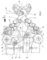
- FIG. 1 shows a view of an end wall area a cutting roller in the direction transverse to the axis of rotation the roller seen with the tool holder in the extended position and
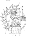
- Figure 1 is a plan view of the end wall of the roller Tool carriers swung in, partially cut.
- a cutting roller 1 is shown, on the end faces 2 bearing eyes 3 for the pivotable articulation of tool carriers 4 and 5 are defined.
- the tool carrier 4 and 5 are pivotable about the pivot axes 6 and 7 and each carry cutting chisels, which are designated 8.
- the upper of the two pivotable tool carrier 4 carries Mouth 9, which is a hook-shaped locking member for one Locking bolt 10 represents, the axis 11 of the jaw opening of the mouth 9 arranged inclined to the tool carrier 4 is.
- the locking bolt is thus supported in the extended position 10 on a steep flank 12 of the mouth 9, whereby the reaction forces effective in the sense of expansion can be supported safely.
- a coupling rod 15 is provided which about a pivot axis 16 pivotally engages the tool carrier 5.
- the other end the coupling rod is pivotable about the pivot axis 17 a bearing eye 18 of the tool carrier 4 articulated.
- FIG. 2 thus shows a view of the end wall 2 of FIG Cutting roller 1 in the direction of arrow II of Figure 1, wherein however, the tool carriers 4 and 5 in their starting position were pivoted in, whereby the locking bolt 10 except Engagement reached and pivoted towards the edge of the cutting roller becomes.
Landscapes
- Engineering & Computer Science (AREA)
- Mining & Mineral Resources (AREA)
- Mechanical Engineering (AREA)
- Life Sciences & Earth Sciences (AREA)
- General Life Sciences & Earth Sciences (AREA)
- Geochemistry & Mineralogy (AREA)
- Geology (AREA)
- Perforating, Stamping-Out Or Severing By Means Other Than Cutting (AREA)
- Treatment Of Fiber Materials (AREA)
- Harvester Elements (AREA)
- Control And Other Processes For Unpacking Of Materials (AREA)
- Nonmetal Cutting Devices (AREA)
- Shearing Machines (AREA)
- Pens And Brushes (AREA)
- Crushing And Grinding (AREA)
- Road Repair (AREA)
- Knives (AREA)
- Earth Drilling (AREA)
Description
Claims (5)
- Schräm- oder Schneidwalze (1) mit veränderbarer Schneidbreite, bei welcher an wenigstens einer seitlichen Stirnfläche (2) der Walze quer zur Achse der Schräm- oder Schneidwalze (1) zwei schwenkbare Werkzeugträger (4, 5) für die Aufnahme von Schneid- oder Schrämwerkzeugen angeordnet sind, dadurch gekennzeichnet, daß einer der Werkzeugträger einen Verriegelungsbolzen (10) trägt, welcher in ausgefahrener Stellung der Werkzeugträger (4, 5) mit einem hakenförmigen Verriegelungsglied des anderen Werkzeugträgers zusammenwirkt.
- Schräm- oder Schneidwalze nach Anspruch 1, dadurch gekennzeichnet, daß der Verriegelungsbolzen (10) sich im wesentlichen parallel zur Schwenkachse (7) des Werkzeugträgers (5) erstreckt und daß das hakenförmige Verriegelungsglied von einem dem Verriegelungsbolzen (10) zugewandten Maul (9) des anderen Werkzeugträgers (4) gebildet ist.
- Schräm- oder Schneidwalze nach Anspruch 2, dadurch gekennzeichnet, daß die Maulöffnung in Richtung zur Schwenkachse des Werkzeugträgers geneigt angeordnet ist.
- Schräm- oder Schneidwalze nach Anspruch 1, 2 oder 3, dadurch gekennzeichnet, daß die Werkzeugträger (4, 5) durch eine Koppelstange (15) zu gemeinsamer Verschwenkung verbunden sind.
- Schräm- oder Schneidwalze nach einem der Ansprüche 1 bis 4, dadurch gekennzeichnet, daß die Werkzeugträger (4, 5) jeweils mit einem hydraulischen Zylinderkolbenaggregat (13) verbunden sind, welches an der Schräm- oder Schneidwalze (1) und außerhalb der Schwenkachse (6, 7) der Werkzeugträger (4, 5) angelenkt ist.
Applications Claiming Priority (3)
| Application Number | Priority Date | Filing Date | Title |
|---|---|---|---|
| AT0014597A AT405318B (de) | 1997-01-30 | 1997-01-30 | Schräm- oder schneidwalze mit veränderbarer schneidbreite |
| AT14597 | 1997-01-30 | ||
| PCT/AT1998/000017 WO1998034010A1 (de) | 1997-01-30 | 1998-01-28 | Schräm- oder schneidwalze mit veränderbarer schneidbreite |
Publications (2)
| Publication Number | Publication Date |
|---|---|
| EP0960264A1 EP0960264A1 (de) | 1999-12-01 |
| EP0960264B1 true EP0960264B1 (de) | 2001-03-21 |
Family
ID=3482728
Family Applications (1)
| Application Number | Title | Priority Date | Filing Date |
|---|---|---|---|
| EP98901237A Expired - Lifetime EP0960264B1 (de) | 1997-01-30 | 1998-01-28 | Schräm- oder schneidwalze mit veränderbarer schneidbreite |
Country Status (7)
| Country | Link |
|---|---|
| US (1) | US6244664B1 (de) |
| EP (1) | EP0960264B1 (de) |
| AT (2) | AT405318B (de) |
| AU (1) | AU733961B2 (de) |
| DE (1) | DE59800562D1 (de) |
| WO (1) | WO1998034010A1 (de) |
| ZA (1) | ZA9710828B (de) |
Families Citing this family (8)
| Publication number | Priority date | Publication date | Assignee | Title |
|---|---|---|---|---|
| BE1014047A3 (fr) * | 2001-03-12 | 2003-03-04 | Halliburton Energy Serv Inc | Elargisseur de trou de forage. |
| US6857706B2 (en) * | 2001-12-10 | 2005-02-22 | Placer Dome Technical Services Limited | Mining method for steeply dipping ore bodies |
| US6886633B2 (en) | 2002-10-04 | 2005-05-03 | Security Dbs Nv/Sa | Bore hole underreamer |
| US6929076B2 (en) * | 2002-10-04 | 2005-08-16 | Security Dbs Nv/Sa | Bore hole underreamer having extendible cutting arms |
| US7695071B2 (en) * | 2002-10-15 | 2010-04-13 | Minister Of Natural Resources | Automated excavation machine |
| US7658241B2 (en) * | 2004-04-21 | 2010-02-09 | Security Dbs Nv/Sa | Underreaming and stabilizing tool and method for its use |
| US7192093B2 (en) * | 2004-04-23 | 2007-03-20 | Placer Dome Technical Services Limited | Excavation apparatus and method |
| WO2005124094A1 (fr) * | 2004-06-09 | 2005-12-29 | Halliburton Energy Services N.V. | Outil d’elargissement et de stabilisation a mettre en oeuvre dans un trou de forage |
Family Cites Families (8)
| Publication number | Priority date | Publication date | Assignee | Title |
|---|---|---|---|---|
| US334642A (en) * | 1886-01-19 | clerc | ||
| US2745650A (en) * | 1954-12-16 | 1956-05-15 | Goodman Mfg Co | Contractible boring head for mining machines |
| GB991569A (en) * | 1962-06-02 | 1965-05-12 | Mavor & Coulson Ltd | Improvements relating to cutter drums for mining coal and other minerals |
| US3285667A (en) * | 1964-01-29 | 1966-11-15 | Westinghouse Air Brake Co | Retractible boring head for mining machine |
| US3730593A (en) | 1971-06-21 | 1973-05-01 | Nat Mine Service Co | Continuous mining machine |
| US4172616A (en) * | 1978-01-31 | 1979-10-30 | Coaltex, Inc. | Cutting head with self-contained power source |
| US4177866A (en) | 1978-05-30 | 1979-12-11 | Dresser Industries, Inc. | System for boring raises having portions of different diameters |
| AT388776B (de) * | 1987-10-29 | 1989-08-25 | Voest Alpine Ag | Schraem- oder schneidwalze |
-
1997
- 1997-01-30 AT AT0014597A patent/AT405318B/de not_active IP Right Cessation
- 1997-12-02 ZA ZA9710828A patent/ZA9710828B/xx unknown
-
1998
- 1998-01-28 EP EP98901237A patent/EP0960264B1/de not_active Expired - Lifetime
- 1998-01-28 US US09/355,614 patent/US6244664B1/en not_active Expired - Lifetime
- 1998-01-28 AU AU57404/98A patent/AU733961B2/en not_active Ceased
- 1998-01-28 AT AT98901237T patent/ATE199961T1/de not_active IP Right Cessation
- 1998-01-28 WO PCT/AT1998/000017 patent/WO1998034010A1/de not_active Ceased
- 1998-01-28 DE DE59800562T patent/DE59800562D1/de not_active Expired - Fee Related
Also Published As
| Publication number | Publication date |
|---|---|
| AT405318B (de) | 1999-07-26 |
| ZA9710828B (en) | 1998-06-23 |
| ATE199961T1 (de) | 2001-04-15 |
| US6244664B1 (en) | 2001-06-12 |
| DE59800562D1 (de) | 2001-04-26 |
| ATA14597A (de) | 1998-11-15 |
| AU5740498A (en) | 1998-08-25 |
| AU733961B2 (en) | 2001-05-31 |
| WO1998034010A1 (de) | 1998-08-06 |
| EP0960264A1 (de) | 1999-12-01 |
Similar Documents
| Publication | Publication Date | Title |
|---|---|---|
| DE69320021T2 (de) | Bruchvorrichtung | |
| AT506502B1 (de) | Vortriebsmaschine mit bohrkopf aus diskenwerkzeugen | |
| DE69020527T2 (de) | Abbrucharbeitsgerät für einen Hydraulikbagger. | |
| EP0960264B1 (de) | Schräm- oder schneidwalze mit veränderbarer schneidbreite | |
| DE4134560A1 (de) | Hartmetallkrone und meissel | |
| DE3002115A1 (de) | Saegekette fuer motorkettensaegen | |
| DE2229940B1 (de) | Hydraulisch betaetigtes geraet zum mechanischen zerlegen von gestein | |
| EP1719876A1 (de) | Ausbaugestell für eine untertägige Strecke | |
| DE3531384C2 (de) | ||
| DE3626986C2 (de) | ||
| DE2451290A1 (de) | Schere, insbesondere flach- oder stabstahlschere | |
| EP0181454A2 (de) | Schneepflug | |
| DE3504761A1 (de) | Ausleger fuer bohrmaschinen | |
| EP1329414B1 (de) | Materialumschlaggerät | |
| DE3011100C3 (de) | Hobelanlage | |
| DE2819082C2 (de) | Hobel | |
| DE2217830B2 (de) | Schildausbaugestell | |
| DE3312441A1 (de) | Uebergabestation in einer foerderbandstrasse | |
| DE3447192C2 (de) | Hobel für die untertägige Gewinnung | |
| DE2153496C3 (de) | Schreitendes Strebausbaugestell | |
| DE3000275A1 (de) | Universal-arbeitsmaschine, insbesondere zum streckenvortrieb in gruben | |
| EP0498285A1 (de) | Anbauschere | |
| AT391349B (de) | Schraemmaschine | |
| DE2719161C3 (de) | Kohlenhobelmittelteil | |
| DE2451747B1 (de) | Schildartiges ausbaugestell |
Legal Events
| Date | Code | Title | Description |
|---|---|---|---|
| PUAI | Public reference made under article 153(3) epc to a published international application that has entered the european phase |
Free format text: ORIGINAL CODE: 0009012 |
|
| 17P | Request for examination filed |
Effective date: 19990712 |
|
| AK | Designated contracting states |
Kind code of ref document: A1 Designated state(s): AT DE GB |
|
| RAP1 | Party data changed (applicant data changed or rights of an application transferred) |
Owner name: VOEST-ALPINE BERGTECHNIK GESELLSCHAFT M.B.H |
|
| GRAG | Despatch of communication of intention to grant |
Free format text: ORIGINAL CODE: EPIDOS AGRA |
|
| 17Q | First examination report despatched |
Effective date: 20000511 |
|
| GRAG | Despatch of communication of intention to grant |
Free format text: ORIGINAL CODE: EPIDOS AGRA |
|
| GRAH | Despatch of communication of intention to grant a patent |
Free format text: ORIGINAL CODE: EPIDOS IGRA |
|
| GRAH | Despatch of communication of intention to grant a patent |
Free format text: ORIGINAL CODE: EPIDOS IGRA |
|
| GRAA | (expected) grant |
Free format text: ORIGINAL CODE: 0009210 |
|
| AK | Designated contracting states |
Kind code of ref document: B1 Designated state(s): AT DE GB |
|
| REF | Corresponds to: |
Ref document number: 199961 Country of ref document: AT Date of ref document: 20010415 Kind code of ref document: T |
|
| REF | Corresponds to: |
Ref document number: 59800562 Country of ref document: DE Date of ref document: 20010426 |
|
| GBT | Gb: translation of ep patent filed (gb section 77(6)(a)/1977) |
Effective date: 20010619 |
|
| EN | Fr: translation not filed | ||
| REG | Reference to a national code |
Ref country code: GB Ref legal event code: IF02 |
|
| PLBE | No opposition filed within time limit |
Free format text: ORIGINAL CODE: 0009261 |
|
| STAA | Information on the status of an ep patent application or granted ep patent |
Free format text: STATUS: NO OPPOSITION FILED WITHIN TIME LIMIT |
|
| PG25 | Lapsed in a contracting state [announced via postgrant information from national office to epo] |
Ref country code: GB Free format text: LAPSE BECAUSE OF NON-PAYMENT OF DUE FEES Effective date: 20020128 |
|
| 26N | No opposition filed | ||
| GBPC | Gb: european patent ceased through non-payment of renewal fee |
Effective date: 20020128 |
|
| PGFP | Annual fee paid to national office [announced via postgrant information from national office to epo] |
Ref country code: AT Payment date: 20090115 Year of fee payment: 12 |
|
| PGFP | Annual fee paid to national office [announced via postgrant information from national office to epo] |
Ref country code: DE Payment date: 20090122 Year of fee payment: 12 |
|
| PG25 | Lapsed in a contracting state [announced via postgrant information from national office to epo] |
Ref country code: DE Free format text: LAPSE BECAUSE OF NON-PAYMENT OF DUE FEES Effective date: 20100803 Ref country code: AT Free format text: LAPSE BECAUSE OF NON-PAYMENT OF DUE FEES Effective date: 20100128 |