EP0960298B1 - Raccord d'extremite tubulaire - Google Patents
Raccord d'extremite tubulaire Download PDFInfo
- Publication number
- EP0960298B1 EP0960298B1 EP98907462A EP98907462A EP0960298B1 EP 0960298 B1 EP0960298 B1 EP 0960298B1 EP 98907462 A EP98907462 A EP 98907462A EP 98907462 A EP98907462 A EP 98907462A EP 0960298 B1 EP0960298 B1 EP 0960298B1
- Authority
- EP
- European Patent Office
- Prior art keywords
- cylinder
- segments
- arrangement according
- segment
- end connection
- Prior art date
- Legal status (The legal status is an assumption and is not a legal conclusion. Google has not performed a legal analysis and makes no representation as to the accuracy of the status listed.)
- Expired - Lifetime
Links
- 239000002131 composite material Substances 0.000 claims description 29
- 125000006850 spacer group Chemical group 0.000 claims description 14
- 229910052751 metal Inorganic materials 0.000 claims description 9
- 239000002184 metal Substances 0.000 claims description 9
- 238000000034 method Methods 0.000 claims description 6
- 238000009730 filament winding Methods 0.000 claims description 5
- 238000000926 separation method Methods 0.000 claims description 4
- 239000000945 filler Substances 0.000 claims description 3
- 238000009787 hand lay-up Methods 0.000 claims description 3
- 238000004519 manufacturing process Methods 0.000 claims description 3
- 230000000295 complement effect Effects 0.000 claims description 2
- 230000008602 contraction Effects 0.000 claims description 2
- 230000000712 assembly Effects 0.000 claims 2
- 238000000429 assembly Methods 0.000 claims 2
- 239000007788 liquid Substances 0.000 claims 2
- 238000005553 drilling Methods 0.000 description 9
- 229910000831 Steel Inorganic materials 0.000 description 8
- 239000010959 steel Substances 0.000 description 8
- 230000033001 locomotion Effects 0.000 description 6
- 230000007613 environmental effect Effects 0.000 description 4
- 239000011347 resin Substances 0.000 description 4
- 229920005989 resin Polymers 0.000 description 4
- 239000000853 adhesive Substances 0.000 description 3
- 230000001070 adhesive effect Effects 0.000 description 3
- 238000005304 joining Methods 0.000 description 3
- 230000008646 thermal stress Effects 0.000 description 3
- XLYOFNOQVPJJNP-UHFFFAOYSA-N water Substances O XLYOFNOQVPJJNP-UHFFFAOYSA-N 0.000 description 3
- 238000005452 bending Methods 0.000 description 2
- 150000001875 compounds Chemical class 0.000 description 2
- 238000006073 displacement reaction Methods 0.000 description 2
- 238000007667 floating Methods 0.000 description 2
- 238000007654 immersion Methods 0.000 description 2
- 239000000463 material Substances 0.000 description 2
- 238000004382 potting Methods 0.000 description 2
- 230000035882 stress Effects 0.000 description 2
- RTAQQCXQSZGOHL-UHFFFAOYSA-N Titanium Chemical compound [Ti] RTAQQCXQSZGOHL-UHFFFAOYSA-N 0.000 description 1
- 238000005299 abrasion Methods 0.000 description 1
- 239000011157 advanced composite material Substances 0.000 description 1
- 229910052782 aluminium Inorganic materials 0.000 description 1
- XAGFODPZIPBFFR-UHFFFAOYSA-N aluminium Chemical compound [Al] XAGFODPZIPBFFR-UHFFFAOYSA-N 0.000 description 1
- 230000015572 biosynthetic process Effects 0.000 description 1
- 238000009734 composite fabrication Methods 0.000 description 1
- 230000007797 corrosion Effects 0.000 description 1
- 238000005260 corrosion Methods 0.000 description 1
- 238000005516 engineering process Methods 0.000 description 1
- 239000000835 fiber Substances 0.000 description 1
- 239000012530 fluid Substances 0.000 description 1
- 230000002706 hydrostatic effect Effects 0.000 description 1
- 238000003780 insertion Methods 0.000 description 1
- 230000037431 insertion Effects 0.000 description 1
- 239000006082 mold release agent Substances 0.000 description 1
- 230000036316 preload Effects 0.000 description 1
- 230000002028 premature Effects 0.000 description 1
- 239000010936 titanium Substances 0.000 description 1
- 229910052719 titanium Inorganic materials 0.000 description 1
- 239000013585 weight reducing agent Substances 0.000 description 1
- 238000004804 winding Methods 0.000 description 1
Images


Classifications
-
- E—FIXED CONSTRUCTIONS
- E21—EARTH OR ROCK DRILLING; MINING
- E21B—EARTH OR ROCK DRILLING; OBTAINING OIL, GAS, WATER, SOLUBLE OR MELTABLE MATERIALS OR A SLURRY OF MINERALS FROM WELLS
- E21B17/00—Drilling rods or pipes; Flexible drill strings; Kellies; Drill collars; Sucker rods; Cables; Casings; Tubings
- E21B17/02—Couplings; joints
- E21B17/08—Casing joints
- E21B17/085—Riser connections
-
- E—FIXED CONSTRUCTIONS
- E21—EARTH OR ROCK DRILLING; MINING
- E21B—EARTH OR ROCK DRILLING; OBTAINING OIL, GAS, WATER, SOLUBLE OR MELTABLE MATERIALS OR A SLURRY OF MINERALS FROM WELLS
- E21B17/00—Drilling rods or pipes; Flexible drill strings; Kellies; Drill collars; Sucker rods; Cables; Casings; Tubings
- E21B17/01—Risers
-
- F—MECHANICAL ENGINEERING; LIGHTING; HEATING; WEAPONS; BLASTING
- F16—ENGINEERING ELEMENTS AND UNITS; GENERAL MEASURES FOR PRODUCING AND MAINTAINING EFFECTIVE FUNCTIONING OF MACHINES OR INSTALLATIONS; THERMAL INSULATION IN GENERAL
- F16B—DEVICES FOR FASTENING OR SECURING CONSTRUCTIONAL ELEMENTS OR MACHINE PARTS TOGETHER, e.g. NAILS, BOLTS, CIRCLIPS, CLAMPS, CLIPS OR WEDGES; JOINTS OR JOINTING
- F16B2200/00—Constructional details of connections not covered for in other groups of this subclass
- F16B2200/40—Clamping arrangements where clamping parts are received in recesses of elements to be connected
-
- F—MECHANICAL ENGINEERING; LIGHTING; HEATING; WEAPONS; BLASTING
- F16—ENGINEERING ELEMENTS AND UNITS; GENERAL MEASURES FOR PRODUCING AND MAINTAINING EFFECTIVE FUNCTIONING OF MACHINES OR INSTALLATIONS; THERMAL INSULATION IN GENERAL
- F16B—DEVICES FOR FASTENING OR SECURING CONSTRUCTIONAL ELEMENTS OR MACHINE PARTS TOGETHER, e.g. NAILS, BOLTS, CIRCLIPS, CLAMPS, CLIPS OR WEDGES; JOINTS OR JOINTING
- F16B2200/00—Constructional details of connections not covered for in other groups of this subclass
- F16B2200/40—Clamping arrangements where clamping parts are received in recesses of elements to be connected
- F16B2200/403—Threaded clamping parts
-
- Y—GENERAL TAGGING OF NEW TECHNOLOGICAL DEVELOPMENTS; GENERAL TAGGING OF CROSS-SECTIONAL TECHNOLOGIES SPANNING OVER SEVERAL SECTIONS OF THE IPC; TECHNICAL SUBJECTS COVERED BY FORMER USPC CROSS-REFERENCE ART COLLECTIONS [XRACs] AND DIGESTS
- Y10—TECHNICAL SUBJECTS COVERED BY FORMER USPC
- Y10T—TECHNICAL SUBJECTS COVERED BY FORMER US CLASSIFICATION
- Y10T428/00—Stock material or miscellaneous articles
- Y10T428/13—Hollow or container type article [e.g., tube, vase, etc.]
- Y10T428/1352—Polymer or resin containing [i.e., natural or synthetic]
- Y10T428/139—Open-ended, self-supporting conduit, cylinder, or tube-type article
-
- Y—GENERAL TAGGING OF NEW TECHNOLOGICAL DEVELOPMENTS; GENERAL TAGGING OF CROSS-SECTIONAL TECHNOLOGIES SPANNING OVER SEVERAL SECTIONS OF THE IPC; TECHNICAL SUBJECTS COVERED BY FORMER USPC CROSS-REFERENCE ART COLLECTIONS [XRACs] AND DIGESTS
- Y10—TECHNICAL SUBJECTS COVERED BY FORMER USPC
- Y10T—TECHNICAL SUBJECTS COVERED BY FORMER US CLASSIFICATION
- Y10T428/00—Stock material or miscellaneous articles
- Y10T428/13—Hollow or container type article [e.g., tube, vase, etc.]
- Y10T428/1352—Polymer or resin containing [i.e., natural or synthetic]
- Y10T428/139—Open-ended, self-supporting conduit, cylinder, or tube-type article
- Y10T428/1393—Multilayer [continuous layer]
Definitions
- the invention in general relates to composite structures and more particularly to tubular composites with an end connection.
- composite materials in place of metal for various structures is desirable for many reasons, including weight reduction, corrosion resistance, durability and increased strength.
- One type of structure which finds use in a variety of applications is a tube, or cylinder, which must be joined to another similar or dissimilar structure, at either or both ends. Accordingly, an end piece, of a material such as metal, is provided as the cylinder termination for the joining process.
- the use of adhesives for bonding the metal end piece to the composite cylinder may be less than satisfactory under certain conditions, particularly in the presence of large bending moments or axial loads which leads to debonding. Extreme environmental conditions such as immersion in water can weaken the bond. Large temperature changes can cause joint failure due to coefficient of thermal expansion mismatch induced thermal stresses.
- a composite cylinder has an end which is wound over, and bonded to, a contoured end piece which is of such geometrical shape that it is locked in place.
- This geometrical lock type joint typically has a bonded interface between the composite and end piece, however under large load conditions the bond may fail, allowing undesired relative movement between the composite and the end piece. Or it may become highly loaded during fabrication or use due to temperature changes. As with a conventional bonded joint when the bond fails an undesirable gap may open up.
- the present invention provides a solution to the end joint problem so as to allow for a structure which can accommodate relatively high axial loads and bending moments without failure of the joint or without excessive movement.
- FR-A-1 523 724 describes an end connection for a tube.
- the end connection comprising a sleeve which is held in connection with an undeformed outer surface of the tube by a bisected ring.
- the end connection can be connected by to a further tube by a further bisected ring.
- a composite-to-end connection arrangement in accordance with the present invention includes a hollow cylinder of composite material which extends along a central longitudinal axis.
- An end connection assembly having a plurality of segments is provided, with at least one of the segments being in contact with the inner surface of the cylinder at an end portion. In one preferred embodiment two segments are in contact with the inner surface.
- the end of the cylinder is formed about the segment, or segments, so as to assume the contour thereof, the contour having a predetermined shape so as to prevent withdrawal of the segment, or segments from the cylinder.
- the arrangement includes spacer means, separating the segments and forcing one or both into intimate contact with the inner contoured surface of the cylinder to limit axial movement of the assembly due to a predetermined load condition.
- spacer means are positioned between two segments.
- Fig. 1 illustrates one of many applications for the present invention.
- Figs. 2A to 2C illustrate a geometric lock joint of the prior art.
- Figs. 3A to 3C illustrate the principle involved in the present invention.
- Figs. 4A to 4G illustrate various embodiments of the present invention wherein segments of an end connection assembly are longitudinally arranged.
- Fig. 5 illustrates an embodiment of the invention wherein segments of an end connection assembly are coaxially arranged.
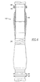
- Fig. 6 illustrates a marine riser section made in accordance with the present invention.
- a riser arrangement 10 made up of a plurality of riser sections 12 extends from a floating platform 14 at the surface to drilling equipment 16, such as a blowout preventer, located on the bed 18 of a body of water.
- the primary function of the riser 10 is to guide drill pipe and tools to the well bore and to provide a return path for drilling mud which is pumped down the center of the drill pipe to cool and lubricate the drill bit, flush tailings out of the bore and balance the hydrostatic pressure of the formation being drilled through.
- Drilling risers are generally of medium strength steel which create significant weight loads for the floating platform 14. Accordingly, advanced composite drilling risers are being considered as a replacement for steel thereby significantly reducing the deck weight of the riser system, and allowing a greater number of riser sections to be carried, to extend the drilling capabilities to greater depths.
- Fig. 2A illustrates, in cross-sectional view, an end connection for a composite cylinder in an arrangement which prevents the connection from being withdrawn from the composite cylinder.
- the structural arrangement includes a composite cylinder 20 which extends along a central longitudinal axis C. Cylinder 20 has an end portion 21 formed about an internal ring 22, such as by filament winding, to thereby conform to the contour of the ring 22.
- the contour of the ring 22 is defined by hyperboloidal surface portions 24 and 25 on either side of an isotensoidal, or circular arc surface portion 26, which defines the maximum diameter of the ring 22.
- the arrangement typically incorporates an optional adhesive bond 28 between the ring 22 and the inner surface of the cylinder end 21.
- an elevated temperature cure composite If an elevated temperature cure composite is used, its coefficient of thermal expansion needs to be tailored by varying the fiber type and orientation during winding so that it matches that of the material being wound over, typically steel, aluminum or titanium. A large coefficient of thermal expansion mismatch yields high residual thermal stresses in the bondline between the composite and metallic ring which may lead to debonding as the parts cool down from an elevated temperature. This is illustrated in Fig 2B by debonded portions 30 and 31. A similar gap can occur if there is not adhesive at the interface with temperature environmental changes.
- Complete bond failure results in a relatively large displacement, d, between the cylinder 20 and the initial position of ring 22, when subjected to an axial load represented by arrow 36.
- d a relatively large displacement
- arrow 36 an axial load
- large relative motions will cause damage to the composite cylinder 20 due to fretting and abrasion.
- the relative motion will also damage an inner liner, if used.
- Figs. 3A to 3C serve to illustrate the basic concept of one embodiment of the present invention.
- a cylinder 40 of composite material extends along, and surrounds a central longitudinal axis C.
- An end 41 of the cylinder 40 is formed around an end connection assembly 42, having a contour which will prevent its withdrawal from the cylinder.
- the forming may be accomplished by a variety of composite fabrication processes such as filament winding, tape laying, roll wrapping or hand layup, to name a few.
- the end connection assembly may be of a metal such as steel and its contour may be as previously described in Fig. 2A with respect to ring 22.
- the end connection assembly however in the present invention includes a plurality of longitudinally displaced segments, two, 42a and 42b, being shown by way of example.
- the two segments 42a and 42b initially touch one another such as at the point of maximum outside diameter and one, or both, of the segments are free to move in an axial direction. That is, by use of a mold release agent covering their surface, they are not bonded to the inner surface of the cylinder.
- the two segments 42a and 42b are relatively forced apart, as indicated by arrows 44 and 45 in Fig. 3B, leaving a gap g between them.
- the separation process may be accomplished by applying an external force to the outermost segment 42b, while holding segment 42a immobile or by tooling which contacts and separates both segments 42a and 42b to preload the composite-metal interface.
- a spacer 46 is inserted into the gap between the ends of segments 42a and 42b, the external separating force is removed, and the restoring force, as indicated by arrows 47 and 48, maintain the spacer 46 in position.
- a portion, such as 49, of one of the segments extends past the end of the composite cylinder.
- An external connector may then be coupled to this extended portion for joining the cylinder to another structure.
- FIG. 4A to 4G Several embodiments of the invention using an end connection assembly with longitudinally arranged segments are illustrated in Figs. 4A to 4G.
- Fig. 4A illustrates a composite cylinder 50, having an end portion 51, and similar to that of Fig 3A.
- An end connection assembly 54 includes sections 54a and 54b each having a respective tapered end 58a and 58b.
- a spacer in the form of wedge 60 conforming to the tapered ends 58a and 58b is positioned between segments- 54a and 54b to separate them and force them into intimate contact with the inner contoured surface of the cylinder 50 to limit axial movement of the assembly 54 due to a predetermined load such as an externally applied axial load or a thermal load which may cause a gap due to differential thermal contraction of parts.
- Wedge 60 may be formed in a plurality of circumferential sections for ease of insertion into the wedge shaped gap between segments 54a and 54b.
- a circumferential overwrap 62 may be applied over the end of the cylinder 50.
- the end connection assembly 64 includes segments 64a and 64b.
- Counterbores, or access groove 66 near the end 68a of segment 64a accommodates, and allows access to a plurality of jack screws 70.
- These jack screws 70 are circumferentially arranged and protrude through the end 68a and bear against the end 68b of segment 64b. Advancement of the jack screws 70 applies a separating force to the segments 64a and 64b to accomplish the desired function.
- segments 74a and 74b of end connection assembly 74 meet in a tongue-in-groove relationship and are forced apart by means of hydraulic pressure. More particularly, a fluid such as resin is hydraulically introduced into passageway 76 thus forcing the segments 74a and 74b apart. After a sufficient passage of time, injected resin would attain a hardened condition in the cavity 78, formed as a result of the separation process, and act as a separating spacer means. If desired, a resin or potting compound may be injected into the resulting surrounding annulus 80 via passageway 82.
- the end connection assembly 84 includes segments 84a and 84b having respective overlapping ends 86a and 86b.
- a split ring spacer 88 in several parts, may be inserted into the gap and the annulus 90 may be filled with a resin or potting compound via passageway 92.
- the end connection assembly 94 of Fig. 4E has the separation between segments 94a and 94b filled in by means of a plurality of wedge inserts 96.
- Each wedge insert includes a lower flange 98 through which a series of fasteners 100 secure the wedge to the respective ends 102a and 102b of segments 94a and 94b, said ends being shaped to conform to the shape of the wedge 96.
- Fig. 4F The embodiment of Fig. 4F is somewhat similar to that of Fig. 4A in its inclusion of a plurality of tapered wedges 104 separating and forcing apart segments 106a and 106b of end connection assembly 106.
- the wedges are maintained in position by means of fasteners 110 which pass through the end of cylinder 50 as well as the circumferential overwrap 62.
- fasteners 110 which pass through the end of cylinder 50 as well as the circumferential overwrap 62.
- the structure may be weakened somewhat by the inclusion of holes in the composite, the arrangement may be used for low strength requirements.
- segments 112a and 112b of end connection assembly 112 have complementary screw threads which engage one another, as indicated by numeral 114, so that relative rotation of the segments will cause them to move axially relative to one another and maintain the segments 112a and 112b in a forced apart condition.
- FIG. 5 Another embodiment of the invention is illustrated in Fig. 5.
- a composite cylinder 120 having an end portion 121, surrounds a central longitudinal axis C.
- An end connection assembly 122 includes a plurality of segments, two, 122a and 122b, being shown by way of example. The segments of Fig. 5 are arranged such that one segment, 122a, is located against the inner surface of cylinder 120 while the other segment 122b contacts the outer surface of cylinder 120 and surrounds the major portion of segment 122a.
- Segment 122a extends past the end of cylinder 120 and includes a projection 124. This projection is on a portion of the segment which is welded on, as indicated by weld 125, after segment 122b is placed into position. Segment 122b also includes a projection 126 such that when the segments are moved apart, a multipart spacer 128 may be inserted into the gap between the projections 124 and 126.
- a filler member 130 is positioned within the cylinder 120 adjacent segment 122a to achieve the desired contour and to eliminate any gaps in the inside diameter of the cylinder 120.
- the embodiments of the invention include a feature wherein a portion of one of the segments extends past the end of the composite cylinder.
- An external connector such as a flange, threaded connector, radially dogged connector, or the like, may then be coupled to this extended portion for joining the cylinder to another structure.
- a typical marine riser 140 including end connection arrangements 142 at both ends and constructed in accordance with the teachings herein.
- an end connection assembly 144 having segments made of a metal such as steel
- an external connector such as steel flange 146 may be welded to the exposed ends of the segments at either end of the riser section 140.
- the flanges 146 may then be bolted to the flanges 146' of respective adjacent riser sections, with the process being repeated, thus resulting in a light weight marine riser system.
Landscapes
- Engineering & Computer Science (AREA)
- Life Sciences & Earth Sciences (AREA)
- Geology (AREA)
- Mining & Mineral Resources (AREA)
- Mechanical Engineering (AREA)
- Physics & Mathematics (AREA)
- Environmental & Geological Engineering (AREA)
- Fluid Mechanics (AREA)
- General Life Sciences & Earth Sciences (AREA)
- Geochemistry & Mineralogy (AREA)
- Mutual Connection Of Rods And Tubes (AREA)
- Earth Drilling (AREA)
Claims (24)
- Agencement de raccord d'extrémité composite comprenant :(A) un cylindre creux (40, 50, 120) en matériau composite s'étendant le long d'un axe longitudinal central ;(B) un ensemble raccord d'extrémité (42, 52, 122) ayant une pluralité de segments (42a, 42b, 54a, 54b, 122a, 122b), dont l'un au moins (42a, 54a, 122a) est en contact avec la surface interne dudit cylindre à une extrémité de celui-ci ;(C) ladite extrémité dudit cylindre étant formée autour dudit segment (42 a, 54 a, 122 a) pour assurer le contour de celui-ci, ledit contour ayant une forme prédéterminée de telle sorte à empêcher le retrait dudit segment dudit cylindre et(D) des moyens d'espacement (46, 60, 128) séparant au moins deux desdits segments et forçant au moins un d'entre eux à être en contact étroit avec la surface profilée interne dudit cylindre, pour limiter le mouvement axial dudit ensemble en raison d'une charge prédéterminée, ou bien pour combler tout vide ou séparation entre le cylindre composite et les segments qui pourrait survenir en raison de la contraction thermique.
- Agencement selon la revendication 1 dans lequel :(A) ledit cylindre composite est formé autour dudit segment (42 a, 54 a, 122 a) par un procédé choisi parmi le groupe comprenant l'enroulement filamentaire, le rubanage, l'emballage en rouleau et le laminage à la main.
- Agencement selon la revendication 1 ou la revendication 2, dans lequel :(A) ledit ensemble raccord d'extrémité comprend deux segments (122a, 122b), l'un à l'intérieur dudit cylindre (122a) et l'autre à l'extérieur dudit cylindre (122b).
- Agencement selon la revendication 3, dans lequel :(A) le segment extérieur est coaxial au segment intérieur et entoure celui-ci.
- Agencement selon l'une quelconque des revendications précédentes, dans lequel :(A) ledit contour prédéterminé est hyperboloïdal, et qui comprend(B) un élément de remplissage (130) positionné à l'intérieur dudit cylindre adjacent audit segment intérieur ;(C) ledit élément de remplissage possédant un contour hyperboloïdal.
- Agencement selon l'une quelconque des revendications précédentes, dans lequel :(A) un autre desdits ensembles raccord d'extrémité est positionné au niveau de l'extrémité opposée dudit cylindre.
- Agencement selon la revendication 1 dans lequel :la pluralité de segments est disposée longitudinalement de façon coaxiale à l'axe longitudinal central.
- Agencement selon la revendication 7, dans lequel :(A) ledit cylindre composite est formé autour desdits segments disposés longitudinalement par un processus choisi parmi le groupe comprenant l'enroulement filamentaire, le rubanage, l'emballage en rouleau et le laminage à la main.
- Agencement selon la revendication 7 ou la revendication 8 qui comprend :(A) une surenveloppe circonférentielle, couvrant ladite extrémité dudit cylindre.
- Agencement selon l'une quelconque des revendications 7 à 9, dans lequel :(A) ledit contour est défini par deux hyperboloïdes joints.
- Agencement selon la revendication 10, dans lequel :(A) lesdits hyperboloïdes sont joints par un contour isotensoïdal ou incurvé.
- Agencement selon l'une quelconque des revendications 7 à 11, dans lequel :(A) ledit ensemble raccord d'extrémité possède deux segments ayant des extrémités qui sont initialement en contact l'une avec l'autre au niveau d'une zone de diamètre maximum de ladite extrémité dudit cylindre.
- Agencement selon l'une quelconque des revendications 7 à 12, dans lequel :(A) ledit ensemble raccord d'extrémité possède des premiers et seconds segments (54a, 54b, 94a, 94b, 106a, 106b) dont les extrémités se font face ;(B) lesdites extrémités étant coniques ; et dans lequel(C) lesdits moyens d'espacement comprennent une cale (60, 96, 104) ayant des faces coniques complémentaires des extrémités coniques desdits segments.
- Agencement selon la revendication 13, dans lequel :(A) ladite cale comprend une bride (98) fixée auxdits premiers et seconds segments.
- Agencement selon la revendication 13, dans lequel :(A) ladite cale possède une ouverture traversante ;(B) ladite extrémité dudit cylindre possède une ouverture traversante et qui comprend(C) une fixation (110) qui s'étend à travers lesdites ouvertures dans ladite cale et ladite extrémité dudit cylindre.
- Agencement selon l'une quelconque des revendications 7 à 12, dans lequel :(A) ledit ensemble raccord d'extrémité possède des premier et second segments ayant des extrémités se faisant face ;(B) ledit premier segment comprenant au moins une rainure d'accès (66) proche de l'extrémité de celui-ci ;(C) lesdits moyens d'espacement comprenant au moins une vis de calage (70) s'étendant à partir de ladite rainure à travers ladite extrémité (68a), et en contact avec l'extrémité (68b) dudit second segment pour forcer l'écartement desdits segments.
- Agencement selon l'une quelconque des revendications 7 à 12, dans lequel :(A) ledit ensemble raccord d'extrémité possède des premier et second segments (74a, 74b) ayant des extrémités se faisant face et formant une relation languette-rainure ;(B) au moins un desdits segments comprenant un passage (76) conduisant à ladite extrémité dudit segment à partir de l'intérieur dudit cylindre ;(C) lesdits moyens d'espacement sont constitués par un liquide solidifié qui est initialement introduit dans ledit passage à l'état liquide pour forcer l'écartement desdits segments.
- Agencement selon l'une quelconque des revendications 7 à 12, dans lequel :(A) ledit ensemble raccord d'extrémité possède des premier et second segments (112a, 112b) ayant des extrémités respectives dotées de filetages (114) qui s'engagent l'une dans l'autre en les vissant ;(B) lesdits moyens d'espacement sont constitués par lesdits filetages après avoir dévissé lesdits segments d'une quantité prédéterminée.
- Agencement selon l'une quelconque des revendications 7 à 15, dans lequel :(A) lesdits moyens d'espacement sont constitués par une bague à plusieurs parties.
- Agencement selon l'une quelconque des revendications précédentes, dans lequel :(A) au moins un desdits segments s'étend au-delà de ladite extrémité dudit cylindre ; et qui comprend(B) un raccord externe accouplé audit segment qui s'étend au-delà de ladite extrémité dudit cylindre.
- Agencement selon la revendication 20, dans lequel :(A) ledit segment qui s'étend au-delà de ladite extrémité dudit cylindre est en métal ; et(B) ledit raccord externe est une bride de métal soudée audit segment.
- Agencement selon l'une quelconque des revendications précédentes, dans lequel :(A) ledit cylindre est un tube prolongateur (140).
- Agencement selon la revendication 22, qui comprend :(A) des premier et second raccords externes raccordés (146) respectivement audits ensembles raccord d'extrémité au niveau des extrémités dudit cylindre.
- Procédé de fabrication d'un raccord d'extrémité pour un cylindre composite, comprenant les étapes de :(A) formation d'au moins une extrémité dudit cylindre autour d'un élément ayant un contour pour empêcher son retrait dudit cylindre et(B) préchargement dudit élément par rapport audit cylindre en forçant ledit élément pour qu'il entre en contact avec la surface interne dudit cylindre avant utilisation.
Applications Claiming Priority (3)
| Application Number | Priority Date | Filing Date | Title |
|---|---|---|---|
| US08/800,600 US5771975A (en) | 1997-02-14 | 1997-02-14 | Composite cylinder termination |
| US800600 | 1997-02-14 | ||
| PCT/US1998/002870 WO1998036202A1 (fr) | 1997-02-14 | 1998-02-12 | Raccord d'extremite tubulaire |
Publications (2)
| Publication Number | Publication Date |
|---|---|
| EP0960298A1 EP0960298A1 (fr) | 1999-12-01 |
| EP0960298B1 true EP0960298B1 (fr) | 2002-08-28 |
Family
ID=25178834
Family Applications (1)
| Application Number | Title | Priority Date | Filing Date |
|---|---|---|---|
| EP98907462A Expired - Lifetime EP0960298B1 (fr) | 1997-02-14 | 1998-02-12 | Raccord d'extremite tubulaire |
Country Status (4)
| Country | Link |
|---|---|
| US (1) | US5771975A (fr) |
| EP (1) | EP0960298B1 (fr) |
| BR (1) | BR9807385A (fr) |
| WO (1) | WO1998036202A1 (fr) |
Families Citing this family (12)
| Publication number | Priority date | Publication date | Assignee | Title |
|---|---|---|---|---|
| US6435775B1 (en) * | 2000-05-22 | 2002-08-20 | Edo Corporation, Fiber Science Division | Buoyancy system with buoyancy module seal |
| US6405762B1 (en) | 2000-06-16 | 2002-06-18 | Cooper Cameron Corporation | Composite pipe assembly and method for preparing the same |
| US6734805B2 (en) | 2000-08-07 | 2004-05-11 | Abb Vetco Gray Inc. | Composite pipe telemetry conduit |
| US7025384B2 (en) | 2000-09-08 | 2006-04-11 | Vetco Gray Inc. | Apparatus and method for securing a tubular liner in a composite pipe |
| US6632112B2 (en) | 2000-11-30 | 2003-10-14 | Edo Corporation, Fiber Science Division | Buoyancy module with external frame |
| JP4204772B2 (ja) | 2001-08-30 | 2009-01-07 | 独立行政法人科学技術振興機構 | 生体内薬物徐放材料の製造方法 |
| US6805201B2 (en) * | 2002-01-31 | 2004-10-19 | Edo Corporation, Fiber Science Division | Internal beam buoyancy system for offshore platforms |
| US7096957B2 (en) * | 2002-01-31 | 2006-08-29 | Technip Offshore, Inc. | Internal beam buoyancy system for offshore platforms |
| US20050100414A1 (en) * | 2003-11-07 | 2005-05-12 | Conocophillips Company | Composite riser with integrity monitoring apparatus and method |
| US7328747B2 (en) * | 2004-05-03 | 2008-02-12 | Edo Corporation, Fiber Science Division | Integrated buoyancy joint |
| US20060131079A1 (en) * | 2004-12-16 | 2006-06-22 | Halliburton Energy Services, Inc. | Composite motor stator |
| US7963337B2 (en) * | 2008-08-07 | 2011-06-21 | Vetco Gray Inc. | Composite enhanced metallic drilling riser system |
Family Cites Families (17)
| Publication number | Priority date | Publication date | Assignee | Title |
|---|---|---|---|---|
| FR1523724A (fr) * | 1966-05-21 | 1968-05-03 | Kloeckner Werke Ag | Joints détachables pour tubes |
| US3501173A (en) * | 1968-04-10 | 1970-03-17 | Shell Oil Co | Tubular connector for lightweight marine conductor pipe |
| US4118262A (en) * | 1976-05-21 | 1978-10-03 | Brunswick Corporation | Longitudinal load carrying method for fiber reinforced filament wound structures |
| US4097626A (en) * | 1976-06-07 | 1978-06-27 | Grafalloy Corporation | Construction for a fiber reinforced shaft |
| US4239266A (en) * | 1978-01-16 | 1980-12-16 | Bill B. Berryhill | Pipe connector apparatus |
| DE2855570C2 (de) * | 1978-12-22 | 1985-06-20 | Messerschmitt-Bölkow-Blohm GmbH, 8012 Ottobrunn | Stabförmiges Bauelement |
| US4238540A (en) * | 1979-05-29 | 1980-12-09 | Celanese Corporation | Fiber reinforced composite shaft with metallic connector sleeves mounted by connector ring interlock |
| US4236386A (en) * | 1979-05-29 | 1980-12-02 | Celanese Corporation | Fiber reinforced composite shaft with metallic connector sleeves mounted by a polygonal surface interlock |
| US4470621A (en) * | 1982-01-04 | 1984-09-11 | Hydril Company | Flexible tubular connector |
| US4634314A (en) * | 1984-06-26 | 1987-01-06 | Vetco Offshore Inc. | Composite marine riser system |
| JPH0746391B2 (ja) * | 1984-09-14 | 1995-05-17 | 株式会社日立製作所 | 図形シエ−デイング装置 |
| US4701231A (en) * | 1986-05-15 | 1987-10-20 | Westinghouse Electric Corp. | Method of forming a joint between a tubular composite and a metal ring |
| US5043217A (en) * | 1989-11-15 | 1991-08-27 | Westinghouse Electric Corp. | Composite to metal joint for torsional shafts |
| US5215413A (en) * | 1991-07-26 | 1993-06-01 | Westinghouse Electric Corp. | Composite-to-metal shaft joint |
| FR2683260B1 (fr) * | 1991-11-05 | 1995-10-20 | Aerospatiale | Tube en materiau composite pour forage et/ou transport de produits liquides ou gazeux, en particulier pour l'exploitation petroliere en mer et procede de fabrication d'un tel tube. |
| US5439323A (en) * | 1993-07-09 | 1995-08-08 | Westinghouse Electric Corporation | Rod and shell composite riser |
| US5474132A (en) * | 1994-04-28 | 1995-12-12 | Westinghouse Electric Corporation | Marine riser |
-
1997
- 1997-02-14 US US08/800,600 patent/US5771975A/en not_active Expired - Lifetime
-
1998
- 1998-02-12 BR BR9807385-0A patent/BR9807385A/pt not_active IP Right Cessation
- 1998-02-12 WO PCT/US1998/002870 patent/WO1998036202A1/fr not_active Ceased
- 1998-02-12 EP EP98907462A patent/EP0960298B1/fr not_active Expired - Lifetime
Also Published As
| Publication number | Publication date |
|---|---|
| WO1998036202A1 (fr) | 1998-08-20 |
| US5771975A (en) | 1998-06-30 |
| EP0960298A1 (fr) | 1999-12-01 |
| BR9807385A (pt) | 2001-09-18 |
Similar Documents
| Publication | Publication Date | Title |
|---|---|---|
| US4530379A (en) | Filament wound interlaminate tubular attachment | |
| US5895079A (en) | Threaded connections utilizing composite materials | |
| EP0960298B1 (fr) | Raccord d'extremite tubulaire | |
| US5160392A (en) | Method for joining tubular filament wound composites to other bodies | |
| EP1290369B1 (fr) | Ensemble tuyau composite et son procede de production | |
| US5785092A (en) | High-pressure fiber reinforced composite pipe joint | |
| EP1203177B1 (fr) | Connecteur de raccord extensible | |
| US6902205B2 (en) | Coupling for composite pipe | |
| US6622797B2 (en) | Apparatus and method to expand casing | |
| US4445265A (en) | Shrink grip drill pipe fabrication method | |
| US6050612A (en) | Composite assembly having improved load transmission between a flexible tubular pipe section and a rigid end fitting via respective annular coupling grooves | |
| US5813467A (en) | Composite cylinder termination formed using snap ring | |
| US4649960A (en) | Filament wound interlaminate tubular attachment | |
| WO1998036203A9 (fr) | Raccord d'extremite tubulaire faisant appel a un jonc de blocage | |
| US6719058B2 (en) | Multiple seal design for composite risers and tubing for offshore applications | |
| US6863279B2 (en) | Redundant seal design for composite risers with metal liners | |
| US7090006B2 (en) | Replaceable liner for metal lined composite risers in offshore applications | |
| EP2154328B1 (fr) | Système de contremarche de perceuse métallique améliorée composite | |
| EP0093012B1 (fr) | Attache tubulaire à enroulement en fibres et lames intermédiaires et procédé de manufacture | |
| EP1751392B1 (fr) | Colonne montante composite | |
| WO2005036042A1 (fr) | Procede et raccord pour assemblage de partie metallique | |
| EP0294088A2 (fr) | Dispositif et procédé d'accouplement de sections adjacentes d'un train de tubes |
Legal Events
| Date | Code | Title | Description |
|---|---|---|---|
| PUAI | Public reference made under article 153(3) epc to a published international application that has entered the european phase |
Free format text: ORIGINAL CODE: 0009012 |
|
| 17P | Request for examination filed |
Effective date: 19990823 |
|
| AK | Designated contracting states |
Kind code of ref document: A1 Designated state(s): GB |
|
| 17Q | First examination report despatched |
Effective date: 20010508 |
|
| GRAG | Despatch of communication of intention to grant |
Free format text: ORIGINAL CODE: EPIDOS AGRA |
|
| GRAG | Despatch of communication of intention to grant |
Free format text: ORIGINAL CODE: EPIDOS AGRA |
|
| GRAH | Despatch of communication of intention to grant a patent |
Free format text: ORIGINAL CODE: EPIDOS IGRA |
|
| GRAH | Despatch of communication of intention to grant a patent |
Free format text: ORIGINAL CODE: EPIDOS IGRA |
|
| GRAA | (expected) grant |
Free format text: ORIGINAL CODE: 0009210 |
|
| AK | Designated contracting states |
Kind code of ref document: B1 Designated state(s): GB |
|
| REG | Reference to a national code |
Ref country code: GB Ref legal event code: FG4D |
|
| PLBE | No opposition filed within time limit |
Free format text: ORIGINAL CODE: 0009261 |
|
| STAA | Information on the status of an ep patent application or granted ep patent |
Free format text: STATUS: NO OPPOSITION FILED WITHIN TIME LIMIT |
|
| 26N | No opposition filed |
Effective date: 20030530 |
|
| PGFP | Annual fee paid to national office [announced via postgrant information from national office to epo] |
Ref country code: GB Payment date: 20050209 Year of fee payment: 8 |
|
| PG25 | Lapsed in a contracting state [announced via postgrant information from national office to epo] |
Ref country code: GB Free format text: LAPSE BECAUSE OF NON-PAYMENT OF DUE FEES Effective date: 20060212 |
|
| GBPC | Gb: european patent ceased through non-payment of renewal fee |
Effective date: 20060212 |