EP0960367B1 - Procede et appareil d'attribution de ressources partagees a une pluralite de dispositifs informatiques - Google Patents
Procede et appareil d'attribution de ressources partagees a une pluralite de dispositifs informatiques Download PDFInfo
- Publication number
- EP0960367B1 EP0960367B1 EP98904960A EP98904960A EP0960367B1 EP 0960367 B1 EP0960367 B1 EP 0960367B1 EP 98904960 A EP98904960 A EP 98904960A EP 98904960 A EP98904960 A EP 98904960A EP 0960367 B1 EP0960367 B1 EP 0960367B1
- Authority
- EP
- European Patent Office
- Prior art keywords
- portable
- removable storage
- network server
- storage device
- storage devices
- Prior art date
- Legal status (The legal status is an assumption and is not a legal conclusion. Google has not performed a legal analysis and makes no representation as to the accuracy of the status listed.)
- Expired - Lifetime
Links
Images
Classifications
-
- G—PHYSICS
- G06—COMPUTING OR CALCULATING; COUNTING
- G06F—ELECTRIC DIGITAL DATA PROCESSING
- G06F1/00—Details not covered by groups G06F3/00 - G06F13/00 and G06F21/00
- G06F1/16—Constructional details or arrangements
- G06F1/1613—Constructional details or arrangements for portable computers
- G06F1/1633—Constructional details or arrangements of portable computers not specific to the type of enclosures covered by groups G06F1/1615 - G06F1/1626
- G06F1/1656—Details related to functional adaptations of the enclosure, e.g. to provide protection against EMI, shock, water, or to host detachable peripherals like a mouse or removable expansions units like PCMCIA cards, or to provide access to internal components for maintenance or to removable storage supports like CDs or DVDs, or to mechanically mount accessories
-
- G—PHYSICS
- G06—COMPUTING OR CALCULATING; COUNTING
- G06F—ELECTRIC DIGITAL DATA PROCESSING
- G06F1/00—Details not covered by groups G06F3/00 - G06F13/00 and G06F21/00
- G06F1/16—Constructional details or arrangements
- G06F1/1613—Constructional details or arrangements for portable computers
-
- H—ELECTRICITY
- H04—ELECTRIC COMMUNICATION TECHNIQUE
- H04L—TRANSMISSION OF DIGITAL INFORMATION, e.g. TELEGRAPHIC COMMUNICATION
- H04L12/00—Data switching networks
- H04L12/28—Data switching networks characterised by path configuration, e.g. LAN [Local Area Networks] or WAN [Wide Area Networks]
- H04L12/44—Star or tree networks
Definitions
- This invention relates generally to the field of computer networks and more particularly to a method and apparatus for providing shared resources to a plurality of computing devices.
- Computer network servers for providing shared resources to a plurality of computers and for exchanging information are well known and have become common in the workplace. Office workers are becoming increasingly dependant upon resources provided to them through a computer network. However, when away from the office, workers often must perform their tasks without the assistance of a computer network. Rather, individual portable computers are often used to provide some resources to workers when away from the office. Although individual portable computers may be useful in some situations, they do not provide a common set of resources comparable to that provided by a computer network that may be shared by a number of individuals, and they do not provide an efficient means for exchanging information. The lack of a common set of resources creates several disadvantages, particularly where a group of individuals is assembled for a common task.
- each individual may typically have an individual laptop computer.
- the exchange of information between these individuals is often effected through the exchange of floppy disks, which may be slower than the speed of information exchange offered by a network of computers.
- such exchange of disks increases the possibility of infecting all of the independent computers with any virus that may be contained on one of the independent computers.
- each individual's independent laptop computer may include different resources than the other laptops.
- Word Perfect® word processing software may further inhibit efficient information interchange and the overall efficiency of the problem solving team.
- the lack of a common network server inhibits the use of desirable computer software enabling more than one user to access the same data concurrently.
- H.W. JOHNSON discloses in an article titled "Fast ethernet: Dawn of a network” 1996 PRENTICE Hall PTR, New Jersey, XP002068941 352643 that a 10BASE-T was the first widely popular hub-and-spoke architecture for local area networking. This architecture has been recognized as an advance in the field of networking. The reference addresses the principal idea of the basic topology of a client-server network configuration. However, it does not show nor suggest that the individual components might be portable.
- the invention relates to a portable apparatus as claimed in claim 1 and to a method for providing a shared resources as claimed in claim 8.
- an apparatus for providing shared resources to.a plurality of computing devices includes a portable network server motherboard and a plurality of removable storage devices for selectively configuring the apparatus, each storage device storing a different category of resources.
- the apparatus further includes a plurality of portable removable storage device receivers connecting the plurality of removable storage devices to the portable network server motherboard and a portable hub operable to connect the portable network server motherboard to the plurality of external devices.
- the invention provides numerous technical advantages. For example, the invention allows a group of individuals assembled from various different locations to share a common set of resources and a means for exchanging information. According to the invention, these resources may be easily transported from one location to another, thus providing portability to the individuals. In addition such resources may be easily tailored based on the needs of the individuals. Furthermore, according to the invention, configuration of a computer network can be performed at one location and the computer network assembled at a second distant location. Thus, trained network analysts would not necessarily be required to travel to the desired location of the computer network, which reduces the cost associated with forming temporary networks and makes their use more practical.
- One aspect of the invention also provides a means for a portable network server to have a fixed electronic mail address.
- a portable network server may more easily communicate with computers not served by the portable network server, regardless of the physical location of the users of the portable network server.
- FIGURES 1 through 4 of the drawings like numerals being used for like and corresponding parts of the various drawings.
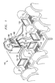
- FIGURE 1 illustrates an embodiment of a portable network system 110 according to the current invention.
- Portable network system 110 may include a deployable network server 120 providing resources to a plurality of computing devices 130 through network connections 140.
- Deployable network server 120 may be accessed by connections 140 through apertures 180.
- Computing devices 130 may include any type of computing device that may utilize resources provided by a network server and include portable and fixed desktop computers.
- deployable network server 120 may be easily transported from one location to the next to provide shared resources to a plurality of computing devices 130 on a temporary basis in a cost efficient manner.
- deployable network server 120 includes all the necessary components to provide network resources to computing devices 130 in one integral device that may be transported by one person. Thus, only one piece of equipment may be required to be transported to provide shared resources to a plurality of computing devices.
- Network connections 140 may be any type of connection operable to connect a network server to a computing device; however, examples of preferred connections 140 include ethernet connections and token ring connections.
- Portable network system 110 allows computing devices 130 to share common resources and efficiently exchange information.
- Portable network system 110 may be particularly useful for providing resources to a small number of computing devices 130 because, as discussed in greater detail below, it may be easily assembled, transported, and selectively configured.
- deployable network server 120 may include a power port 294, shown in FIGURE 2, for providing electrical power to computing devices 130 through connections 150.
- Connections 150 may be electrical power cords or other suitable devices for providing power from power port 294 to computing devices 130.
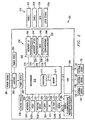
- Deployable network server 120 includes a portable network motherboard 210.
- Portable network motherboard 210 includes a processor 212 and memory 214 associated with the processor 212 for executing resources stored in network server 120.
- Connection 213 allows communication between processor 212 and memory 214; however, processor 212 and memory 214 may be formed as one integral electronic device or chip.
- Portable network motherboard 210 may be operable to execute a variety of types of network software. Examples of such network software include, but are not limited to, Novell, Unix, OS2, and WINDOWS NT®.
- Portable network motherboard 210 preferably has a size and shape that enables it to be assembled with other necessary components of a network server that is operable to provide shared resources to a plurality of computing devices such that the resulting network server may be easily transported by one person.
- portable network server motherboard 210 may be connected with the other components of deployable network server 120 and formed in a carrying case having approximate dimensions of 46 x 20 x 30 cm (18" ⁇ 8" ⁇ 12"); however, other suitable configurations and dimensions for deployable network server 120 that allow it to be easily transported by one person may be used.
- deployable network server 120 includes removable storage devices 220.
- Removable storage devices 220 store resources, such as computer software, which may be shared by computing devices 130.
- Removable storage devices 220 are accessed by portable network motherboard 210 through portable storage device receivers 230.
- Portable storage device receivers 230 provide a temporary connection between removable storage devices 220 and portable network motherboard 210 through storage device receiver connections 216, enabling deployable network server 120 to selectively possess a desired set of resources for shared use by computing devices 130.
- Storage device receiver connections 216 may be small computer system interface (SCSI) connections or other suitable connections for coupling a motherboard to a storage device.
- SCSI small computer system interface
- Portable storage device receivers 230 are preferably formed with a size and shape that enable them to be assembled with other necessary components of a network server that is operable to provide shared resources to a plurality of computing devices such that the resulting network server may be easily transported by one person.
- Removable storage devices 220 may be hot-swappable storage devices.
- a hot-swappable storage device is a storage device that may be interchanged with another hot-swappable storage device while an associated network server is operating. During the interchange, data on hot-swappable storage devices are protected from corruption that may occur due to disconnecting hot-swappable storage devices from associated storage device receivers while an associated network server is operating.
- removable storage devices 220 include a plurality of hot-swappable disk drives 242, 244, 246, and 248.
- storage device receivers 230 include a plurality of hot-swappable drive bays 262, 264, 266, and 268 for receiving the hot-swappable disk drives and for providing a connection between the hot-swappable disk drives and the portable network motherboard 210.
- four removable storage devices 220 and four portable storage device receivers 230 are illustrated in FIGURE 2, other suitable numbers of removable storage devices 220 and storage device receivers may be used.
- six hot-swappable disk drives and associated receivers are utilized.
- Removable storage devices 220 may be selectively engaged with storage device receivers 230 to selectively configure deployable network server 120 with a desired set of resources.
- software stored on removable storage devices 220 may be grouped according to function with a different function served by each removable storage device.
- a first hot-swappable storage disk 242 may store network software such as MICROSOFT NT®
- a second hot-swappable storage disk 244 may store application software such as MICROSOFT OFFICE®
- a third hot-swappable storage disk 246 may store data generated by execution of software stored on one of the other removable storage devices 220
- a fourth hot-swappable storage disk 248 may store communications software such as MICROSOFT MAIL® and additionally store software supporting ethernet connections between computing devices 130 and deployable network server 120.
- hot-swappable disks 242, 244, 246, and 248 may be replaced with a set 270 of hot-swappable disk drives, which includes for example, hot-swappable disks 252, 254, 256, and 258.
- Hot-swappable disk 252 may store, for example, Novell network software
- hot-swappable disk 254 may store, for example, Correll application software
- hot-swappable disk 256 may store data, although it may have a different capacity than hot-swappable disk 246
- hot-swappable disk 258 may store LOTUS CC:MAIL® and additionally support token ring connections between computing devices 130 and deployable network server 120.
- hot-swappable disk 242 which stores network software, may be configured with information describing the contents of the other installed hot-swappable disks 254, 256, and 258.
- set 270 of removable storage devices 220 may be formed having information describing the intended location of resources stored in the set 270 before coupling with portable storage device receivers 230, allowing use of resources stored in storage devices 220 upon coupling with storage device receivers without subsequent configuration.
- deployable network server 120 may be easily configured based on the intended requirements for deployable network server 120. Thus, if computing devices 130 require a particular application or communications capability, such can be provided by the selection of the appropriate combinations of removable storage devices 220. Additionally, the formation of a set 270 of removable storage devices 220 before coupling with portable storage device receivers 230 facilitates configuration of deployable network server 120 at remote locations. Thus, set 270 may be configured at one location by a trained systems analyst and transported to a second location for insertion into portable storage device receivers 230 by one of the users of portable network system 110. The ability to configure deployable network server 120 at one location and use it at another location allows for debugging to be performed well in advance of the time the network server 120 is required.
- Computing devices 130 may access resources stored in hot-swappable drives 210 and stored within the network motherboard memory through portable hub 226.
- Portable hub 226 has a size and shape that enables it to be assembled with other necessary components of a network server that is operable to provide shared resources to a plurality of computing devices such that the resulting network server may be easily transported by one person.
- Portable hub 226 may support any suitable number of connections between computing devices 130 and motherboard 210; however, in one embodiment portable hub 226 provides eight connections, enabling up to eight computing devices 130 to be connected to motherboard 210.
- Computing devices 130 may be connected to portable hub 226 through a variety of types of connections 140.
- connections 140 are RJ-45 connections; however, any connection operable to provide communication between computing devices 130 and portable hub 226 may be used, including for example, ethernet and token ring connections.
- the number of computing devices 130 is small enough that a network card (not explicitly shown) is not used to facilitate communication between computing devices 130 and motherboard 210 via portable hub 226.
- Portable hub 226 may function to allocate priorities to conflicting requests for the deployable network server 120 by computing devices 130.
- Connection 211 allows communication of portable hub 226 with motherboard 210 and may be a direct electrical connection.
- Computing devices 130 may be powered by power ports 294 (connection not explicitly shown in FIGURE 2), which may be an electrical power strip formed as part of deployable network server 120.
- Power ports 294 receive power from a power source 284, which may be a common electrical outlet, through junction 292. Also receiving power from power source 284 through junction 292 is a power supply 282.
- Power supply 282 provides power to portable motherboard 210.
- Junction 292 may be a surge protector and also provide power status to the portable motherboard 210 or to a visual indicator (not explicitly shown).
- a cooling device 258, such as a cooling fan, may also be powered by power port 282 to remove heat generated by the motherboard 210.
- cooling device 258 may be situated to optimize cooling of motherboard 250 because of the increased heat due to compact nature of network server 110.
- Deployable network server 120 may also include a plurality of input/output devices connected to the portable network motherboard 210 for communicating with the deployable network server 120. These input/output devices may include a keyboard 228, a video display1226, a pointing device 1230, and a floppy disk drive 224. These devices may be connected to portable network motherboard through direct electrical connections 229, 227, 231, and 225, respectively; however, other suitable connections may be used. In addition deployable network server 120 may also include an input/output port 1248 for connecting portable network motherboard 210 to additional external devices, such as a printer (not explicitly shown) .
- additional external devices such as a printer (not explicitly shown) .
- Input/output port 248 may be a standard serial/parallel card and may be connected to network server motherboard 210 through a direct electrical connection 249 or other suitable connection. Furthermore, a modem 1246 may be connected to the portable network motherboard 210 through connection 245 for providing a means of communication between deployable network server 120 and remote computers or networks (not explicitly shown). Connection 245 may be a direct electrical connection or other suitable connection for coupling a modem to a motherboard.
- network server 120 is operable to possess a constant electronic address, such as an internet address, regardless of its physical location through, for example, the use of a portable telecommunications transmitter/receiver 286 connected to modem 246 through electrical connection 287.
- a portable communications transmitter/receiver 286 is a cellular phone.
- computers that are not part of portable network server 110 may communicate with deployable network server 120 regardless of its physical location.
- Deployable network server 120 may also include a compact disc drive 222, which may be connected to motherboard 210 through SCSI connection 223 or other suitable connection. Any power required by the above-described input/output devices and the storage device receives 230 may be received directly from portable motherboard 210, from power supply 282, or through other suitable techniques.
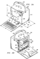
- FIGURES 3A and 3B illustrate one physical implementation of the deployable network server 120 illustrated in FIGURE 1, showing additional details of the deployable network server 120.
- deployable network server 120 includes portable carrying device 200 surrounding motherboard 210, hub 220, and portable storage device receivers 230 for facilitating transportation to desired locations.
- portable carrying device 200 is a flight bag; however, carrying device 200 may include any type of carrying device that may be carried by a single person. It may be particularly advantageous for transporting deployable network server 120 for portable carrying device 200 to conform to size standards for carry-on luggage required by major airlines.
- Carrying device 200 may include a fold-down front 310 and fold-down back 312 for providing easy access to various components of deployable network server 120.
- Fold-down back 312 may include apertures 180 for providing access to hub 236, removable storage device receivers 230, power ports 294, and input/output port 248 while fold-down back 312 is in an upright position.
- Compartment 330 encases network motherboard 210 and fan 258 to minimize dust and static.
- Carrying device 200 may also include a handle 232 and shoulder strap 234 to further facilitate transportation and may be formed with ruggedized portions 238 to protect deployable network server 120 during transportation.
- video display 226, compact disk drive 222, and floppy disk drive 224 are illustrated as accessible through front flap 310 and formed in interior front face 320.
- keyboard 228 may connect to portable network motherboard 210 (FIGURE 3B) through keyboard input port 229 formed in an interior front face 320 of deployable network server 120.
- Pointing device 230 may connect to portable network motherboard 210 through pointing device input port 231 formed in interior front face 320 of deployable network server 120.
- Keyboard 228 may optionally be formed integral with front flap 310.
- portable network motherboard 210 is illustrated in a horizontal position overlying power ports 294; however, any suitable orientation that allows portable network motherboard 210 to fit within portable carrying case 200 may be used in this embodiment.
- Cooling device 258 may be oriented to provide fluid flow directly over portable network motherboard 210 to enhance heat transfer from deployable network server 120 to the surrounding environment.
- Input/output port 248, modem 246, and portable telecommunications transmitter/receiver 286 may be oriented vertically in this embodiment as illustrated in FIGURE 3B; however, any suitable orientation that allows these components to fit within portable carrying case 200 or attached to portable carrying case 200 may be used in this embodiment.
- Portable hub 226 may be positioned, as shown, overlying portable storage device receivers 230.
- Portable storage device receivers 230 are illustrated in FIGURE 3B as being positioned for receiving removable storage devices 220 through apertures 180 of back flap 312 of portable carrying device 200; however, other suitable orientations for hub 226 and storage device receivers 230 that allow portable hub 226 and storage device receivers to fit within portable carrying case 200 may be utilized in this embodiment.
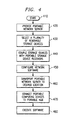
- FIGURE 4 is a flow chart illustrating the operation of deployable network server 120 and a method for providing shared resources to a group of users.
- the method begins at step 410.
- a deployable network server such as deployable network server 120
- a plurality of removable storage devices 220 having desired resources is selected based on the requirements of a particular application. For example, a proposal team may require a particular type of word processing software that functions with a particular type of network software and, in addition, a particular type of electronic mail package.
- removable storage devices 220 are then coupled with portable storage device receivers 230 on deployable network server 120.
- the network software stored on one of the selected removable storage devices 220 may then be configured based on the contents and location of software stored on other removable storage devices 220; however, such configuration, if needed, may alternatively be performed before coupling removable storage devices 220 with storage device receivers 230.
- One method for configuring network software before coupling removable storage devices 220 with storage device receivers 230 is to configure the network software while storage devices 220 are inserted into a second network server having storage device receives capable of receiving storage devices 220. In this manner, a set of removable storage devices, such as set 270, may be pre-configured so they may be accessed upon coupling with storage device receivers 230 without additional configuration. This procedure facilitates formation of a portable network such as network 110 without requiring a trained systems analyst to travel to the location of the network.
- network server is then transported to the desired location of a network.
- Deployable network server 120 may then be plugged into a power source 284 and front flap 310 may be lowered to provide access to keyboard 228, video display 226, pointing device 230, floppy disk drive 224, and compact disk drive 222 to facilitate use of deployable network server 120.
- step 460 could occur before or after coupling removable storage devices 220 with storage device receivers 230.
- a plurality of portable computing devices 130 may be connected to deployable network server 120 through connections 140 and hub 226.
- the plurality of portable computing devices 130 may also be powered by power ports 294.
- Resources stored on removable storage devices 220 may then be accessed and utilized by computing devices 130. In this manner, a plurality of computing devices may share a common set of resources and efficiently exchange information. In addition, these resources may be selectively and easily configured through organizing software by category on removable storage devices 220.
Landscapes
- Engineering & Computer Science (AREA)
- Computer Hardware Design (AREA)
- Theoretical Computer Science (AREA)
- General Engineering & Computer Science (AREA)
- Physics & Mathematics (AREA)
- General Physics & Mathematics (AREA)
- Human Computer Interaction (AREA)
- Computer Networks & Wireless Communication (AREA)
- Signal Processing (AREA)
- Computer And Data Communications (AREA)
- Information Transfer Between Computers (AREA)
- Information Retrieval, Db Structures And Fs Structures Therefor (AREA)
- Stored Programmes (AREA)
Abstract
Claims (15)
- Appareil portable (120) pour attribuer sélectivement des ressources à une pluralité de dispositifs informatiques externes (130), l'appareil étant caractérisé en ce qu'il comprend :une carte mère de serveur de réseau portable (120);une pluralité de dispositifs mémoires amovibles (220), chaque dispositif mémoire stockant une catégorie différente de ressources;une pluralité de récepteurs de dispositifs mémoires amovibles portables (230) connectant la pluralité de dispositifs mémoires amovibles à la carte mère (210) du serveur de réseau portable; etun concentrateur portable (226) qui est à même de connecter la carte mère (210) du serveur de réseau portable à ladite pluralité de dispositifs informatiques externes (130).
- Appareil selon la revendication 1, dans lequel la pluralité de dispositifs mémoires amovibles (220) ou (270) comprend une pluralité d'unités de disques remplaçables à chaud (242, 244, 246, 248 ou 252, 254, 256, 258).
- Appareil selon la revendication 1, comprenant en outre un boítier de transport portable (200) entourant la carte mère (210) du serveur de réseau portable, la pluralité de dispositifs mémoires amovibles (220), la pluralité de récepteurs de dispositifs mémoires amovibles portables (262, 264, 266, 268) et le concentrateur portable (226).
- Appareil selon la revendication 3, comprenant en outre un dispositif de refroidissement (258) situé à l'intérieur du boítier de transport portable (200) pour refroidir la carte mère (210) du serveur de réseau portable.
- Appareil selon la revendication 1, dans lequel la pluralité de dispositifs mémoires amovibles (220) comprend un premier dispositif mémoire remplaçable à chaud (242 ou 252) stockant tout le logiciel de réseau accessible par la carte mère (210) du réseau portable et un second dispositif mémoire remplaçable à chaud (244 ou 254) stockant tout le logiciel d'application accessible par la carte mère (210) du réseau portable.
- Appareil selon la revendication 2, dans lequel la pluralité de dispositifs mémoires amovibles (220 ou 270) comprend :une première unité de disques remplaçable à chaud (242 ou 252) stockant un logiciel constitué essentiellement d'un logiciel de réseau;une deuxième unité de disques remplaçable à chaud (244 ou 254) stockant le logiciel constitué essentiellement d'un logiciel d'application;une troisième unité de disques remplaçable à chaud (246 ou 256) stockant des données générées par l'exécution du logiciel d'application stocké sur la deuxième unité de disques remplaçable à chaud (244 ou 254); etune quatrième unité de disques remplaçable à chaud (248 ou 258) stockant le logiciel constitué essentiellement d'un logiciel de communications.
- Appareil selon la revendication 1, comprenant par ailleurs un modem (1246) connecté à la carte mère portable (210) et un émetteur/récepteur de télécommunications portable (286) connecté au modem (1246).
- Procédé pour attribuer des ressources partagées issues d'un appareil portable (120) à des dispositifs informatiques externes (130), le procédé étant caractérisé en ce qu'il comprend les étapes consistant à :mettre en oeuvre (420) un serveur de réseau portable (120) ayant une pluralité de récepteurs de dispositifs mémoires amovibles portables (230) et un concentrateur portable (126) connecté à une carte mère portable (210) du serveur de réseau;mettre en oeuvre (430) une première pluralité de dispositifs mémoires amovibles (220), les dispositifs mémoires amovibles choisies (220 ou 270) comprenant un premier dispositif mémoire amovible (242 ou 252) stockant tout le logiciel de réseau accessible par la carte mère portable (210) du serveur de réseau et un deuxième dispositif mémoire amovible (244 ou 254) stockant tout le logiciel d'application accessible par la carte mère portable (210) du serveur de réseau; etconnecter (440) la pluralité des dispositifs mémoires amovibles (220; 242, 244, 246, 248 ou 270; 252, 254, 256, 258) de manière une à une avec la pluralité de récepteurs de dispositifs mémoires amovibles portables (262, 264, 266, 268).
- Procédé selon la revendication 8, comprenant par ailleurs la configuration du premier dispositif mémoire (242 ou 252) sur la base de la première pluralité choisie de dispositifs mémoires amovibles (220 ou 270).
- Procédé selon la revendication 8, comprenant par ailleurs la configuration (450) de la première mémoire (242 ou 252) sur la base de la première pluralité choisie de dispositifs mémoires amovibles (220 ou 470) avant de connecter la première mémoire (242 ou 252) à son récepteur de dispositif mémoire amovible portable associé (262).
- Procédé selon la revendication 8, dans lequel la première pluralité de dispositifs mémoires amovibles (220 ou 270) comprend un troisième mémoire (246 ou 256) pour stocker des données générées par l'exécution du logiciel sur la deuxième mémoire (244 ou 254).
- Procédé selon la revendication 8, comprenant par ailleurs les étapes consistant à :transporter (460) le serveur de réseau portable (120) d'un premier emplacement à un deuxième emplacement dans un boítier de transport portable (200);connecter (470) une pluralité de dispositifs informatiques externes portables (130) au concentrateur portable (226); etexécuter (480) une partie du logiciel d'application en réponse aux informations communiquées par l'un des dispositifs informatiques externes (130) à la carte mère portable (210) du réseau.
- Procédé selon la revendication 8, comprenant par ailleurs les étapes consistant à :connecter le serveur de réseau portable (120) à un émetteur/récepteur de télécommunications (286);transporter le serveur de réseau portable (120) et l'émetteur/récepteur de télécommunications (286) à un premier emplacement;connecter une pluralité de dispositifs informatiques (130) au concentrateur portable (226); etaccéder à un réseau d'ordinateurs via un dispositif informatique externe (130), le concentrateur portable (226) et l'émetteur/récepteur de télécommunications (286).
- Procédé selon la revendication 13, dans lequel l'étape d'exécution d'une partie du logiciel d'application se fait tandis le concentrateur portable (262) est situé dans le boítier de transport portable (200).
- Procédé selon la revendication 8, comprenant par ailleurs la sélection d'une deuxième pluralité de dispositifs mémoires amovibles (270 ou 220) sur la base des besoins d'une deuxième pluralité de dispositifs informatiques externes, la deuxième pluralité de dispositifs mémoires amovibles (270 ou 220) étant différente de la première pluralité de dispositifs mémoires amovibles (220 ou 270).
Applications Claiming Priority (3)
| Application Number | Priority Date | Filing Date | Title |
|---|---|---|---|
| US800673 | 1991-11-27 | ||
| US08/800,673 US6003068A (en) | 1997-02-14 | 1997-02-14 | Method and apparatus for portably providing shared removable resources to a plurality of computing devices |
| PCT/US1998/002270 WO1998036345A1 (fr) | 1997-02-14 | 1998-02-13 | Procede et appareil d'attribution de ressources partagees a une pluralite de dispositifs informatiques |
Publications (2)
| Publication Number | Publication Date |
|---|---|
| EP0960367A1 EP0960367A1 (fr) | 1999-12-01 |
| EP0960367B1 true EP0960367B1 (fr) | 2004-06-16 |
Family
ID=25179048
Family Applications (1)
| Application Number | Title | Priority Date | Filing Date |
|---|---|---|---|
| EP98904960A Expired - Lifetime EP0960367B1 (fr) | 1997-02-14 | 1998-02-13 | Procede et appareil d'attribution de ressources partagees a une pluralite de dispositifs informatiques |
Country Status (5)
| Country | Link |
|---|---|
| US (1) | US6003068A (fr) |
| EP (1) | EP0960367B1 (fr) |
| CA (1) | CA2280958C (fr) |
| DE (1) | DE69824553T2 (fr) |
| WO (1) | WO1998036345A1 (fr) |
Families Citing this family (34)
| Publication number | Priority date | Publication date | Assignee | Title |
|---|---|---|---|---|
| US5694546A (en) | 1994-05-31 | 1997-12-02 | Reisman; Richard R. | System for automatic unattended electronic information transport between a server and a client by a vendor provided transport software with a manifest list |
| JP3731980B2 (ja) * | 1997-08-20 | 2006-01-05 | 富士通株式会社 | コンピュータネットワークシステム及び携帯型コンピュータ |
| US6295556B1 (en) * | 1997-11-18 | 2001-09-25 | Microsoft Corporation | Method and system for configuring computers to connect to networks using network connection objects |
| FR2788355A1 (fr) * | 1999-01-12 | 2000-07-13 | Team Concepts Europ | Jeu educatif electronique |
| US6850512B1 (en) * | 1999-08-26 | 2005-02-01 | Ipr Licensing, Inc. | Two tier hi-speed wireless communication link |
| JP4119063B2 (ja) * | 1999-11-05 | 2008-07-16 | 株式会社東芝 | メッセージ処理装置、メッセージ処理システム及びメッセージ処理方法 |
| US7072939B1 (en) * | 2000-01-27 | 2006-07-04 | International Business Machines Corporation | Instant selective multiple soft document sharing between multiple heterogeneous computing devices |
| US7149511B1 (en) * | 2000-08-31 | 2006-12-12 | Rosetta-Wireless Corporation | Wireless intelligent personal server |
| GB2371711B (en) * | 2000-11-27 | 2004-07-07 | Nokia Mobile Phones Ltd | A Server |
| US20020152285A1 (en) * | 2001-01-31 | 2002-10-17 | Wheeler Troy M. | Remote office system for retail and other sales and services |
| US20020138615A1 (en) * | 2001-03-21 | 2002-09-26 | Schmeling Garth F. | System and method for device management through world wide web confederacy |
| US6738851B2 (en) * | 2001-05-23 | 2004-05-18 | Highpoint Technologies, Inc. | Hot swap safeguard circuit of ultra DMA hard disk |
| US20030039261A1 (en) * | 2001-08-21 | 2003-02-27 | Purpura William J. | Portable Mini-hub for local area networks |
| US20030157959A1 (en) * | 2002-01-11 | 2003-08-21 | Jakke Makela | Method, system, apparatus and computer program product for portable networking of multi-user applications |
| US7006481B2 (en) * | 2002-10-10 | 2006-02-28 | Interdigital Technology Corporation | System and method for integrating WLAN and 3G |
| US7742821B1 (en) * | 2003-06-11 | 2010-06-22 | Boston Scientific Neutomodulation Corporation | Remote control for implantable medical device |
| EP1482720A1 (fr) * | 2003-05-28 | 2004-12-01 | Ricoh Company, Ltd. | Dispositif de traitement d'image et produit d'ordinateur |
| US7370157B2 (en) * | 2005-05-24 | 2008-05-06 | Hewlett-Packard Development Company, L.P. | Systems and methods of sharing removable media storage devices in multi-partitioned systems |
| US7573713B2 (en) | 2005-09-13 | 2009-08-11 | Pacific Star Communications | High velocity air cooling for electronic equipment |
| US7535861B2 (en) | 2005-10-07 | 2009-05-19 | Pacific Star Communications Inc. | Self-contained portable broadband communication system |
| US7817589B2 (en) | 2006-02-21 | 2010-10-19 | Pacific Star Communications, Inc. | Self-contained portable broadband communications system |
| GB2437353A (en) * | 2006-03-27 | 2007-10-24 | Charles Daniel | Distributing data from a pc server through ethernet or wireless connections to portable network devices through low voltage conductors |
| TWM309192U (en) * | 2006-08-31 | 2007-04-01 | Ritek Corp | Portable disk |
| KR20090081616A (ko) * | 2008-01-24 | 2009-07-29 | 삼성전자주식회사 | 공유 소프트웨어의 관리 방법 및 디바이스 |
| US20090265412A1 (en) * | 2008-03-03 | 2009-10-22 | Eric Hainzer | Plural Computer System |
| US8120913B2 (en) * | 2009-06-29 | 2012-02-21 | Rosemount Aerospace Inc. | Methods and devices for forced air cooling of electronic flight bags |
| GB0921402D0 (en) | 2009-12-07 | 2010-01-20 | Regenersis Plc | A testing apparatus and method |
| US10061620B2 (en) * | 2012-07-02 | 2018-08-28 | Paypal, Inc. | System and method for clustering of mobile devices and applications |
| DK177618B1 (en) * | 2013-03-13 | 2013-12-09 | Aporta Digital Aps | Robust mobile media server and method for providing media to passengers in a public transport vehicle |
| DE102015224950A1 (de) * | 2015-12-11 | 2017-06-14 | Airbus Operations Gmbh | Technik zum Aktualisieren von Software an Bord eines Flugzeugs |
| FR3075415B1 (fr) * | 2017-12-19 | 2019-11-08 | Electricite De France | Plateforme virtuelle mobile de mise en reseau |
| US10462912B1 (en) * | 2017-12-21 | 2019-10-29 | Klas Technologies Limited | Tactical data center system |
| US11079820B2 (en) | 2019-01-15 | 2021-08-03 | Microsoft Technology Licensing, Llc | Method and apparatus for improving removable storage performance |
| US11520311B2 (en) | 2019-07-25 | 2022-12-06 | Microsoft Technology Licensing, Llc | High performance removable storage devices |
Family Cites Families (10)
| Publication number | Priority date | Publication date | Assignee | Title |
|---|---|---|---|---|
| DE69024753T2 (de) * | 1989-10-31 | 1996-05-30 | Hewlett Packard Co | Tragbarer, Ressourcen teilender Datei-Server, der gemeinsame Routines benutzt |
| US5301346A (en) * | 1991-06-21 | 1994-04-05 | Cad Forms Technology Inc. | Method and apparatus for transferring data between a host device and plurality of portable computers |
| US5305183A (en) * | 1991-07-09 | 1994-04-19 | Edison Welding Institute | Portable personal computer with passive backplane having a doublesided staggered connector array |
| ATE173877T1 (de) * | 1992-06-29 | 1998-12-15 | Elonex Technologies Inc | Modular tragbarer rechner |
| US5692128A (en) * | 1993-06-23 | 1997-11-25 | Microtest, Inc. | Computer network with reliable and efficient removable media services |
| US5486982A (en) * | 1994-06-10 | 1996-01-23 | Hsu; Winston | Modular electronic packaging for computer servers |
| JPH0855156A (ja) * | 1994-07-12 | 1996-02-27 | Internatl Business Mach Corp <Ibm> | 工程安全管理のためのコンピュータ・システムおよび方法 |
| US5671407A (en) * | 1994-12-07 | 1997-09-23 | Xerox Corporation | Application-specific conflict detection for weakly consistent replicated databases |
| US5802305A (en) * | 1996-05-17 | 1998-09-01 | Microsoft Corporation | System for remotely waking a sleeping computer in power down state by comparing incoming packet to the list of packets storing on network interface card |
| US5790790A (en) * | 1996-10-24 | 1998-08-04 | Tumbleweed Software Corporation | Electronic document delivery system in which notification of said electronic document is sent to a recipient thereof |
-
1997
- 1997-02-14 US US08/800,673 patent/US6003068A/en not_active Expired - Fee Related
-
1998
- 1998-02-13 CA CA002280958A patent/CA2280958C/fr not_active Expired - Fee Related
- 1998-02-13 EP EP98904960A patent/EP0960367B1/fr not_active Expired - Lifetime
- 1998-02-13 DE DE69824553T patent/DE69824553T2/de not_active Expired - Fee Related
- 1998-02-13 WO PCT/US1998/002270 patent/WO1998036345A1/fr not_active Ceased
Also Published As
| Publication number | Publication date |
|---|---|
| CA2280958C (fr) | 2006-05-16 |
| DE69824553D1 (de) | 2004-07-22 |
| DE69824553T2 (de) | 2005-08-18 |
| US6003068A (en) | 1999-12-14 |
| EP0960367A1 (fr) | 1999-12-01 |
| CA2280958A1 (fr) | 1998-08-20 |
| WO1998036345A1 (fr) | 1998-08-20 |
Similar Documents
| Publication | Publication Date | Title |
|---|---|---|
| EP0960367B1 (fr) | Procede et appareil d'attribution de ressources partagees a une pluralite de dispositifs informatiques | |
| US5436857A (en) | Personal computer module system and method of using | |
| US7937705B1 (en) | Dynamic job processing based on estimated completion time and specified tolerance time | |
| US20050262269A1 (en) | System and method for information handling system PCI express advanced switching | |
| US20060092928A1 (en) | System and method for providing a shareable input/output device in a PCI express environment | |
| EP0677943A3 (fr) | Système de communication pour échanger des données entre ordinateurs dans un réseau | |
| US20050163123A1 (en) | Method and apparatus for implementing a MAC address pool for assignment to a virtual interface aggregate | |
| US8544065B2 (en) | Dataspace protection utilizing virtual private networks on a multi-node computer system | |
| WO1994022102A1 (fr) | Chassis pour systeme informatique multiple | |
| EP0703522A2 (fr) | Système multi-ordinateur | |
| CN113805951B (zh) | 一种基于arinc653标准的服务分区设备共享的端口映射方法 | |
| US7266820B2 (en) | Trunked customized connectivity process for installing software onto an information handling system | |
| US20100034117A1 (en) | Parallel vlan and non-vlan device configuration | |
| US5666491A (en) | Portable network adapter for portable computer | |
| US20040215842A1 (en) | System and method for aggregating shelf IDs in a fibre channel storage loop | |
| CN1578267B (zh) | 处理分组以在主机系统的网络上传送的方法、系统及装置 | |
| US20060095335A1 (en) | Inventory management of resources | |
| US6205470B1 (en) | System uses network mainframe and servers for processing of checks to minimize system usage interruptions | |
| JP2000284853A (ja) | 持ち運び可能なネットワーク型コンピューティング装置及びその使用方法 | |
| Fortier | CRC Handbook of Local Area Network Software: Concepts and Technology | |
| US20040047355A1 (en) | Method of providing low cost network storage | |
| IE84641B1 (en) | Information handling system with PCI express advanced switching | |
| Yet | THIN COMPUTING | |
| Ullmann | Deutsches Forschungsnetz (DFN)-Data Communication Services for the Scientific Community in Germany | |
| Bevan | Corporate networking and the PC |
Legal Events
| Date | Code | Title | Description |
|---|---|---|---|
| PUAI | Public reference made under article 153(3) epc to a published international application that has entered the european phase |
Free format text: ORIGINAL CODE: 0009012 |
|
| 17P | Request for examination filed |
Effective date: 19990907 |
|
| AK | Designated contracting states |
Kind code of ref document: A1 Designated state(s): BE CH DE DK FI FR GB GR IT LI LU NL SE |
|
| 17Q | First examination report despatched |
Effective date: 20020611 |
|
| GRAP | Despatch of communication of intention to grant a patent |
Free format text: ORIGINAL CODE: EPIDOSNIGR1 |
|
| GRAS | Grant fee paid |
Free format text: ORIGINAL CODE: EPIDOSNIGR3 |
|
| GRAA | (expected) grant |
Free format text: ORIGINAL CODE: 0009210 |
|
| AK | Designated contracting states |
Kind code of ref document: B1 Designated state(s): BE CH DE DK FI FR GB GR IT LI LU NL SE |
|
| PG25 | Lapsed in a contracting state [announced via postgrant information from national office to epo] |
Ref country code: NL Free format text: LAPSE BECAUSE OF FAILURE TO SUBMIT A TRANSLATION OF THE DESCRIPTION OR TO PAY THE FEE WITHIN THE PRESCRIBED TIME-LIMIT Effective date: 20040616 Ref country code: LI Free format text: LAPSE BECAUSE OF FAILURE TO SUBMIT A TRANSLATION OF THE DESCRIPTION OR TO PAY THE FEE WITHIN THE PRESCRIBED TIME-LIMIT Effective date: 20040616 Ref country code: CH Free format text: LAPSE BECAUSE OF FAILURE TO SUBMIT A TRANSLATION OF THE DESCRIPTION OR TO PAY THE FEE WITHIN THE PRESCRIBED TIME-LIMIT Effective date: 20040616 Ref country code: BE Free format text: LAPSE BECAUSE OF FAILURE TO SUBMIT A TRANSLATION OF THE DESCRIPTION OR TO PAY THE FEE WITHIN THE PRESCRIBED TIME-LIMIT Effective date: 20040616 |
|
| REG | Reference to a national code |
Ref country code: GB Ref legal event code: FG4D |
|
| REG | Reference to a national code |
Ref country code: CH Ref legal event code: EP |
|
| REF | Corresponds to: |
Ref document number: 69824553 Country of ref document: DE Date of ref document: 20040722 Kind code of ref document: P |
|
| PG25 | Lapsed in a contracting state [announced via postgrant information from national office to epo] |
Ref country code: SE Free format text: LAPSE BECAUSE OF FAILURE TO SUBMIT A TRANSLATION OF THE DESCRIPTION OR TO PAY THE FEE WITHIN THE PRESCRIBED TIME-LIMIT Effective date: 20040916 Ref country code: GR Free format text: LAPSE BECAUSE OF FAILURE TO SUBMIT A TRANSLATION OF THE DESCRIPTION OR TO PAY THE FEE WITHIN THE PRESCRIBED TIME-LIMIT Effective date: 20040916 Ref country code: DK Free format text: LAPSE BECAUSE OF FAILURE TO SUBMIT A TRANSLATION OF THE DESCRIPTION OR TO PAY THE FEE WITHIN THE PRESCRIBED TIME-LIMIT Effective date: 20040916 |
|
| NLV1 | Nl: lapsed or annulled due to failure to fulfill the requirements of art. 29p and 29m of the patents act | ||
| REG | Reference to a national code |
Ref country code: CH Ref legal event code: PL |
|
| ET | Fr: translation filed | ||
| PG25 | Lapsed in a contracting state [announced via postgrant information from national office to epo] |
Ref country code: LU Free format text: LAPSE BECAUSE OF NON-PAYMENT OF DUE FEES Effective date: 20050213 |
|
| PLBE | No opposition filed within time limit |
Free format text: ORIGINAL CODE: 0009261 |
|
| STAA | Information on the status of an ep patent application or granted ep patent |
Free format text: STATUS: NO OPPOSITION FILED WITHIN TIME LIMIT |
|
| 26N | No opposition filed |
Effective date: 20050317 |
|
| PGFP | Annual fee paid to national office [announced via postgrant information from national office to epo] |
Ref country code: DE Payment date: 20090331 Year of fee payment: 12 |
|
| REG | Reference to a national code |
Ref country code: FR Ref legal event code: TP Ref country code: FR Ref legal event code: CD |
|
| REG | Reference to a national code |
Ref country code: GB Ref legal event code: 732E Free format text: REGISTERED BETWEEN 20100408 AND 20100414 |
|
| PGFP | Annual fee paid to national office [announced via postgrant information from national office to epo] |
Ref country code: IT Payment date: 20100224 Year of fee payment: 13 Ref country code: FR Payment date: 20100303 Year of fee payment: 13 Ref country code: FI Payment date: 20100301 Year of fee payment: 13 |
|
| PGFP | Annual fee paid to national office [announced via postgrant information from national office to epo] |
Ref country code: GB Payment date: 20100224 Year of fee payment: 13 |
|
| PG25 | Lapsed in a contracting state [announced via postgrant information from national office to epo] |
Ref country code: DE Free format text: LAPSE BECAUSE OF NON-PAYMENT OF DUE FEES Effective date: 20100901 |
|
| GBPC | Gb: european patent ceased through non-payment of renewal fee |
Effective date: 20110213 |
|
| REG | Reference to a national code |
Ref country code: FR Ref legal event code: ST Effective date: 20111102 |
|
| PG25 | Lapsed in a contracting state [announced via postgrant information from national office to epo] |
Ref country code: FI Free format text: LAPSE BECAUSE OF NON-PAYMENT OF DUE FEES Effective date: 20110213 |
|
| PG25 | Lapsed in a contracting state [announced via postgrant information from national office to epo] |
Ref country code: IT Free format text: LAPSE BECAUSE OF NON-PAYMENT OF DUE FEES Effective date: 20110213 |
|
| PG25 | Lapsed in a contracting state [announced via postgrant information from national office to epo] |
Ref country code: FR Free format text: LAPSE BECAUSE OF NON-PAYMENT OF DUE FEES Effective date: 20110228 |
|
| PG25 | Lapsed in a contracting state [announced via postgrant information from national office to epo] |
Ref country code: GB Free format text: LAPSE BECAUSE OF NON-PAYMENT OF DUE FEES Effective date: 20110213 |