EP0960432B1 - Hochdruckentladungslampe - Google Patents
Hochdruckentladungslampe Download PDFInfo
- Publication number
- EP0960432B1 EP0960432B1 EP98955870A EP98955870A EP0960432B1 EP 0960432 B1 EP0960432 B1 EP 0960432B1 EP 98955870 A EP98955870 A EP 98955870A EP 98955870 A EP98955870 A EP 98955870A EP 0960432 B1 EP0960432 B1 EP 0960432B1
- Authority
- EP
- European Patent Office
- Prior art keywords
- end part
- outside surface
- lamp
- ceramic
- location
- Prior art date
- Legal status (The legal status is an assumption and is not a legal conclusion. Google has not performed a legal analysis and makes no representation as to the accuracy of the status listed.)
- Expired - Lifetime
Links
- 239000000919 ceramic Substances 0.000 claims description 25
- 239000004020 conductor Substances 0.000 claims description 13
- 238000007789 sealing Methods 0.000 claims description 10
- 238000005245 sintering Methods 0.000 claims description 7
- 229910001507 metal halide Inorganic materials 0.000 claims description 4
- 150000005309 metal halides Chemical class 0.000 claims description 4
- 238000010276 construction Methods 0.000 description 14
- 238000000034 method Methods 0.000 description 4
- PNEYBMLMFCGWSK-UHFFFAOYSA-N Alumina Chemical compound [O-2].[O-2].[O-2].[Al+3].[Al+3] PNEYBMLMFCGWSK-UHFFFAOYSA-N 0.000 description 3
- 239000011195 cermet Substances 0.000 description 3
- 238000001125 extrusion Methods 0.000 description 3
- 230000002349 favourable effect Effects 0.000 description 3
- 150000004820 halides Chemical class 0.000 description 3
- 238000004519 manufacturing process Methods 0.000 description 3
- 239000000463 material Substances 0.000 description 3
- 230000008646 thermal stress Effects 0.000 description 3
- 230000015572 biosynthetic process Effects 0.000 description 2
- 230000008020 evaporation Effects 0.000 description 2
- 238000001704 evaporation Methods 0.000 description 2
- 229910044991 metal oxide Inorganic materials 0.000 description 2
- 150000004706 metal oxides Chemical class 0.000 description 2
- 229910017083 AlN Inorganic materials 0.000 description 1
- PIGFYZPCRLYGLF-UHFFFAOYSA-N Aluminum nitride Chemical compound [Al]#N PIGFYZPCRLYGLF-UHFFFAOYSA-N 0.000 description 1
- 239000004411 aluminium Substances 0.000 description 1
- 229910052782 aluminium Inorganic materials 0.000 description 1
- XAGFODPZIPBFFR-UHFFFAOYSA-N aluminium Chemical compound [Al] XAGFODPZIPBFFR-UHFFFAOYSA-N 0.000 description 1
- 229910010293 ceramic material Inorganic materials 0.000 description 1
- 229910052751 metal Inorganic materials 0.000 description 1
- 239000002184 metal Substances 0.000 description 1
- SIWVEOZUMHYXCS-UHFFFAOYSA-N oxo(oxoyttriooxy)yttrium Chemical compound O=[Y]O[Y]=O SIWVEOZUMHYXCS-UHFFFAOYSA-N 0.000 description 1
- 239000011819 refractory material Substances 0.000 description 1
- 229910052594 sapphire Inorganic materials 0.000 description 1
- 239000010980 sapphire Substances 0.000 description 1
- 230000035882 stress Effects 0.000 description 1
- 238000004804 winding Methods 0.000 description 1
- 229910052727 yttrium Inorganic materials 0.000 description 1
- VWQVUPCCIRVNHF-UHFFFAOYSA-N yttrium atom Chemical compound [Y] VWQVUPCCIRVNHF-UHFFFAOYSA-N 0.000 description 1
Images


Classifications
-
- H—ELECTRICITY
- H01—ELECTRIC ELEMENTS
- H01J—ELECTRIC DISCHARGE TUBES OR DISCHARGE LAMPS
- H01J61/00—Gas-discharge or vapour-discharge lamps
- H01J61/02—Details
- H01J61/36—Seals between parts of vessels; Seals for leading-in conductors; Leading-in conductors
- H01J61/361—Seals between parts of vessel
- H01J61/363—End-disc seals or plug seals
Definitions
- the invention relates to a high-pressure discharge lamp comprising a ceramic discharge vessel which encloses a discharge space which contains an ionizable filling including a metal halide and which accommodates a first and a second electrode, which discharge vessel has a longitudinal axis and is provided with
- a ceramic discharge vessel is to be taken to mean a discharge vessel provided with a wall of a refractory material, such as monocrystalline metal oxide (for example sapphire), gastight sintered polycrystalline metal oxide (for example polycrystalline aluminium oxide; yttrium aluminium granate or yttrium oxide) and polycrystalline gastight sintered non-oxidic material (for example aluminium nitride).
- monocrystalline metal oxide for example sapphire
- gastight sintered polycrystalline metal oxide for example polycrystalline aluminium oxide; yttrium aluminium granate or yttrium oxide
- polycrystalline gastight sintered non-oxidic material for example aluminium nitride
- the sintered connection to the end part extends over a length of at least 2 mm.
- a length of the sintered connection proved to be sufficient to form a strong and gastight fastening, also in the case of large-scale series production.
- the sintered connection between the wall of the end part and the projecting plug extends over a length of at least 2 mm.
- Each sintered connection between two parts forms a sintering seam.
- a discharge vessel constructed in said manner can be very reproducibly produced in series on an industrial scale. It is advantageous that the discharge vessel is composed of a limited number of prefabricated shaped parts which, as a result of their relatively simple shapes, can be manufactured very accurately and subsequently sintered to form the intended ceramic body in a single sintering process.
- the projecting plug is preferably shaped as a cilindrical tube.
- Such a shape is very suitable to be manufactured with high accuracy on an industrial scale in series by way of extrusion.
- the resultant reproducible dimensional accuracy of the discharge vessel is very important for obtaining a good color stability of the lamp during its service life.
- the known lamp has a quantity of sealing ceramic at the location of the sintering seam between the outside surface of the end part and the projecting plug. Said sealing ceramic may be covered with an additional slice of ceramic material.
- a lamp of the type mentioned in the opening paragraph is characterized in accordance with the invention in that at the location of the projecting plug, the outside surface of the end part is positioned so as to be axially remote from the discharge space with respect to the outside surface at the location of the end.
- the lamp in accordance with the invention has the advantage that, by means of an important simplification of the manufacturing process, it has been achieved that not only the risk of leakage of the discharge vessel has been substantially reduced, but even the risk of crack formation in the end part and/or the projecting plug due to thermal stresses. As a result thereof, it has also been achieved that a reduction of the service life of the lamp due to evaporation of sealing ceramic is precluded.
- the end part is monolithic and the outside surface includes an angle A with the longitudinal axis, at the location of the projecting plug, which angle, expressed in degrees, meets the following relation 30 ⁇ A ⁇ 60.
- This form of attachment between the end part and the projecting plug causes internal stresses to be homogeneously distributed over the end part, which has a very favorable influence on the further reduction of the risk of crack formation caused by thermal stresses.
- the outside surface of the end part is shaped like a truncated cone provided with a foot at its base, a very robust lamp-vessel construction having favorable thermal properties is obtained. Said cap may be widened with respect to the base of the cone.
- the end part is composed of at least 2 concentric tubular portions which are interconnected in a gastight manner by sintering.
- This embodiment has the special advantage that all prefabricated ceramic shaped parts of which the discharge vessel is composed can be formed by means of an extrusion process.
- the measure in accordance with the invention can be particularly advantageously applied to a lamp having a rated wattage of more than 150 W.
- the measure can particularly suitably be used in a metal-halide lamp.
- Fig. 1 shows a high-pressure discharge lamp comprising a ceramic discharge vessel 3 having a ceramic wall which encloses a discharge space 11 which contains an ionizable filling. Said discharge space accommodates a first electrode 4 and a second electrode 5 having tips situated at a distance EA from one another.
- the discharge vessel has a longitudinal axis 300.
- the discharge vessel is surrounded by an outer bulb 1 which is provided at one end with a lamp cap 2.
- Electrode 4 is connected via a current conductor 8 to a first electrical contact which forms part of the lamp cap 2.
- Electrode 5 is connected via a current conductor 9 to a second electrical contact which forms part of the lamp cap 2.
- the discharge vessel which is shown in greater detail (not to scale) in Fig. 2, is provided with
- the outside surface of the end part is positioned so as to be axially remote from the discharge space with respect to the outside surface at the location of the end 322a, 322b.
- the end parts 32a, 32b are monolithic. Since, at the location of the outside surface 320a, 320b, the sintered connection S extends parallel to the longitudinal axis 300, the outside surface of the end part 32a, 32b includes an angle A, at the location of the projecting plug 321a, 321b, with the longitudinal axis of 45 degrees and thus satisfies the relation 30 ⁇ A ⁇ 60.
- the outside surface 320a, 320b of the end part 32a, 32b has the shape of a truncated cone which is provided at its base with a foot 325a, 325b.
- the height of the foot corresponds to the length of the gastight connection T between the end 310 of the cylindrical part 31 and the end part 32a, 32b.
- the current feedthrough conductors comprise a substantially halide-resistant part 41, 51, respectively, for example in the form of an Mo-Al 2 O 3 -cermet and a part 40, 50, respectively, which is secured in a gastight manner by means of the sealing ceramic connection 10 to a relevant end plug 34, 35.
- the sealing ceramic connection covers the Mo-cermet 41, 51, respectively, over some distance, for example approximately 1 mm.
- Mo-Al 2 O 3 -cermet other constructions can be used for the parts 41, 51.
- Other possible constructions are known, for example, from EP-0 587 238 (US-A-5,424,609).
- a construction which is often used in practice consists of a substantially halide-resistant spiral wound about an also substantially halide-restant pin. Mo can very suitably be used as a substantially halide-resistant material.
- the parts 40, 50 are made of a metal whose coefficient of expansion corresponds well to that of the end plugs. For example, Nb is a very suitable material.
- the parts 40, 50 are connected, in a manner not shown in greater detail, to the current conductors 8, 9, respectively.
- the feedthrough construction described above enables the lamp to be operated in any burning position.
- Each of the electrodes 4, 5 comprises a rod electrode 4a, 5a near the tip 4b, 5b provided with a winding 4c, 5c.
- the projecting ceramic plugs are secured in a gastight manner in the end wall portions 32a and 32b by means of a sintered connection S.
- the electrode tips are situated between the end faces 33a, 33b formed by the end wall portions.
- the projecting ceramic plugs 34, 35 are provided so as to be recessed with respect to the end wall portions 32a and 32b. In that case, the electrode tips are substantially situated in the end faces 33a, 33b formed by the end wall portions.
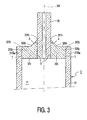
- Figs. 3 through 5 variant constructions are shown of the part of the discharge vessel situated near an end of the central cylindrical part before a relevant electrode and feedthrough conductor are provided.
- the parts corresponding to those shown in Figs. 1 and 2 are denoted by a corrresponding reference numeral.
- the end part 32b whose outside surface 320b is shaped like a truncated cone, has a foot 325b which is widened relative to the base of the cone.
- a difference between the embodiments of Fig. 2 and Fig. 3 is that, at the same dimension of the end, in the construction shown in Fig. 3, the end part has a smaller heat capacitance so that a smaller heat loss during operation of the lamp will take place.
- Figs. 4A, 4B and 4C have an end part 32b which is composed of 3 concentric tubular portions 326, 327, 328 which are interconnected in a gastight manner by sintering.
- the outside surface 320b of end part 32b has a stepped shape between the outside surface of the end part at the location of the projecting plug 321b and the outside surface at the location of the end 322b.
- tubular portions 326, 327, 328 form, on the side facing the discharge space 11, an end face 33a, 33b of the discharge space.
- the use of tubular portions 326, 327, 328 of substantially the same length causes the boundary of the discharge vessel at the location of the end part to be step-shaped just like the outside surface 320b. Particularly if heat losses should be minimized, this is an advantageous shape of the discharge vessel 3.
- the end part 32b is formed from a disc-shaped element 330 which is provided with a number, 4 in the example shown, of concentric discs 331 whose diameters decrease in a step-like manner.
- the discs are interconnected in a gastight manner by sintering. At the location of a central aperture through which the plug 35 projects, the discs are sintered to this plug in a gastight manner.
- Disc 330 is also connected in a gastight manner to the end 310b by means of a sintered connection T.
- a favorable aspect of the construction shown is that the discs 331 do not play a part in closing the discharge vessel in a gastight manner.
Landscapes
- Vessels And Coating Films For Discharge Lamps (AREA)
Claims (4)
- Hochdruck-Entladungslampe mit einem keramischen Entladungsgefäß (3), das einen Entladungsraum (11) umschließt, der eine ein Metallhalogenid enthaltende ionisierbare Füllung enthält und in dem eine erste und eine zweite Elektrode (4, 5) untergebracht sind, welches Entladungsgefäß eine Längsachse (300) hat und versehen ist mitdadurch gekennzeichnet, dass die Außenfläche des Endteils am Ort (321a, 321b) des hervorstehenden Stopfens in Bezug auf die Außenfläche am Ort (322a, 322b) des Endes in axialer Richtung vom Entladungsraum aus entfernt positioniert ist.einem zentralen zylindrischen Teil (31), der den Entladungsraum umschließt und der mit einem Ende (310a, 310b) versehen ist,einem Endteil (32a, 32b), der mit einer Außenfläche (320a, 320b) versehen ist und der den zylindrischen Teil am Ende (310a, 310b) gasdicht verschließt, undeinem hervorstehenden Stopfen (34, 35), der mittels einer Sinterverbindung (S) gasdicht mit dem Endteil verbunden ist und der einen zur ersten Elektrode (4) führenden Durchführleiter (40) mit Spiel umschließt, wobei der genannte Stopfen eine Dichtung aus einer Schmelzkeramik (10) enthält, durch die der Durchführleiter (40) austritt,
- Hochdruck-Entladungslampe nach Anspruch 1, dadurch gekennzeichnet, dass der Endteil (32a, 32b) monolithisch ist und die Außenfläche (320a, 320b) am Ort des hervorstehenden Stopfens (34, 35) mit der Längsachse (300) einen Winkel A bildet, welcher Winkel, in Grad ausgedrückt, die folgende Beziehung erfüllt
- Hochdruck-Entladungslampe nach Anspruch 1 oder 2, dadurch gekennzeichnet, dass der Endteil (32b) aus zumindest 2 konzentrischen röhrenförmigen Abschnitten (326, 327, 328) zusammengesetzt ist, die durch Sinterung gasdicht miteinander verbunden sind.
- Hochdruck-Entladungslampe nach Anspruch 1 oder 2, dadurch gekennzeichnet, dass die Außenfläche (320b) des Endteils (32b) die Form eines Kegelstumpfes hat, dessen Basis mit einem Fuß versehen ist.
Priority Applications (1)
| Application Number | Priority Date | Filing Date | Title |
|---|---|---|---|
| EP98955870A EP0960432B1 (de) | 1997-12-16 | 1998-12-07 | Hochdruckentladungslampe |
Applications Claiming Priority (4)
| Application Number | Priority Date | Filing Date | Title |
|---|---|---|---|
| EP97203958 | 1997-12-16 | ||
| EP97203958 | 1997-12-16 | ||
| PCT/IB1998/001979 WO1999031708A1 (en) | 1997-12-16 | 1998-12-07 | High-pressure discharge lamp |
| EP98955870A EP0960432B1 (de) | 1997-12-16 | 1998-12-07 | Hochdruckentladungslampe |
Publications (2)
| Publication Number | Publication Date |
|---|---|
| EP0960432A1 EP0960432A1 (de) | 1999-12-01 |
| EP0960432B1 true EP0960432B1 (de) | 2004-07-14 |
Family
ID=8229065
Family Applications (1)
| Application Number | Title | Priority Date | Filing Date |
|---|---|---|---|
| EP98955870A Expired - Lifetime EP0960432B1 (de) | 1997-12-16 | 1998-12-07 | Hochdruckentladungslampe |
Country Status (6)
| Country | Link |
|---|---|
| US (1) | US6259205B1 (de) |
| EP (1) | EP0960432B1 (de) |
| JP (1) | JP2001512623A (de) |
| CN (1) | CN1134823C (de) |
| DE (1) | DE69825035T2 (de) |
| WO (1) | WO1999031708A1 (de) |
Families Citing this family (8)
| Publication number | Priority date | Publication date | Assignee | Title |
|---|---|---|---|---|
| US6414436B1 (en) | 1999-02-01 | 2002-07-02 | Gem Lighting Llc | Sapphire high intensity discharge projector lamp |
| JP4613408B2 (ja) * | 1999-10-15 | 2011-01-19 | 日本碍子株式会社 | 高圧放電灯用発光管の製造方法 |
| WO2001067488A1 (en) * | 2000-03-08 | 2001-09-13 | Japan Storage Battery Co., Ltd. | Electric discharge lamp |
| JP3498072B2 (ja) * | 2001-06-25 | 2004-02-16 | 炳霖 ▲楊▼ | 放電ランプ用発光体 |
| KR101008530B1 (ko) * | 2002-11-25 | 2011-01-14 | 코닌클리케 필립스 일렉트로닉스 엔.브이. | 방전 용기, 가스-밀폐방식의 고압 버너, 상기 버너를 포함하는 램프 및 상기 램프를 제조하는 방법 |
| US7211954B2 (en) * | 2005-03-09 | 2007-05-01 | General Electric Company | Discharge tubes |
| US7279838B2 (en) * | 2005-03-09 | 2007-10-09 | General Electric Company | Discharge tubes |
| DE102006052761A1 (de) * | 2006-11-08 | 2008-05-15 | Patent-Treuhand-Gesellschaft für elektrische Glühlampen mbH | Keramisches Entladungsgefäß und Hochdruckentladungslampe mit einem derartigen Entladungsgefäß |
Family Cites Families (9)
| Publication number | Priority date | Publication date | Assignee | Title |
|---|---|---|---|---|
| US4208605A (en) * | 1977-11-14 | 1980-06-17 | General Electric Company | Alumina, calcia, baria sealing composition optionally modified with B2 3 |
| JPS6037645A (ja) * | 1983-08-10 | 1985-02-27 | Toshiba Corp | 金属蒸気放電灯 |
| JPS62170129A (ja) * | 1986-01-21 | 1987-07-27 | Ngk Insulators Ltd | 高圧金属蒸気放電灯用セラミツク発光管の製造法 |
| US5404078A (en) * | 1991-08-20 | 1995-04-04 | Patent-Treuhand-Gesellschaft Fur Elektrische Gluhlampen Mbh | High-pressure discharge lamp and method of manufacture |
| US5321335A (en) * | 1992-08-03 | 1994-06-14 | General Electric Company | Alumina, calcia, yttria sealing composition |
| US5424609A (en) | 1992-09-08 | 1995-06-13 | U.S. Philips Corporation | High-pressure discharge lamp |
| EP0587238B1 (de) * | 1992-09-08 | 2000-07-19 | Koninklijke Philips Electronics N.V. | Hochdruckentladungslampe |
| US5426343A (en) * | 1992-09-16 | 1995-06-20 | Gte Products Corporation | Sealing members for alumina arc tubes and method of making the same |
| JP3507179B2 (ja) * | 1995-01-13 | 2004-03-15 | 日本碍子株式会社 | 高圧放電灯 |
-
1998
- 1998-12-07 WO PCT/IB1998/001979 patent/WO1999031708A1/en not_active Ceased
- 1998-12-07 CN CNB988025795A patent/CN1134823C/zh not_active Expired - Fee Related
- 1998-12-07 JP JP53224999A patent/JP2001512623A/ja not_active Abandoned
- 1998-12-07 DE DE69825035T patent/DE69825035T2/de not_active Expired - Fee Related
- 1998-12-07 EP EP98955870A patent/EP0960432B1/de not_active Expired - Lifetime
- 1998-12-08 US US09/207,525 patent/US6259205B1/en not_active Expired - Fee Related
Also Published As
| Publication number | Publication date |
|---|---|
| US6259205B1 (en) | 2001-07-10 |
| DE69825035T2 (de) | 2005-08-25 |
| JP2001512623A (ja) | 2001-08-21 |
| DE69825035D1 (de) | 2004-08-19 |
| WO1999031708A1 (en) | 1999-06-24 |
| EP0960432A1 (de) | 1999-12-01 |
| CN1134823C (zh) | 2004-01-14 |
| CN1248342A (zh) | 2000-03-22 |
Similar Documents
| Publication | Publication Date | Title |
|---|---|---|
| US5424608A (en) | High-pressure discharge lamp with ceramic discharge vessel | |
| JP3723676B2 (ja) | 高圧放電ランプの設計方法 | |
| EP0759207B1 (de) | Hochdruckentladungslampe | |
| EP0926703B1 (de) | Metalldampfentladungslampe | |
| US5751111A (en) | High-pressure metal halide lamp | |
| US4160930A (en) | Electric discharge lamp with annular current conductor | |
| EP0960432B1 (de) | Hochdruckentladungslampe | |
| WO1998049715A1 (en) | High-pressure discharge lamp | |
| HU189969B (en) | Ceramic covering element for high-pressure discharge lamps | |
| US5808398A (en) | Metal halide lamp having specific volume pressure ratio | |
| US5015913A (en) | High-pressure discharge lamp, especially sodium vapor lamp | |
| US4766347A (en) | High-pressure discharge lamp having a lead-through with a protuberance | |
| US6617790B2 (en) | Metal halide lamp with ceramic discharge vessel | |
| US5008583A (en) | High-pressure discharge lamp | |
| US6856079B1 (en) | Ceramic discharge lamp arc tube seal | |
| US6969951B1 (en) | High pressure discharge vessel for an alumina high-intensity discharge lamp | |
| EP1160831B1 (de) | Entladungslampe | |
| US7164232B2 (en) | Seal for ceramic discharge lamp arc tube | |
| KR20070046186A (ko) | 램프 | |
| JP4210704B2 (ja) | 高圧放電ランプ | |
| JPH05334997A (ja) | 金属蒸気放電灯 | |
| JPH08273618A (ja) | セラミック放電灯 |
Legal Events
| Date | Code | Title | Description |
|---|---|---|---|
| PUAI | Public reference made under article 153(3) epc to a published international application that has entered the european phase |
Free format text: ORIGINAL CODE: 0009012 |
|
| AK | Designated contracting states |
Kind code of ref document: A1 Designated state(s): BE DE FR GB IT NL |
|
| 17P | Request for examination filed |
Effective date: 19991227 |
|
| 17Q | First examination report despatched |
Effective date: 20021022 |
|
| GRAP | Despatch of communication of intention to grant a patent |
Free format text: ORIGINAL CODE: EPIDOSNIGR1 |
|
| GRAS | Grant fee paid |
Free format text: ORIGINAL CODE: EPIDOSNIGR3 |
|
| GRAA | (expected) grant |
Free format text: ORIGINAL CODE: 0009210 |
|
| AK | Designated contracting states |
Kind code of ref document: B1 Designated state(s): BE DE FR GB IT NL |
|
| PG25 | Lapsed in a contracting state [announced via postgrant information from national office to epo] |
Ref country code: NL Free format text: LAPSE BECAUSE OF FAILURE TO SUBMIT A TRANSLATION OF THE DESCRIPTION OR TO PAY THE FEE WITHIN THE PRESCRIBED TIME-LIMIT Effective date: 20040714 Ref country code: IT Free format text: LAPSE BECAUSE OF FAILURE TO SUBMIT A TRANSLATION OF THE DESCRIPTION OR TO PAY THE FEE WITHIN THE PRESCRIBED TIME-LIMIT;WARNING: LAPSES OF ITALIAN PATENTS WITH EFFECTIVE DATE BEFORE 2007 MAY HAVE OCCURRED AT ANY TIME BEFORE 2007. THE CORRECT EFFECTIVE DATE MAY BE DIFFERENT FROM THE ONE RECORDED. Effective date: 20040714 |
|
| REG | Reference to a national code |
Ref country code: GB Ref legal event code: FG4D |
|
| REF | Corresponds to: |
Ref document number: 69825035 Country of ref document: DE Date of ref document: 20040819 Kind code of ref document: P |
|
| NLV1 | Nl: lapsed or annulled due to failure to fulfill the requirements of art. 29p and 29m of the patents act | ||
| ET | Fr: translation filed | ||
| PLBE | No opposition filed within time limit |
Free format text: ORIGINAL CODE: 0009261 |
|
| STAA | Information on the status of an ep patent application or granted ep patent |
Free format text: STATUS: NO OPPOSITION FILED WITHIN TIME LIMIT |
|
| 26N | No opposition filed |
Effective date: 20050415 |
|
| PGFP | Annual fee paid to national office [announced via postgrant information from national office to epo] |
Ref country code: BE Payment date: 20051125 Year of fee payment: 8 |
|
| PGFP | Annual fee paid to national office [announced via postgrant information from national office to epo] |
Ref country code: GB Payment date: 20051220 Year of fee payment: 8 |
|
| PGFP | Annual fee paid to national office [announced via postgrant information from national office to epo] |
Ref country code: FR Payment date: 20051227 Year of fee payment: 8 |
|
| PGFP | Annual fee paid to national office [announced via postgrant information from national office to epo] |
Ref country code: DE Payment date: 20060214 Year of fee payment: 8 |
|
| PG25 | Lapsed in a contracting state [announced via postgrant information from national office to epo] |
Ref country code: BE Free format text: LAPSE BECAUSE OF NON-PAYMENT OF DUE FEES Effective date: 20061231 |
|
| PG25 | Lapsed in a contracting state [announced via postgrant information from national office to epo] |
Ref country code: DE Free format text: LAPSE BECAUSE OF NON-PAYMENT OF DUE FEES Effective date: 20070703 |
|
| GBPC | Gb: european patent ceased through non-payment of renewal fee |
Effective date: 20061207 |
|
| REG | Reference to a national code |
Ref country code: FR Ref legal event code: ST Effective date: 20070831 |
|
| PG25 | Lapsed in a contracting state [announced via postgrant information from national office to epo] |
Ref country code: GB Free format text: LAPSE BECAUSE OF NON-PAYMENT OF DUE FEES Effective date: 20061207 |
|
| BERE | Be: lapsed |
Owner name: KONINKLIJKE *PHILIPS ELECTRONICS N.V. Effective date: 20061231 |
|
| PG25 | Lapsed in a contracting state [announced via postgrant information from national office to epo] |
Ref country code: FR Free format text: LAPSE BECAUSE OF NON-PAYMENT OF DUE FEES Effective date: 20070102 |