EP0960449B1 - Antenne helicoidale bifrequence - Google Patents
Antenne helicoidale bifrequence Download PDFInfo
- Publication number
- EP0960449B1 EP0960449B1 EP98961268A EP98961268A EP0960449B1 EP 0960449 B1 EP0960449 B1 EP 0960449B1 EP 98961268 A EP98961268 A EP 98961268A EP 98961268 A EP98961268 A EP 98961268A EP 0960449 B1 EP0960449 B1 EP 0960449B1
- Authority
- EP
- European Patent Office
- Prior art keywords
- antenna
- turn
- pitch
- turns
- helix
- Prior art date
- Legal status (The legal status is an assumption and is not a legal conclusion. Google has not performed a legal analysis and makes no representation as to the accuracy of the status listed.)
- Expired - Lifetime
Links
- 239000011295 pitch Substances 0.000 claims abstract description 39
- 239000004020 conductor Substances 0.000 claims abstract description 32
- 230000008878 coupling Effects 0.000 claims description 18
- 238000010168 coupling process Methods 0.000 claims description 18
- 238000005859 coupling reaction Methods 0.000 claims description 18
- 230000001413 cellular effect Effects 0.000 claims description 8
- 230000007423 decrease Effects 0.000 claims description 4
- 238000010079 rubber tapping Methods 0.000 description 8
- CNQCVBJFEGMYDW-UHFFFAOYSA-N lawrencium atom Chemical compound [Lr] CNQCVBJFEGMYDW-UHFFFAOYSA-N 0.000 description 5
- 238000004519 manufacturing process Methods 0.000 description 5
- 230000001681 protective effect Effects 0.000 description 4
- 238000005259 measurement Methods 0.000 description 3
- 238000004891 communication Methods 0.000 description 2
- IRLPACMLTUPBCL-KQYNXXCUSA-N 5'-adenylyl sulfate Chemical compound C1=NC=2C(N)=NC=NC=2N1[C@@H]1O[C@H](COP(O)(=O)OS(O)(=O)=O)[C@@H](O)[C@H]1O IRLPACMLTUPBCL-KQYNXXCUSA-N 0.000 description 1
- 239000003989 dielectric material Substances 0.000 description 1
- 230000004927 fusion Effects 0.000 description 1
- 239000003292 glue Substances 0.000 description 1
- 230000003993 interaction Effects 0.000 description 1
- 239000000463 material Substances 0.000 description 1
- 239000002184 metal Substances 0.000 description 1
- 238000000034 method Methods 0.000 description 1
- 239000002991 molded plastic Substances 0.000 description 1
- 238000003466 welding Methods 0.000 description 1
Images


Classifications
-
- H—ELECTRICITY
- H01—ELECTRIC ELEMENTS
- H01Q—ANTENNAS, i.e. RADIO AERIALS
- H01Q1/00—Details of, or arrangements associated with, antennas
- H01Q1/36—Structural form of radiating elements, e.g. cone, spiral, umbrella; Particular materials used therewith
- H01Q1/362—Structural form of radiating elements, e.g. cone, spiral, umbrella; Particular materials used therewith for broadside radiating helical antennas
-
- H—ELECTRICITY
- H01—ELECTRIC ELEMENTS
- H01Q—ANTENNAS, i.e. RADIO AERIALS
- H01Q5/00—Arrangements for simultaneous operation of antennas on two or more different wavebands, e.g. dual-band or multi-band arrangements
- H01Q5/30—Arrangements for providing operation on different wavebands
- H01Q5/307—Individual or coupled radiating elements, each element being fed in an unspecified way
- H01Q5/342—Individual or coupled radiating elements, each element being fed in an unspecified way for different propagation modes
- H01Q5/357—Individual or coupled radiating elements, each element being fed in an unspecified way for different propagation modes using a single feed point
Definitions
- the invention relates in general to antenna structures in radio apparatus.
- the invention relates to an antenna structure which has two resonating frequencies different from each other.
- This patent application uses a mobile phone as an example of a radio apparatus.
- the operating frequencies of the Global System for Mobile Telecommunications are in the 890-960 MHz range
- the operating frequencies of the Japanese Digital Cellular (JDC) system are in the 800 MHz and 1500 MHz bands
- the operating frequencies of the Personal Communication Network (PCN) are in the 1710-1880 MHz range
- those of the Personal Communication System (PCS) in the 1850-1990 MHz range.
- the operating frequencies of the American AMPS mobile phone system are between 824 MHz and 894 MHz and those of the Digital European Cordless Telephone (DECT) system in the 1880-1900 MHz range.
- DECT Digital European Cordless Telephone
- a particular antenna can be used only in a mobile phone designed for a single-frequency cellular radio system. In some cases, however, it is desirable that one and the same phone could be used in some other frequency range, too. In addition to other suitable RF parts, a working antenna arrangement is then needed.
- US Patent 4,442,438 discloses an antenna structure resonating at two frequencies, comprising, as shown in Fig. 1, two helices 101, 102 and one whip element 103.
- the helices 101 and 102 are positioned one after the other and their adjacent ends 104 and 105 constitute the feed point of the combined structure.
- the whip element 103 is partly inside the upper helix 101 and its feed point 106 is at its lower end.
- An RF signal is brought to the feed point 106 via a coaxial conductor 107 coinciding with the symmetry axis of the structure and traveling through the lower helix 102.
- the feed point 106 of the whip element is coupled to the lower end 104 of the upper helix, and the lower helix is coupled at its upper end 105 to the conductive and grounded shroud of the coaxial conductor 107.
- the structure's first resonating frequency is the resonating frequency of the combined structure of helices 101 and 102; 827 MHz in the illustrative embodiment.
- the second resonating frequency of the structure is the common resonating frequency of the upper helix 101 and the whip element 103; 850 MHz in the illustrative embodiment.
- helix 101 and whip element 103 are such that they have substantially the same resonating frequency.
- the structure disclosed by the US Patent is relatively complex. From the manufacturing standpoint, the most difficult part in the structure is the feed point arrangement at the middle of the antenna, where the lower end 106 of the whip element and the lower end 104 of the upper helix have to be galvanically coupled, and the lower helix has to be coupled at its upper end 105 to the shroud of the coaxial conductor feeding the whip element.
- the difference between the two resonating frequencies achieved by the structure is small because the dimensions of the upper helix 101 and the whip element 103 have to be such that they have substantially the same common resonating frequency, so the structure cannot be applied to a phone operating at the GSM and PCN frequencies, for example.
- an object of the invention is to broaden the resonating frequency area of the mobile phone antenna such that it would better cover the whole frequency range in one cellular radio system.
- FI patent application 963275 discloses a dual-frequency antenna structure according to Fig. 2 in which there is at a certain point between the ends of a helix antenna 201 wound into a cylindrical coil a coupling part 202 for coupling to a second antenna element 203.
- the cylindrical coil conductor 201 which is the first antenna element in the antenna, comprises in the direction of its longitudinal axis a lower part 204 and an upper part 205, and the second antenna element 203 is connected to the cylindrical coil conductor through a fixed coupling at the coupling point 202 between the lower and upper parts.
- the two radiating antenna elements of the structure have a common lower part up to the branching point consisting of the coupling part, from which point on the electrical lengths of the antenna elements are different.
- the first resonating frequency of the combined antenna structure is determined by the total electrical length of the common lower part of the antenna elements and the upper part of the first antenna element.
- the second resonating frequency is determined by the total electrical length of the common lower part of the antenna elements and the upper part of the second antenna element.
- the resonating frequencies are affected by the mutual coupling of the antenna elements and the fact that the antenna elements are electrically conductive bodies in the near fields of one another so that they put a load on each other.
- the antenna structure according to Fig. 2 is relatively difficult to precisely dimension to the desired frequencies since the coupling point between the antenna elements requires quite accurate positioning.
- the electrical coupling in the coupling point easily becomes unreliable.
- FI patent application 970297 discloses an antenna according to the principle illustrated in Fig. 3 wherein an antenna element 301 has a first end and a second end and a tapping point 302 which is located at a certain point between the ends of the antenna element.
- the tapping point divides the antenna element asymmetrically such that the electrical length from the tapping point to the upper end is considerably greater than the electrical length from the tapping point to the lower end.
- the feed conductor 303 of the antenna which connects the antenna element electrically to a radio apparatus, is coupled to the antenna element at the tapping point.
- a substantial portion of the feed conductor also serves as a radiating element because the feed conductor is electrically unshielded, i.e.
- the total electrical length of the antenna structure at a first operating frequency is the sum of the electrical lengths of the feed conductor 303 and the portion extending from the tapping point 302 to a first end of the antenna element 301.
- the total electrical length of the antenna structure at a second operating frequency is the sum of the electrical lengths of the feed conductor 303 and the portion extending from the tapping point 302 to a second end of the antenna element 301.
- the antenna element 301 may be a helix, a straight conductor or a combination of those.
- the disadvantage of this antenna structure is the difficulty in manufacturing the antenna structure such that the tapping point 302 will be sturdy.
- the objects of the invention are achieved by using as an antenna element a helix the pitch of which decreases when moving away from the feed point.
- the antenna according to the invention comprises a cylindrical coil conductor having a turn A and turn B and other turns between them.
- the antenna is characterized in that the pitch of turn A does not equal the pitch of turn B and the pitches of the other turns between turn A and turn B are arranged according to the magnitude between the pitch of turn A and the pitch of turn B.
- a conductive body may have multiple resonating frequencies the lowest one of which is the so-called fundamental frequency, the rest being harmonic frequencies.
- the invention is based on the observation that the resonating frequency of a cylindrical coil conductor, or helix, is changed when the dimensional parameters of the helix are changed in the various parts of the structure.
- the electrical length of the helix conductor determines the fundamental frequency.
- the distance between the ends of a turn in the direction of the longitudinal axis of the helix is called a pitch.
- the pitch of the helix at various points and other parameters are suitably selected, the resonating frequencies will be at such positions on the frequency axis that the structure can be used in two cellular radio system frequency ranges.
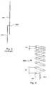
- Fig. 4 shows a longitudinal section of a helix antenna 400 having seven turns. Viewing from the feed point 401 the pitch x1 of the first turn is greater than the pitch x2 of the last turn. The pitches of the other turns decrease evenly from the first turn toward the last turn.
- the helix antenna is shown in the upright position but the invention does not limit the use or manufacture of the helix antenna according to the invention in any particular position.
- a feed point 401 and the leg 402 of the helix can be realised in such a manner that the helix conductor is bent into the shape of the black line shown in the Figure.
- the helix is connected at its bottom end, with respect to the position shown, to a coupling part having a cylindrical hollow into which the lowest turns of the helix are inserted.
- the bottom end of the helix may have a support thread (not shown) more densely wound than the rest of the helix, said support thread, when connected to the coupling part, will not serve as radiating element as the electrically conductive coupling part short circuits the turns of the support thread.
- Other known methods for creating a feed point 401 and for connecting the helix antenna to a radio apparatus can be used, too.
- Fig. 5 illustrates a measurement of the so-called s11 coefficient, or reflection coefficient, with the horizontal axis representing the frequency range of 700 MHz to 2100 MHz and the vertical axis representing the value of the reflection coefficient in units of decibel.
- the measurement concerns an antenna according to Fig. 4.
- the triangular symbol on the vertical axis represents 0 dB, one step on the vertical axis equals 5 dB and one step on the horizontal axis equals 140 MHz.
- the reflection coefficient tells how much of the radio-frequency power fed to the antenna via the feed point is reflected back. A low value of the reflection coefficient at a certain frequency means the antenna is suitable for that frequency.
- the antenna has two resonating frequency ranges wherein the value of the reflection coefficient is clearly smaller than -10 dB.
- the first resonating frequency range (s11 ⁇ -10 dB) is about 880 MHz to 960 MHz
- the second resonating frequency range (s11 ⁇ -10 dB) is about 1730 MHz to 1800 MHz.
- the turns of the helix may also become thinner, i.e. the pitch may increase from the feed point on.
- the resonating frequency ranges of the antenna according to the invention depend among other things on the thickness of the helix conductor, pitch of the turns and on the diameter of the helix.
- the table below shows some measurement results for helices H1, H2, H3, H5, H6, H7, H8, H9, and H10 in which the height of the helix from the beginning of the first turn to the end of the last turn is 22 mm, the length of the leg (402 in Fig.
- the thickness of the helix conductor is 0.9 mm, as well as for a helix H11 in which the height of the helix is 16 mm, thickness of the helix conductor is 0.9 mm, height of the leg is 6 mm and the diameter of the leg is 3 mm, as well as for a helix H12 in which the height of the helix is 16 mm, thickness of the helix conductor is 0.8 mm, height of the leg is 6 mm and the diameter of the leg is 3 mm.
- the lower and upper diameter values shown in the table are inner diameters and the frequencies f1 and f3 are the resonating frequencies in the frequency ranges for which the helix is suitable.
- H1 H2 H3 H5 (decr. pitch) Lower diameter/mm 7.1x7.1 2x2 3x3 7.1 Upper diameter/mm 7.1x7.1 8.2x8.2 14x14 7.1 Pitch / mm 4 2.5 5 5+4.5+4+3.5x2.3+2 Outer volume / mm 3 1110 620 1530 1110 Freq. / Real part of imp.
- the pitch of the helices H1, H2, H3, H9, H10 and H11 is the same in all turns, i.e. they are not in accordance with the invention.
- the diameters of the turns change between the feed point and the second end of the helix: the lower diameter refers to the diameter nearest to the feed point.
- the values of the ratio f3/f1 printed in boldface emphasize helices H5, H6 and H 12 which from the resonating frequency standpoint are especially suitable as antennas for a GSM/PCN dual-mode phone.
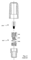
- Fig. 6 shows in the form of a longitudinal section an antenna 600 according to the invention comprising a helix conductor 601, coupling part 602 made of metal or another electrically conductive material, and a protective housing 603.
- the outer surface of the coupling part 602 has threads 604 whereby the antenna 600 can be mechanically and electrically coupled to a radio apparatus (not shown).
- the lower part of the helix conductor has a dense support thread 605 whereby the helix conductor 601 is attached to a cylindrical hollow in the coupling part 602.
- the support thread does not belong to the radiating portion of the antenna.
- the protective housing 603 is made of a dielectric material, preferably injection-molded plastic, and it can be attached to the coupling part with glue or by means of fusion welding.
- the protective housing 603 may include components (not shown) supporting the helix conductor 601, such as a cylindrical pin pushed inside the helix from the top.
- the present invention is not limited to the exemplary embodiments described here, nor to any particular application but can be used in antennas in different applications and at different frequencies, advantageously radio frequencies such as UHF and VHF.
- the structure is advantageously used in antennas of mobile phones.
- the structure may be modified within the scope of the invention defined by the claims set forth below.
- the pitches of the first and last turns of the helix may even be almost identical if there is a second turn between them having a pitch unequal to that of the first turn, if then there are other turns between the first and said second turn where the pitch changes in a regular manner.
Landscapes
- Details Of Aerials (AREA)
- Support Of Aerials (AREA)
Abstract
Claims (6)
- Antenne (400 ; 600) destinée à transmettre et à recevoir des signaux radio fréquence, comprenant un conducteur de bobine cylindrique (601) ayant une spire A et une spire B et d'autres spires entre elles, caractérisée en ce que le pas (x1) de ladite spire A est non égal au pas (x2) de ladite spire B, le pas de chaque spire entre les spires A et B est non égal aux pas des autres spires entre les spires A et B, les pas des autres spires entre les spires A et B sont d'un ordre de grandeur entre le pas de la spire A et le pas de la spire B, et l'antenne possède deux bandes de fréquence de résonance.
- Antenne selon la revendication 1, caractérisée en ce que la spire A est la première spire du conducteur de bobine cylindrique appartenant à la partie rayonnante de l'antenne au niveau de sa première extrémité, et le spire B est la dernière spire du conducteur de bobine cylindrique au niveau de sa seconde extrémité, si bien que la première spire comprend le point d'alimentation (401) de l'antenne.
- Antenne selon la revendication 2, caractérisée en ce que le pas (x2) de la spire B est plus petit que le pas (x1) de la spire A, si bien que le pas des spires dans le conducteur de bobine cylindrique diminue lorsqu'il est déplacé en s'éloignant du point d'alimentation (401).
- Antenne selon la revendication 1, caractérisée en ce que sa première bande de fréquence de résonance est sensiblement identique à une première bande de fréquence de fonctionnement d'un système radio cellulaire, et dont la seconde est sensiblement identique à une seconde bande de fréquence de fonctionnement d'un système radio cellulaire.
- Antenne selon la revendication 1, caractérisée en ce qu'elle comprend une partie de couplage (602) et dans celle-ci un creux cylindrique dans lequel une première extrémité du conducteur de bobine cylindrique (601) est adaptée.
- Antenne selon la revendication 5, caractérisée en ce que la première extrémité du conducteur de bobine cylindrique (601) comprend un filetage de support (605) à adapter dans un creux cylindrique de la partie de couplage.
Applications Claiming Priority (3)
| Application Number | Priority Date | Filing Date | Title |
|---|---|---|---|
| FI974527 | 1997-12-16 | ||
| FI974527A FI111884B (fi) | 1997-12-16 | 1997-12-16 | Kahden taajuuden heliksiantenni |
| PCT/FI1998/000982 WO1999031756A1 (fr) | 1997-12-16 | 1998-12-15 | Antenne helicoidale bifrequence |
Publications (2)
| Publication Number | Publication Date |
|---|---|
| EP0960449A1 EP0960449A1 (fr) | 1999-12-01 |
| EP0960449B1 true EP0960449B1 (fr) | 2005-03-16 |
Family
ID=8550139
Family Applications (1)
| Application Number | Title | Priority Date | Filing Date |
|---|---|---|---|
| EP98961268A Expired - Lifetime EP0960449B1 (fr) | 1997-12-16 | 1998-12-15 | Antenne helicoidale bifrequence |
Country Status (6)
| Country | Link |
|---|---|
| US (1) | US6340954B1 (fr) |
| EP (1) | EP0960449B1 (fr) |
| AU (1) | AU1673299A (fr) |
| DE (1) | DE69829362T2 (fr) |
| FI (1) | FI111884B (fr) |
| WO (1) | WO1999031756A1 (fr) |
Families Citing this family (42)
| Publication number | Priority date | Publication date | Assignee | Title |
|---|---|---|---|---|
| DE10037472C2 (de) * | 2000-08-01 | 2002-09-26 | Siemens Ag | Verfahren zum Einbau einer Antenne |
| JP2002359514A (ja) * | 2001-05-31 | 2002-12-13 | Anten Corp | ヘリカルアンテナ |
| US6545649B1 (en) * | 2001-10-31 | 2003-04-08 | Seavey Engineering Associates, Inc. | Low backlobe variable pitch quadrifilar helix antenna system for mobile satellite applications |
| GB2389232B (en) * | 2002-06-01 | 2004-10-27 | Motorola Inc | Multi-frequency band antenna and methods of tuning and manufacture |
| TWI283086B (en) * | 2004-09-08 | 2007-06-21 | Inventec Appliances Corp | Multi-mode and multi-band combing antenna |
| FI20055420A0 (fi) * | 2005-07-25 | 2005-07-25 | Lk Products Oy | Säädettävä monikaista antenni |
| FI119009B (fi) * | 2005-10-03 | 2008-06-13 | Pulse Finland Oy | Monikaistainen antennijärjestelmä |
| FI118782B (fi) | 2005-10-14 | 2008-03-14 | Pulse Finland Oy | Säädettävä antenni |
| US8618990B2 (en) | 2011-04-13 | 2013-12-31 | Pulse Finland Oy | Wideband antenna and methods |
| FI20075269A0 (fi) * | 2007-04-19 | 2007-04-19 | Pulse Finland Oy | Menetelmä ja järjestely antennin sovittamiseksi |
| FI120427B (fi) | 2007-08-30 | 2009-10-15 | Pulse Finland Oy | Säädettävä monikaista-antenni |
| US8248323B2 (en) * | 2008-05-30 | 2012-08-21 | Motorola Solutions, Inc. | Antenna and method of forming same |
| EP2461421B1 (fr) * | 2009-07-31 | 2019-03-13 | Hytera Communications Corp., Ltd. | Antenne à deux fréquences |
| FI20096134A0 (fi) | 2009-11-03 | 2009-11-03 | Pulse Finland Oy | Säädettävä antenni |
| FI20096251A0 (sv) | 2009-11-27 | 2009-11-27 | Pulse Finland Oy | MIMO-antenn |
| US8847833B2 (en) * | 2009-12-29 | 2014-09-30 | Pulse Finland Oy | Loop resonator apparatus and methods for enhanced field control |
| US9342716B2 (en) * | 2010-02-04 | 2016-05-17 | Carefusion 303, Inc. | Software-defined multi-mode RFID read devices |
| FI20105158A7 (fi) | 2010-02-18 | 2011-08-19 | Pulse Finland Oy | Kuorisäteilijällä varustettu antenni |
| US9406998B2 (en) | 2010-04-21 | 2016-08-02 | Pulse Finland Oy | Distributed multiband antenna and methods |
| FI20115072A0 (fi) | 2011-01-25 | 2011-01-25 | Pulse Finland Oy | Moniresonanssiantenni, -antennimoduuli ja radiolaite |
| US9673507B2 (en) | 2011-02-11 | 2017-06-06 | Pulse Finland Oy | Chassis-excited antenna apparatus and methods |
| US8648752B2 (en) | 2011-02-11 | 2014-02-11 | Pulse Finland Oy | Chassis-excited antenna apparatus and methods |
| US8866689B2 (en) | 2011-07-07 | 2014-10-21 | Pulse Finland Oy | Multi-band antenna and methods for long term evolution wireless system |
| US9450291B2 (en) | 2011-07-25 | 2016-09-20 | Pulse Finland Oy | Multiband slot loop antenna apparatus and methods |
| US9123990B2 (en) | 2011-10-07 | 2015-09-01 | Pulse Finland Oy | Multi-feed antenna apparatus and methods |
| US9531058B2 (en) | 2011-12-20 | 2016-12-27 | Pulse Finland Oy | Loosely-coupled radio antenna apparatus and methods |
| US9484619B2 (en) | 2011-12-21 | 2016-11-01 | Pulse Finland Oy | Switchable diversity antenna apparatus and methods |
| US8988296B2 (en) | 2012-04-04 | 2015-03-24 | Pulse Finland Oy | Compact polarized antenna and methods |
| KR20130134658A (ko) * | 2012-05-31 | 2013-12-10 | 삼성전자주식회사 | 방사체 분리형 안테나 장치 |
| US9979078B2 (en) | 2012-10-25 | 2018-05-22 | Pulse Finland Oy | Modular cell antenna apparatus and methods |
| US10069209B2 (en) | 2012-11-06 | 2018-09-04 | Pulse Finland Oy | Capacitively coupled antenna apparatus and methods |
| US10079428B2 (en) | 2013-03-11 | 2018-09-18 | Pulse Finland Oy | Coupled antenna structure and methods |
| US9647338B2 (en) | 2013-03-11 | 2017-05-09 | Pulse Finland Oy | Coupled antenna structure and methods |
| WO2014193922A1 (fr) | 2013-05-28 | 2014-12-04 | University Of Florida Research Foundation, Inc. | Antenne en hélice à double fonction |
| US9634383B2 (en) | 2013-06-26 | 2017-04-25 | Pulse Finland Oy | Galvanically separated non-interacting antenna sector apparatus and methods |
| US9680212B2 (en) | 2013-11-20 | 2017-06-13 | Pulse Finland Oy | Capacitive grounding methods and apparatus for mobile devices |
| US9590308B2 (en) | 2013-12-03 | 2017-03-07 | Pulse Electronics, Inc. | Reduced surface area antenna apparatus and mobile communications devices incorporating the same |
| US9350081B2 (en) | 2014-01-14 | 2016-05-24 | Pulse Finland Oy | Switchable multi-radiator high band antenna apparatus |
| US9973228B2 (en) | 2014-08-26 | 2018-05-15 | Pulse Finland Oy | Antenna apparatus with an integrated proximity sensor and methods |
| US9948002B2 (en) | 2014-08-26 | 2018-04-17 | Pulse Finland Oy | Antenna apparatus with an integrated proximity sensor and methods |
| US9722308B2 (en) | 2014-08-28 | 2017-08-01 | Pulse Finland Oy | Low passive intermodulation distributed antenna system for multiple-input multiple-output systems and methods of use |
| US9906260B2 (en) | 2015-07-30 | 2018-02-27 | Pulse Finland Oy | Sensor-based closed loop antenna swapping apparatus and methods |
Family Cites Families (15)
| Publication number | Priority date | Publication date | Assignee | Title |
|---|---|---|---|---|
| US3852759A (en) * | 1960-04-01 | 1974-12-03 | Itt | Broadband tunable antenna |
| US4161737A (en) * | 1977-10-03 | 1979-07-17 | Albright Eugene A | Helical antenna |
| US4169267A (en) | 1978-06-19 | 1979-09-25 | The United States Of America As Represented By The Secretary Of The Air Force | Broadband helical antennas |
| US4442438A (en) * | 1982-03-29 | 1984-04-10 | Motorola, Inc. | Helical antenna structure capable of resonating at two different frequencies |
| CA1257694A (fr) | 1985-08-05 | 1989-07-18 | Hisamatsu Nakano | Systeme d'antenne |
| CA2061743C (fr) | 1992-02-24 | 1996-05-14 | Ems Technologies Canada, Ltd. | Antenne helicoidale a charge terminale |
| JP3317521B2 (ja) * | 1992-07-06 | 2002-08-26 | 原田工業株式会社 | 衛星通信用ヘリカルアンテナの製造方法 |
| SE512062C2 (sv) | 1993-07-14 | 2000-01-17 | Ericsson Ge Mobile Communicat | Förfarande och anordning för att förbättra effektivitet och bandbredd för en antenn på en bärbar utrustning |
| FR2711277B1 (fr) | 1993-10-14 | 1995-11-10 | Alcatel Mobile Comm France | Antenne du type pour dispositif radio portable, procédé de fabrication d'une telle antenne et dispositif radio portable comportant une telle antenne. |
| US5436633A (en) * | 1993-10-25 | 1995-07-25 | Liu; An-Shuenn | Adjustable antenna assembly for a portable telephone |
| US5489916A (en) * | 1994-08-26 | 1996-02-06 | Westinghouse Electric Corp. | Helical antenna having adjustable beam angle |
| FI98165C (fi) * | 1995-06-05 | 1997-04-25 | Lk Products Oy | Kaksitoiminen antenni |
| FI99219C (fi) * | 1995-06-06 | 1997-10-27 | Nokia Mobile Phones Ltd | Kahdella taajuusalueella toimiva antenni |
| US6112102A (en) | 1996-10-04 | 2000-08-29 | Telefonaktiebolaget Lm Ericsson | Multi-band non-uniform helical antennas |
| US5963871A (en) * | 1996-10-04 | 1999-10-05 | Telefonaktiebolaget Lm Ericsson | Retractable multi-band antennas |
-
1997
- 1997-12-16 FI FI974527A patent/FI111884B/fi not_active IP Right Cessation
-
1998
- 1998-12-15 WO PCT/FI1998/000982 patent/WO1999031756A1/fr not_active Ceased
- 1998-12-15 DE DE69829362T patent/DE69829362T2/de not_active Expired - Lifetime
- 1998-12-15 AU AU16732/99A patent/AU1673299A/en not_active Abandoned
- 1998-12-15 US US09/355,022 patent/US6340954B1/en not_active Expired - Fee Related
- 1998-12-15 EP EP98961268A patent/EP0960449B1/fr not_active Expired - Lifetime
Also Published As
| Publication number | Publication date |
|---|---|
| FI111884B (fi) | 2003-09-30 |
| FI974527A0 (fi) | 1997-12-16 |
| DE69829362D1 (de) | 2005-04-21 |
| AU1673299A (en) | 1999-07-05 |
| DE69829362T2 (de) | 2006-04-06 |
| WO1999031756A1 (fr) | 1999-06-24 |
| WO1999031756B1 (fr) | 1999-09-02 |
| US6340954B1 (en) | 2002-01-22 |
| FI974527L (fi) | 1999-06-17 |
| EP0960449A1 (fr) | 1999-12-01 |
Similar Documents
| Publication | Publication Date | Title |
|---|---|---|
| US6340954B1 (en) | Dual-frequency helix antenna | |
| EP0855759B1 (fr) | Antenne simple pour deux fréquences | |
| US6016130A (en) | Dual-frequency antenna | |
| US6054966A (en) | Antenna operating in two frequency ranges | |
| KR100446790B1 (ko) | 유전체가 내재된 안테나 | |
| FI98165C (fi) | Kaksitoiminen antenni | |
| US6037906A (en) | BroadBand aerial means | |
| KR100356196B1 (ko) | 2주파 대응 안테나 장치 및 이를 사용한 이동 통신기기 | |
| US7551145B2 (en) | Slot antenna | |
| US6710752B2 (en) | Helical antenna | |
| US6611691B1 (en) | Antenna adapted to operate in a plurality of frequency bands | |
| US6057807A (en) | Dual band antenna means incorporating helical and elongated radiating structures | |
| CA2074015C (fr) | Antenne miniature | |
| US6384798B1 (en) | Quadrifilar antenna | |
| JP2001352212A (ja) | アンテナ装置およびそれを用いた無線装置 | |
| WO1997018601A1 (fr) | Antenne a double bande | |
| JP2000509926A (ja) | 整合手段を有するアンテナ装置 | |
| WO2010077574A2 (fr) | Antennes omnidirectionnelles à gain élevé multibande | |
| US12027765B2 (en) | Corrugated ground plane apparatus for an antenna | |
| CA2291773C (fr) | Ensemble antenne et dispositif radio mobile utilisant ladite antenne | |
| GB2335312A (en) | An antenna adapted to operate in a plurality of frequency bands | |
| WO2001020716A1 (fr) | Systeme d'antenne et procede servant a reduire la taille du fouet dudit systeme d'antenne | |
| JPH05343907A (ja) | 可変長ホイップアンテナ | |
| KR20240078258A (ko) | 크로스 다이폴 안테나 |
Legal Events
| Date | Code | Title | Description |
|---|---|---|---|
| PUAI | Public reference made under article 153(3) epc to a published international application that has entered the european phase |
Free format text: ORIGINAL CODE: 0009012 |
|
| 17P | Request for examination filed |
Effective date: 19990809 |
|
| AK | Designated contracting states |
Kind code of ref document: A1 Designated state(s): DE FR GB IT SE |
|
| RAP1 | Party data changed (applicant data changed or rights of an application transferred) |
Owner name: FILTRONIC LK OY |
|
| GRAP | Despatch of communication of intention to grant a patent |
Free format text: ORIGINAL CODE: EPIDOSNIGR1 |
|
| GRAS | Grant fee paid |
Free format text: ORIGINAL CODE: EPIDOSNIGR3 |
|
| GRAA | (expected) grant |
Free format text: ORIGINAL CODE: 0009210 |
|
| RIN1 | Information on inventor provided before grant (corrected) |
Inventor name: PUURUNEN, PERTTI Inventor name: BORDI, MIKA Inventor name: KUITTINEN, TERO Inventor name: ANNAMAA, PETTERI |
|
| AK | Designated contracting states |
Kind code of ref document: B1 Designated state(s): DE FR GB IT SE |
|
| PG25 | Lapsed in a contracting state [announced via postgrant information from national office to epo] |
Ref country code: IT Free format text: LAPSE BECAUSE OF FAILURE TO SUBMIT A TRANSLATION OF THE DESCRIPTION OR TO PAY THE FEE WITHIN THE PRESCRIBED TIME-LIMIT;WARNING: LAPSES OF ITALIAN PATENTS WITH EFFECTIVE DATE BEFORE 2007 MAY HAVE OCCURRED AT ANY TIME BEFORE 2007. THE CORRECT EFFECTIVE DATE MAY BE DIFFERENT FROM THE ONE RECORDED. Effective date: 20050316 |
|
| REG | Reference to a national code |
Ref country code: GB Ref legal event code: FG4D |
|
| REF | Corresponds to: |
Ref document number: 69829362 Country of ref document: DE Date of ref document: 20050421 Kind code of ref document: P |
|
| REG | Reference to a national code |
Ref country code: SE Ref legal event code: TRGR |
|
| REG | Reference to a national code |
Ref country code: GB Ref legal event code: 732E |
|
| PLBE | No opposition filed within time limit |
Free format text: ORIGINAL CODE: 0009261 |
|
| STAA | Information on the status of an ep patent application or granted ep patent |
Free format text: STATUS: NO OPPOSITION FILED WITHIN TIME LIMIT |
|
| REG | Reference to a national code |
Ref country code: FR Ref legal event code: TP |
|
| ET | Fr: translation filed | ||
| 26N | No opposition filed |
Effective date: 20051219 |
|
| REG | Reference to a national code |
Ref country code: FR Ref legal event code: CD |
|
| PGFP | Annual fee paid to national office [announced via postgrant information from national office to epo] |
Ref country code: SE Payment date: 20091207 Year of fee payment: 12 |
|
| PGFP | Annual fee paid to national office [announced via postgrant information from national office to epo] |
Ref country code: GB Payment date: 20091209 Year of fee payment: 12 Ref country code: FR Payment date: 20091221 Year of fee payment: 12 |
|
| PGFP | Annual fee paid to national office [announced via postgrant information from national office to epo] |
Ref country code: DE Payment date: 20091222 Year of fee payment: 12 |
|
| GBPC | Gb: european patent ceased through non-payment of renewal fee |
Effective date: 20101215 |
|
| REG | Reference to a national code |
Ref country code: FR Ref legal event code: ST Effective date: 20110831 |
|
| REG | Reference to a national code |
Ref country code: SE Ref legal event code: EUG |
|
| PG25 | Lapsed in a contracting state [announced via postgrant information from national office to epo] |
Ref country code: SE Free format text: LAPSE BECAUSE OF NON-PAYMENT OF DUE FEES Effective date: 20101216 |
|
| PG25 | Lapsed in a contracting state [announced via postgrant information from national office to epo] |
Ref country code: FR Free format text: LAPSE BECAUSE OF NON-PAYMENT OF DUE FEES Effective date: 20110103 |
|
| REG | Reference to a national code |
Ref country code: DE Ref legal event code: R119 Ref document number: 69829362 Country of ref document: DE Effective date: 20110701 |
|
| PG25 | Lapsed in a contracting state [announced via postgrant information from national office to epo] |
Ref country code: DE Free format text: LAPSE BECAUSE OF NON-PAYMENT OF DUE FEES Effective date: 20110701 Ref country code: GB Free format text: LAPSE BECAUSE OF NON-PAYMENT OF DUE FEES Effective date: 20101215 |