EP0960576B1 - Vorrichtung zum Überführen von Stabförmigen artikeln - Google Patents
Vorrichtung zum Überführen von Stabförmigen artikeln Download PDFInfo
- Publication number
- EP0960576B1 EP0960576B1 EP98304186A EP98304186A EP0960576B1 EP 0960576 B1 EP0960576 B1 EP 0960576B1 EP 98304186 A EP98304186 A EP 98304186A EP 98304186 A EP98304186 A EP 98304186A EP 0960576 B1 EP0960576 B1 EP 0960576B1
- Authority
- EP
- European Patent Office
- Prior art keywords
- suction
- kicker
- rod
- housing
- passageway
- Prior art date
- Legal status (The legal status is an assumption and is not a legal conclusion. Google has not performed a legal analysis and makes no representation as to the accuracy of the status listed.)
- Expired - Lifetime
Links
- 230000002093 peripheral effect Effects 0.000 claims description 15
- 241000208125 Nicotiana Species 0.000 description 7
- 235000002637 Nicotiana tabacum Nutrition 0.000 description 7
- 238000004519 manufacturing process Methods 0.000 description 4
- 241000239290 Araneae Species 0.000 description 3
- 230000000717 retained effect Effects 0.000 description 2
- 235000019504 cigarettes Nutrition 0.000 description 1
- 230000003292 diminished effect Effects 0.000 description 1
- 230000000694 effects Effects 0.000 description 1
- 230000002401 inhibitory effect Effects 0.000 description 1
- 230000000670 limiting effect Effects 0.000 description 1
- 239000007787 solid Substances 0.000 description 1
- 230000003068 static effect Effects 0.000 description 1
Images


Classifications
-
- A—HUMAN NECESSITIES
- A24—TOBACCO; CIGARS; CIGARETTES; SIMULATED SMOKING DEVICES; SMOKERS' REQUISITES
- A24C—MACHINES FOR MAKING CIGARS OR CIGARETTES
- A24C5/00—Making cigarettes; Making tipping materials for, or attaching filters or mouthpieces to, cigars or cigarettes
- A24C5/32—Separating, ordering, counting or examining cigarettes; Regulating the feeding of tobacco according to rod or cigarette condition
- A24C5/322—Transporting cigarettes during manufacturing
- A24C5/326—Transporting cigarettes during manufacturing with lateral transferring means
Definitions
- This invention relates to a rod transfer apparatus. More specifically it is concerned with a kicker apparatus for removing tobacco rods or filters from a manufacturing line.
- Kickers are well known (See US-A-3 039 589) and have been used for many years, for example to pick finished tobacco rods off a rod maker and to pass them to a transfer which in turn passes them to a filter tipper.
- Known kickers include in-line or straight kickers which accelerate the rod in the line of the vee-rail of the rod maker on which they are formed, and helical kickers which insert a lateral component into the movement of the rod.
- the invention aims to provide an improved kicker which can present double length rods to a transfer apparatus without the rod being damaged.
- the invention resides in the provision of air to a rod on the kicker to break the suction holding the rod to the kicker and so ensure release of the rod at the correct time.
- a kicker assembly for picking rods off a rod making apparatus and accelerating them to a rod receiving station, the assembly comprising: a suction housing having a suction passageway extending from its peripheral wall, and a rod release passageway extending from its peripheral wall; a kicker wheel having a flange having a plurality of holes, the kicker wheel being mounted for rotation around the suction housing such that the holes pass over the suction passageway and the rod release passageway; wherein the rod release passageway is adjacent the suction passageway and behind the suction passage such that the kicker wheel first picks rods by suction applied through the suction passageway and then releases rods through air applied through the rod passageway; and a drive for rotating the kicker wheel.
- the invention further provides a kicker assembly for picking rods from the rod making apparatus and accelerating them to a rod receiving station comprising:
- Embodiments of the invention may have the advantage that air blown through the rod release passageway detaches rods from the kicker and breaks any residual suction enabling the rod to be released at the correct attitude for entry onto a receiving station such as a fluted drum. Consequently the risk of damage to the rod during transfer is diminished.
- the suction to the rods is cut off as the air is applied to release the rods.
- the holes in the flange may be circular or elongate, in the form of through-slots.
- the suction housing further comprises a suction reservoir, the suction passageway extending between the suction reservoir and the peripheral wall of the housing.
- the reservoir and the suction housing ensures a constant suction is applied to the rods and counters the effect of the passageway repeatedly opening and closing as the holes in the kicker wheel pass over. This has the advantage that the assembly is capable of holding heavier rods and so is suitable for double length rods.
- the transfer apparatus 10 of figures 1 and 2 is an example of the apparatus with which the kicker embodying the present invention could be used an is not to be constructed as limiting.
- Tobacco rods 12 are formed as double length on a rod maker (now shown).
- the finished rods are transported on the vee-rail 14 of the rod maker to the kicker 20 which picks the rods off the rail and transfers them to the receiving drum 30 of the transfer apparatus.
- the receiving drum has a cover 40 and receives rods from the kicker at high speed.
- the rods are received in flutes on the drum and decelerated and held by a series of suction holes along the length of the flutes.
- the flutes have flared ends to make it easier for the rods to be received from the kicker in the flutes.
- Rods are picked from the receiving drum on to an intermediate drum 50 and then picked onto a cutting drum 60 where the rods are split into two single lengths. From there the rods are passed two a separating drum 70 which moves the individual rods of each pair apart and thence to a filter assembly drum 80 which inserts a double length filter between the separated rods. The filters are then joined to the rods and cut to form individual cigarettes in a conventional tipper such as the Hauni-Korber AG Max series tipper (not shown).
- a conventional tipper such as the Hauni-Korber AG Max series tipper (not shown).
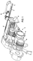
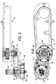
- the kicker assembly comprises a main housing 100 which is mounted on the rod maker.
- a drive 110 which is driven from the rod maker drive via a shaft at the far end of the housing (not shown) through a timex pulley and belt (not shown).
- the drive transfers drive via a drive belt 112 to a kicker shaft 114.
- Both the drive shaft and the kicker shaft have toothed belt wheels 116 on which the drive belt is mounted.
- the belt 112 is retained inside a belt housing 118 to which is fixed a suction housing 120.
- the belt housing is pivotable about the drive 110 to set the kicker wheel at the correct height above the rod maker vee-rail. Attached to the belt housing is a bar 117 to which is fixed a guide plate 119.
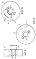
- the suction housing is shown in figures 8 to 10 and comprises a solid flange having a central aperture 122 and a hub 124 which is connected to the belt housing.
- a suction passage 126 is formed in the periphery of the flange at a position between the central axis of the flange and the front face.
- the suction passageway passes through the flange to a suction reservoir 128 at the rear of the flange.
- the reservoir 128 is provided to ensure a constant suction as will be described.
- the reservoir 128 is connected to a suction pump (not shown).
- This passageway 129 is a rod release passageway and is connected to an air supply (not shown) at the rear of the flange, the rod release passage way 129 passing through the flange approximately parallel to the suction passageway.
- the air supply pushes air through the rod release passage way to break the suction applied by the suction passageway to release rods from the kicker.
- a kicker wheel 130 Over the suction flange, which is static, is arranged a kicker wheel 130.
- the kicker wheel comprises a front face 132, a peripheral flange 134 and a hub 136.
- the hub passes through the central aperture 122 of the suction flange and is fixed to the kicker shaft 114 for rotation therewith.
- the peripheral flange is not continuous but divided into two sections of equal length by two relieved areas 138.
- Each flange section has a groove 140 running along its lengch with a series of equally spaced holes 142 formed at the base of the groove. In the figures the holes are shown as bing circular but they could equally well be elongate in the form of slots extending through the flange.
- the grooves are arranged off the centre of the flange such that they overlie the suction and rod release passageways of the suction flange, and such that when mounted on the housing, the grooves overlie the centreline 150 (fig 3) of tobacco rods on the vee-rail of the rod maker.
- the kicker wheel 130 rotates above the rods on the vee-rail.
- the suction provided through the holes in the grooves picks individual rods from the rail and the rotation of the kicker wheel accelerates the rods towards the receiving drum.
- the reservoir in the suction flange ensures that the suction is maintained.
- the suction is effectively being switched on and off as the holes pass over the suction aperture.
- the reservoir mitagates against a loss of suction which might cause a rod to be released from the kicker. This is particularly important with double length rods whose increased weight requires a greater suction.
- a rod will be released from the kicker when a relieved portion on the kicker periphery, where there are no holes or slots, passes over the suction passageway cutting off the suction and releasing the rods.
- the clearance between the flutes of the receiving drum 30 and its cover 40 is small and a raised tip could be damaged by the cover or, in the worst case, be prevented from entering the receiving drum causing the whole manufacturing line to break down.
- the air blown through the rod release passageway ensures that any residual suction is broken and chat the tip of the rod is exactly parallel with the receiving drum flutes when it is released. This ensures that the rod is successfully transferred from the vee-rail to the receiving drum.
- modified kicker described may be used with high speed double length rod makers enabling the advantages of low cost, simple kickers to be retained and obviating the need for complex, expensive transfer apparatus such as spiders.
- the kicker described is a straight, in-line kicker the invention is equally applicable to any other kicker such as a helical kicker which inserts a lateral component to the rod as it is being transformed.
Landscapes
- Manufacturing Of Cigar And Cigarette Tobacco (AREA)
- Nozzles For Electric Vacuum Cleaners (AREA)
- Hooks, Suction Cups, And Attachment By Adhesive Means (AREA)
Claims (12)
- Kicker-Baugruppe (20) zum Abnehmen von Tabakstöcken (12) von einer Tabakstockherstellungsvorrichtung und zum Beschleunigen dieser zu einer Tabakstockaufnahmestation (30), wobei die Baugruppe Folgendes umfasst:ein Sauggehäuse (120) mit einem Saugkanal (126), der sich von seiner Umfangswand erstreckt, und einem Tabakstockfreigabekanal (129), der sich von seinem Umfang erstreckt;ein Kicker-Rad (130) mit einem Flansch (134), der eine Mehrzahl von Löchern (142) hat, wobei das Kicker-Rad zur Drehung um das Sauggehäuse montiert ist, sodass die Löcher über den Saugkanal und den Tabakstockfreigabekanal passieren, wobei der Tabakstockfreigabekanal an den Saugkanal angrenzt und sich hinter dem Saugkanal befindet, sodass das Kicker-Rad zuerst mit durch den Saugkanal angelegter Saugkraft Tabakstöcke aufnimmt und dann die Tabakstöcke mittels durch den Tabakstockfreigabekanal angelegter Luft loslässt, undeinen Antrieb (110) zum Drehen des Kicker-Rads.
- Kicker-Baugruppe nach Anspruch 1, bei der der Flansch des Kicker-Rades zum Unterbrechen der Saugwirkung zum Tabakstock geformt ist, wenn Luft durch den Tabakstockfreigabekanal angelegt wird.
- Kicker-Baugruppe nach Anspruch 1 oder Anspruch 2, bei der das Sauggehäuse ferner einen Saugdruckbehälter aufweist, wobei sich der Saugkanal zwischen dem Saugdruckbehälter und der Umfangswand des Gehäuses erstreckt.
- Kicker-Baugruppe nach Anspruch 1, 2 oder 3, bei der der Saugkanal und der Tabakstockfreigabekanal parallel zueinander sind.
- Kicker-Baugruppe nach einem der vorangehenden Ansprüche, bei der sich die Löcher im Flansch des Kicker-Rades in der Nut im Flansch befinden.
- Kicker-Baugruppe nach Anspruch 5, bei der die Nut in einen ersten und einen zweiten Teil unterteilt ist, die durch ein Paar ausgesparter Flächen getrennt sind.
- Kicker-Baugruppe nach einem der vorangehenden Ansprüche, bei der der Saugkanal erlaubt, dass sich der Tabakstockfreigabekanal von Punkten am Umfang des Sauggehäuses zwischen der Mittelachse der Umfangswand und einem Rand der Umfangswand erstreckt.
- Kicker-Baugruppe nach einem der vorangehenden Ansprüche, bei der der Antrieb in einem Antriebsgehäuse montiert ist und das Funktionsgehäuse mit dem Antriebsgehäuse gekoppelt ist.
- Kicker-Baugruppe nach einem der vorangehenden Ansprüche, bei der das Kicker-Rad ein gerades Kicker-Rad ist, das Tabakstöcke in der Richtung des Tabakstockwegs entlang der Tabakstockherstellungseinheit weitgehend ohne laterale Komponente beschleunigt.
- Kicker-Baugruppe nach Anspruch 1 oder Anspruch 8, bei der das Kicker-Rad ein schraubenartiges Kicker-Rad ist, das Tabakstöcke in der Richtung des Tabakstockwegs entlang der Tabakstockherstellungseinheit mit einer lateralen Komponente beschleunigt.
- Kicker-Baugruppe (20) zum Abnehmen von Tabakstöcken (12) von einer Tabakstockherstellungsvorrichtung und zum Beschleunigen dieser zu einer Tabakstockaufnahmestation (30), wobei die Baugruppe Folgendes umfasst:ein Antriebsgehäuse (100) zur Anbringung an der Tabakstockherstellungsvorrichtung;eine in dem Gehäuse aufgenommene und wenigstens eine drehbare Welle aufweisende Antriebsvorrichtung (110);ein mit dem Gehäuse gekoppeltes Sauggehäuse (120), wobei das Sauggehäuse eine Umfangswand mit einer ersten Öffnung (126), die mit einer Saugvorrichtung verbunden ist, und einer zweiten Öffnung (129), die mit einer Luftzuleitung verbunden ist, hat; undein Kicker-Rad (130), das mit der Welle zur Drehung mit ihr verbunden ist, wobei das Kicker-Rad einen Umfangsflansch (134) hat, der um die Umfangswand des Sauggehäuses angeordnet ist zur Drehung um sie herum, und eine Mehrzahl von Löchern (142) hat, die positioniert sind, um beim Drehen über die ersten und zweiten Öffnungen des Sauggehäuses zu passieren, wobei jedes Loch erst über die erste Öffnung passiert, um Tabakstöcke von der Tabakstockherstellungsvorrichtung abzunehmen, und dann über die zweite Öffnung zum Freigeben von Tabakstöcken an die Tabakstockaufnahmestation.
- Kicker-Baugruppe nach einem der vorangehenden Ansprüche, bei der die Löcher im Flansch des Kicker-Rades Langlöcher sind.
Priority Applications (6)
| Application Number | Priority Date | Filing Date | Title |
|---|---|---|---|
| DE69810446T DE69810446T2 (de) | 1998-05-27 | 1998-05-27 | Vorrichtung zum Überführen von Stabförmigen artikeln |
| AT98304186T ATE230221T1 (de) | 1998-05-27 | 1998-05-27 | Vorrichtung zum überführen von stabförmigen artikeln |
| EP98304186A EP0960576B1 (de) | 1998-05-27 | 1998-05-27 | Vorrichtung zum Überführen von Stabförmigen artikeln |
| AU28473/99A AU2847399A (en) | 1998-05-27 | 1999-03-16 | Rod transfer apparatus |
| PCT/GB1999/000795 WO1999060873A1 (en) | 1998-05-27 | 1999-03-16 | Rod transfer apparatus |
| ARP990101967A AR015032A1 (es) | 1998-05-27 | 1999-04-28 | Un ensamble de lanzador para tomar y sacar las varitas fuera de un aparato que las confecciona |
Applications Claiming Priority (1)
| Application Number | Priority Date | Filing Date | Title |
|---|---|---|---|
| EP98304186A EP0960576B1 (de) | 1998-05-27 | 1998-05-27 | Vorrichtung zum Überführen von Stabförmigen artikeln |
Publications (2)
| Publication Number | Publication Date |
|---|---|
| EP0960576A1 EP0960576A1 (de) | 1999-12-01 |
| EP0960576B1 true EP0960576B1 (de) | 2003-01-02 |
Family
ID=8234851
Family Applications (1)
| Application Number | Title | Priority Date | Filing Date |
|---|---|---|---|
| EP98304186A Expired - Lifetime EP0960576B1 (de) | 1998-05-27 | 1998-05-27 | Vorrichtung zum Überführen von Stabförmigen artikeln |
Country Status (6)
| Country | Link |
|---|---|
| EP (1) | EP0960576B1 (de) |
| AR (1) | AR015032A1 (de) |
| AT (1) | ATE230221T1 (de) |
| AU (1) | AU2847399A (de) |
| DE (1) | DE69810446T2 (de) |
| WO (1) | WO1999060873A1 (de) |
Families Citing this family (1)
| Publication number | Priority date | Publication date | Assignee | Title |
|---|---|---|---|---|
| DE102006060979B4 (de) | 2006-12-20 | 2015-06-18 | Hauni Maschinenbau Ag | Förderstabilisator |
Family Cites Families (4)
| Publication number | Priority date | Publication date | Assignee | Title |
|---|---|---|---|---|
| NL248221A (de) * | 1959-02-10 | |||
| DE3423570A1 (de) * | 1983-07-13 | 1985-01-24 | Hauni-Werke Körber & Co KG, 2050 Hamburg | Vorrichtung zum ueberfuehren von stabfoermigen artikeln der tabakverarbeitenden industrie aus einer laengsaxialen in eine queraxiale foerderrichtung |
| GB8324510D0 (en) * | 1983-09-13 | 1983-10-12 | Molins Plc | Cigarette making machine |
| DE3603895C1 (en) * | 1986-02-05 | 1987-06-25 | Bat Cigarettenfab Gmbh | Accelerator on a machine in the tobacco processing industry |
-
1998
- 1998-05-27 DE DE69810446T patent/DE69810446T2/de not_active Expired - Fee Related
- 1998-05-27 EP EP98304186A patent/EP0960576B1/de not_active Expired - Lifetime
- 1998-05-27 AT AT98304186T patent/ATE230221T1/de not_active IP Right Cessation
-
1999
- 1999-03-16 WO PCT/GB1999/000795 patent/WO1999060873A1/en not_active Ceased
- 1999-03-16 AU AU28473/99A patent/AU2847399A/en not_active Abandoned
- 1999-04-28 AR ARP990101967A patent/AR015032A1/es not_active Application Discontinuation
Also Published As
| Publication number | Publication date |
|---|---|
| DE69810446D1 (de) | 2003-02-06 |
| DE69810446T2 (de) | 2003-10-02 |
| WO1999060873A1 (en) | 1999-12-02 |
| EP0960576A1 (de) | 1999-12-01 |
| AU2847399A (en) | 1999-12-13 |
| AR015032A1 (es) | 2001-04-11 |
| ATE230221T1 (de) | 2003-01-15 |
Similar Documents
| Publication | Publication Date | Title |
|---|---|---|
| KR101504386B1 (ko) | 멀티 세그멘트 필터를 생산하는 공정에서 세그멘트 그룹을 수집하는 방법 및 멀티 세그멘트 필터를 생산하는 공정에서 세그멘트를 그룹으로 준비하고 수집하기 위한 장치 | |
| US6736257B2 (en) | Device and method for transferring articles in the tobacco-processing industry | |
| US2988198A (en) | Cigarette turn around device | |
| US4867734A (en) | Apparatus for manufacturing dual filter plugs for cigarettes and method of manufacturing the same | |
| EP0960576A1 (de) | Vorrichtung zum Überführen von Stabförmigen artikeln | |
| US3854487A (en) | Manufacture of filter tipped cigarettes | |
| JPH08256750A (ja) | たばこ加工機械の分配機から過剰の作業空気を導出するための装置 | |
| CN101573053A (zh) | 具有贯穿其延伸的中空圆柱形管的烟丝条的生产方法 | |
| US4562916A (en) | Method and apparatus for transferring cigarettes from two makers into a filter tipping machine | |
| US3039590A (en) | Apparatus for receiving cigarettes or similar rod-like articles | |
| EP0966890B1 (de) | Übertragungsvorrichtung für Tabakstangen | |
| US3825105A (en) | Decelerator of cigarettes collected by a fluted drum | |
| US5908030A (en) | Device for transferring cigarette portions from a dual-rod cigarette manufacturing machine to a filter assembly machine | |
| GB2170693A (en) | Manufacture of cigarettes from two tobaccos | |
| JPH0656B2 (ja) | 巻煙草またはその他のロツド状物品を製造する機械 | |
| US6913023B2 (en) | Filter attaching apparatus | |
| JPS60118178A (ja) | たばこ流から過剰のたばこを取去るための装置 | |
| JP3126447B2 (ja) | 棒状物品の切断分離装置 | |
| JP3170222B2 (ja) | 葉もぎ装置 | |
| CN101287385B (zh) | 用于转移用来制造烟草制品的杆材料棒的单元 | |
| EP0350757B1 (de) | Maschine für die Herstellung von Filterzigaretten | |
| US4556072A (en) | Cigarette reversing apparatus | |
| US4305409A (en) | Cigarette making machines | |
| US12004556B2 (en) | Conveyor and method of aligning rod-shaped articles | |
| GB1133096A (en) | Improvements in or relating to methods and apparatus for feeding stubs pneumatically |
Legal Events
| Date | Code | Title | Description |
|---|---|---|---|
| PUAI | Public reference made under article 153(3) epc to a published international application that has entered the european phase |
Free format text: ORIGINAL CODE: 0009012 |
|
| AK | Designated contracting states |
Kind code of ref document: A1 Designated state(s): AT BE CH CY DE DK ES FI FR GB GR IE IT LI LU MC NL PT SE |
|
| AX | Request for extension of the european patent |
Free format text: AL;LT;LV;MK;RO;SI |
|
| 17P | Request for examination filed |
Effective date: 20000601 |
|
| AKX | Designation fees paid |
Free format text: AT BE CH CY DE DK ES FI FR GB GR IE IT LI LU MC NL PT SE |
|
| AXX | Extension fees paid |
Free format text: AL PAYMENT 20000601;LT PAYMENT 20000601;LV PAYMENT 20000601;MK PAYMENT 20000601;RO PAYMENT 20000601;SI PAYMENT 20000601 |
|
| GRAG | Despatch of communication of intention to grant |
Free format text: ORIGINAL CODE: EPIDOS AGRA |
|
| GRAG | Despatch of communication of intention to grant |
Free format text: ORIGINAL CODE: EPIDOS AGRA |
|
| 17Q | First examination report despatched |
Effective date: 20020211 |
|
| GRAG | Despatch of communication of intention to grant |
Free format text: ORIGINAL CODE: EPIDOS AGRA |
|
| GRAH | Despatch of communication of intention to grant a patent |
Free format text: ORIGINAL CODE: EPIDOS IGRA |
|
| GRAH | Despatch of communication of intention to grant a patent |
Free format text: ORIGINAL CODE: EPIDOS IGRA |
|
| GRAA | (expected) grant |
Free format text: ORIGINAL CODE: 0009210 |
|
| AK | Designated contracting states |
Kind code of ref document: B1 Designated state(s): AT BE CH CY DE DK ES FI FR GB GR IE IT LI LU MC NL PT SE |
|
| AX | Request for extension of the european patent |
Free format text: AL PAYMENT 20000601;LT PAYMENT 20000601;LV PAYMENT 20000601;MK PAYMENT 20000601;RO PAYMENT 20000601;SI PAYMENT 20000601 |
|
| PG25 | Lapsed in a contracting state [announced via postgrant information from national office to epo] |
Ref country code: NL Free format text: LAPSE BECAUSE OF FAILURE TO SUBMIT A TRANSLATION OF THE DESCRIPTION OR TO PAY THE FEE WITHIN THE PRESCRIBED TIME-LIMIT Effective date: 20030102 Ref country code: GR Free format text: LAPSE BECAUSE OF FAILURE TO SUBMIT A TRANSLATION OF THE DESCRIPTION OR TO PAY THE FEE WITHIN THE PRESCRIBED TIME-LIMIT Effective date: 20030102 Ref country code: FI Free format text: LAPSE BECAUSE OF FAILURE TO SUBMIT A TRANSLATION OF THE DESCRIPTION OR TO PAY THE FEE WITHIN THE PRESCRIBED TIME-LIMIT Effective date: 20030102 Ref country code: BE Free format text: LAPSE BECAUSE OF FAILURE TO SUBMIT A TRANSLATION OF THE DESCRIPTION OR TO PAY THE FEE WITHIN THE PRESCRIBED TIME-LIMIT Effective date: 20030102 Ref country code: AT Free format text: LAPSE BECAUSE OF FAILURE TO SUBMIT A TRANSLATION OF THE DESCRIPTION OR TO PAY THE FEE WITHIN THE PRESCRIBED TIME-LIMIT Effective date: 20030102 |
|
| REF | Corresponds to: |
Ref document number: 230221 Country of ref document: AT Date of ref document: 20030115 Kind code of ref document: T |
|
| REG | Reference to a national code |
Ref country code: GB Ref legal event code: FG4D Free format text: 20030102 |
|
| REG | Reference to a national code |
Ref country code: CH Ref legal event code: EP |
|
| REG | Reference to a national code |
Ref country code: IE Ref legal event code: FG4D |
|
| REF | Corresponds to: |
Ref document number: 69810446 Country of ref document: DE Date of ref document: 20030206 Kind code of ref document: P |
|
| REG | Reference to a national code |
Ref country code: CH Ref legal event code: NV Representative=s name: BOVARD AG PATENTANWAELTE |
|
| PG25 | Lapsed in a contracting state [announced via postgrant information from national office to epo] |
Ref country code: SE Free format text: LAPSE BECAUSE OF FAILURE TO SUBMIT A TRANSLATION OF THE DESCRIPTION OR TO PAY THE FEE WITHIN THE PRESCRIBED TIME-LIMIT Effective date: 20030402 Ref country code: PT Free format text: LAPSE BECAUSE OF FAILURE TO SUBMIT A TRANSLATION OF THE DESCRIPTION OR TO PAY THE FEE WITHIN THE PRESCRIBED TIME-LIMIT Effective date: 20030402 Ref country code: DK Free format text: LAPSE BECAUSE OF FAILURE TO SUBMIT A TRANSLATION OF THE DESCRIPTION OR TO PAY THE FEE WITHIN THE PRESCRIBED TIME-LIMIT Effective date: 20030402 |
|
| PG25 | Lapsed in a contracting state [announced via postgrant information from national office to epo] |
Ref country code: LU Free format text: LAPSE BECAUSE OF NON-PAYMENT OF DUE FEES Effective date: 20030527 Ref country code: IE Free format text: LAPSE BECAUSE OF NON-PAYMENT OF DUE FEES Effective date: 20030527 Ref country code: CY Free format text: LAPSE BECAUSE OF FAILURE TO SUBMIT A TRANSLATION OF THE DESCRIPTION OR TO PAY THE FEE WITHIN THE PRESCRIBED TIME-LIMIT Effective date: 20030527 |
|
| PG25 | Lapsed in a contracting state [announced via postgrant information from national office to epo] |
Ref country code: MC Free format text: LAPSE BECAUSE OF NON-PAYMENT OF DUE FEES Effective date: 20030531 |
|
| LTIE | Lt: invalidation of european patent or patent extension |
Effective date: 20030102 |
|
| PG25 | Lapsed in a contracting state [announced via postgrant information from national office to epo] |
Ref country code: ES Free format text: LAPSE BECAUSE OF FAILURE TO SUBMIT A TRANSLATION OF THE DESCRIPTION OR TO PAY THE FEE WITHIN THE PRESCRIBED TIME-LIMIT Effective date: 20030730 |
|
| ET | Fr: translation filed | ||
| PLBE | No opposition filed within time limit |
Free format text: ORIGINAL CODE: 0009261 |
|
| STAA | Information on the status of an ep patent application or granted ep patent |
Free format text: STATUS: NO OPPOSITION FILED WITHIN TIME LIMIT |
|
| 26N | No opposition filed |
Effective date: 20031003 |
|
| REG | Reference to a national code |
Ref country code: IE Ref legal event code: MM4A |
|
| PGFP | Annual fee paid to national office [announced via postgrant information from national office to epo] |
Ref country code: FR Payment date: 20040408 Year of fee payment: 7 |
|
| PGFP | Annual fee paid to national office [announced via postgrant information from national office to epo] |
Ref country code: CH Payment date: 20040413 Year of fee payment: 7 |
|
| PGFP | Annual fee paid to national office [announced via postgrant information from national office to epo] |
Ref country code: GB Payment date: 20040415 Year of fee payment: 7 |
|
| PGFP | Annual fee paid to national office [announced via postgrant information from national office to epo] |
Ref country code: DE Payment date: 20040422 Year of fee payment: 7 |
|
| PG25 | Lapsed in a contracting state [announced via postgrant information from national office to epo] |
Ref country code: IT Free format text: LAPSE BECAUSE OF NON-PAYMENT OF DUE FEES Effective date: 20050527 Ref country code: GB Free format text: LAPSE BECAUSE OF NON-PAYMENT OF DUE FEES Effective date: 20050527 |
|
| PG25 | Lapsed in a contracting state [announced via postgrant information from national office to epo] |
Ref country code: LI Free format text: LAPSE BECAUSE OF NON-PAYMENT OF DUE FEES Effective date: 20050531 Ref country code: CH Free format text: LAPSE BECAUSE OF NON-PAYMENT OF DUE FEES Effective date: 20050531 |
|
| PG25 | Lapsed in a contracting state [announced via postgrant information from national office to epo] |
Ref country code: DE Free format text: LAPSE BECAUSE OF NON-PAYMENT OF DUE FEES Effective date: 20051201 |
|
| REG | Reference to a national code |
Ref country code: CH Ref legal event code: PL |
|
| GBPC | Gb: european patent ceased through non-payment of renewal fee |
Effective date: 20050527 |
|
| PG25 | Lapsed in a contracting state [announced via postgrant information from national office to epo] |
Ref country code: FR Free format text: LAPSE BECAUSE OF NON-PAYMENT OF DUE FEES Effective date: 20060131 |
|
| REG | Reference to a national code |
Ref country code: FR Ref legal event code: ST Effective date: 20060131 |