EP0960591A2 - Tragfuss für eine Duschwanne - Google Patents
Tragfuss für eine Duschwanne Download PDFInfo
- Publication number
- EP0960591A2 EP0960591A2 EP99109003A EP99109003A EP0960591A2 EP 0960591 A2 EP0960591 A2 EP 0960591A2 EP 99109003 A EP99109003 A EP 99109003A EP 99109003 A EP99109003 A EP 99109003A EP 0960591 A2 EP0960591 A2 EP 0960591A2
- Authority
- EP
- European Patent Office
- Prior art keywords
- support
- foot according
- legs
- support foot
- support element
- Prior art date
- Legal status (The legal status is an assumption and is not a legal conclusion. Google has not performed a legal analysis and makes no representation as to the accuracy of the status listed.)
- Granted
Links
Images

Classifications
-
- A—HUMAN NECESSITIES
- A47—FURNITURE; DOMESTIC ARTICLES OR APPLIANCES; COFFEE MILLS; SPICE MILLS; SUCTION CLEANERS IN GENERAL
- A47K—SANITARY EQUIPMENT; ACCESSORIES THEREFOR, e.g. TOILET ACCESSORIES
- A47K3/00—Baths; Showers; Appurtenances therefor
- A47K3/16—Devices for fastening baths to floors or walls; Adjustable bath feet ; Lining panels or attachments therefor
- A47K3/17—Adjustable bath feet
Definitions
- the present invention relates to a support foot for a shower tray, in particular a support foot Support element and a height adjustable compared to this this fixable foot element, whose lower end on the The floor can rest, the support element supporting sections has the shower tray in their floor and / or Can support mirror area, and being the support element in the area of its support sections on the shower tray is attachable.
- feet are the aforementioned Kind usually with their support sections to the bottom the floor area or the mirror area of a shower tray glued. If the shower tray after gluing the support feet still has to be moved, there is a risk that the support feet by hitting an obstacle from the shower tray be knocked off. Furthermore, glued Do not remove the feet easily and on another Reinstall the spot, especially since the glue used may have a longer drying time. At shower trays with an acrylic core are occasionally out of the question Used to screw support feet to the shower trays. Such screwing turns out to be quite complex. Both screwing on and gluing the support feet have the disadvantage that the positions of the support feet are not specified, but usually tables and / or Assembly instructions must be taken. So it is not ensures that the support feet are in the optimal position to be assembled.
- the Support element comprises at least two bolt receptacles the bottom of the shower tray in the bottom and / or Mirror area attached bolts can take, the Bolt receptacles are so movable relative to each other that bolts received on them can be fixed on them.
- welding bolts provided, for example have a T shape.
- Such welding bolts are for example from German published application DE 195 02 705 A1 known, the one at the bottom of a tub fastened shaft-like part and a thickened, have a screw-like head that on the tub opposite end of the shaft-like part is arranged.
- Bolt seats which are preferably the shape of a one-sided have an open incision or a keyhole, in the bolts hooked so that the necks of the T-shaped, for example Bolts from the cuts or keyholes be included. Then the bolt receptacles so moved against each other that the bolts in them so to establish a secure connection between Support foot and underside of the shower tray are created.
- a support foot using a Retaining tab hung on a weld-on bolt. Only by Bracing two support feet against each other can on the Bottom of a tub. In contrast offers the support foot according to the invention the advantage that it as independent unit by moving its bolt receptacles For example, two bolts assigned to it can be set can.
- the support element can preferably have two legs include, which are pivoted relative to each other and can be braced against each other, each of the Leg has at least one bolt seat through Swiveling the legs are movable relative to each other.
- the necks of those recorded in the bolt receptacles T-bolts are pressed to the ends of the incisions so that they are kept safe in these.
- the support element as a one-piece sheet metal part executed, preferably the support portions of the Support element by upper bends of the two legs are formed inside.
- the support foot can advantageously comprise tensioning means, through which the legs towards each other or away from each other can be pivoted, according to one embodiment the present invention the clamping means one both Threaded rod or screw connecting the legs and includes nuts that can be screwed onto them.
- the nuts may be a hex nut or the head of the screw can be used as a hexagon be formed in a on one of the legs trained hexagon embossing can be held, whereas the second nut can be designed as a wing nut, by tightening the two legs towards each other or be pivoted away from each other.
- Hexagon embossing can also have a similar for example in the form of punched-out edges Find.
- a clamping device can also be used on the Support element slidable profile part of preferably U-shaped Serve cross-section, by sliding the Legs can be pivoted towards each other, which makes the Neck the T-bolt into the ends of the incisions of the Bolt receptacles are pressed.
- pads on the tops of the support sections attachable from a soft material, which is preferably attached their side facing the support section
- the upholstery lies on the Bottom of the shower tray in the floor area or in Mirror area and cause on the one hand Protect sound decoupling between shower tray and floor secondly, the underside of the shower base from damage.
- the support element advantageously has on it Underside an internal thread, the foot element one in this in and out of this screw rod or screw.
- a plastic cap Preferably at the bottom of the Threaded rod or screw rotatably a plastic cap to be appropriate.
- Threaded rod or screw By screwing in and out Threaded rod or screw can adjust the height of the support foot to be changed.
- the threaded rod or Screw preferably over its entire length with a Thread provided so that the height adjustability of the Support foot is optimized.
- the Plastic cap formed in a star shape so that it without Tool easily gripped and twisted for height adjustment can be.
- the plastic cap can be rounded, so that it can also be moved on rough or uneven surfaces and provides the support foot with a firm footing.
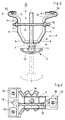
- Fig. 2 includes an inventive Support foot a support element 1, from which a foot element 2 after can be unscrewed at the bottom. This is through the dash-dotted position of the screwed down Foot element 2 illustrated in Fig. 2.
- the support element 1 which is shown in perspective in FIG. 1 is preferably in one piece from a sheet metal strip formed by bending and punching. Its side edges point a side bend 3 on the stability of the Support element increased. In the side view it is Support element 1 is approximately V-shaped or U-shaped, wherein the top two ends of the V or U legs first outside and above inwardly bent support sections 4 form. At the support sections 4 close down approximately parallel clamping sections 5, whose function is described in more detail below. The clamping sections 5 close conically at the bottom inside tapered sections 6 into a lower horizontal section 7 pass over the two conical Sections 6 connects together.
- Fig. 1 can be seen that the left leg in Fig. 2 of the support element 1 is horizontal from the lower extending section 7 up to the support section 4 widened, whereas the right leg of the Support element 1 approximately the same over its entire height Width as the lower horizontal section 7 having.
- the lower horizontal section 7 has an internal thread 8 arranged somewhat outside its center.
- the foot element comprises 2 a threaded rod 9, which into the internal thread 8 or can be screwed out of the internal thread 8.
- the Threaded rod 9 is up to its upper end with a Provide threads to adjust the depth of adjustment as much as possible guarantee.
- On the lower end of the threaded rod 9 is rotatably applied a plastic cap 10.
- the Plastic cap 10 is shaped in a star shape to rotate the to facilitate connected threaded rod 9 (see Fig. 3).
- the threaded rod 9 Screw can be used.
- the right leg of the support element 1 in FIG its clamping section 5 a little off center Hexagon embossing 12, in the middle a continuous Bore 13 is added.
- the hexagon embossing 12 can also have another rotation hindrance, for example in the form of punched-out edges can be used.
- the Clamping section 5 of the opposite in Fig. 2 left Leg also has eccentric, the bore 13 opposite a corresponding bore 14 on the together with the bore 13 for receiving a threaded rod 15 serves.
- 14th threaded rod 15 pushed through is on the in Fig. 2nd left end a wing nut 16 and on the right in Fig. 2 Screwed on a hexagon screw 17 at the end.
- the Hexagon screw 17 is in hexagon embossing 12 added and does not have to when tightening the wing nut 16 be held.
- Threaded rod 15 instead of Threaded rod 15 used a screw whose head is provided with a hexagon, for example.
- the support sections 4 of the two legs of the support element 1 each have an inward cut open bolt receptacle 18.
- two bores 19 and in the support section shown on the right in FIG. 2 Bore 20 provided for receiving latching elements 21st serve with an undercut, the upholstery 22 wear that have an approximately rectangular outline and are slightly arched (see Fig. 3).
- the upholstery 22 can their top at the bottom of the bottom area or the Mirror area of a shower tray and so for one Provide sound decoupling and the shower tray Protect damage.
- a shower tray T-shaped Bolts attached in which serve as the receiving means Bolt receptacles 18 are hooked so that the neck of the T-shaped Bolts from those opened inwards incision-shaped pin receptacles 18 is added.
- Bolt receptacles 18 are hooked so that the neck of the T-shaped Bolts from those opened inwards incision-shaped pin receptacles 18 is added.
- the wing nut 16 dressed.
- the two legs of the Support element 1 moves towards each other, causing the necks of the T-shaped bolt firmly against the outer ends of the incision-shaped pin receptacles 18 are pressed.
- the support foot according to the invention on the underside of the shower tray attached.
- incised bolt receptacles open on the outside, which is also behind at the bottom of the shower tray attached T-bolts can be hooked.
- suitable thread means or suitable Plug-in profile blocks the legs of the support element 1 apart. This can be done, for example happen that the wing nut and the hex nut press the inside of the thighs and tighten them move apart.
Landscapes
- Health & Medical Sciences (AREA)
- Public Health (AREA)
- Epidemiology (AREA)
- General Health & Medical Sciences (AREA)
- Bathtubs, Showers, And Their Attachments (AREA)
- Domestic Plumbing Installations (AREA)
- Devices For Medical Bathing And Washing (AREA)
- Massaging Devices (AREA)
Abstract
Description
- Fig. 1
- eine perspektivische Ansicht eines Stützelements eines erfindungsgemäßen Tragfusses;
- Fig. 2
- einen Querschnitt durch einen erfindungsgemäßen Tragfuß;
- Fig. 3
- eine Ansicht gemäß dem Pfeil III in Fig. 2.
Claims (15)
- Tragfuß für eine Duschwanne umfassend ein Stützelement (1) und ein gegenüber diesem höhenverstellbares, an diesem festlegbares Fußelement (2) , dessen unteres Ende auf dem Boden ruhen kann, wobei das Stützelement (1) Stützabschnitte (4) aufweist, die die Duschwanne in ihrem Boden- und/oder Spiegelbereich abstützen können, und wobei das Stützelement (1) im Bereich seiner Stützabschnitte (4) an der Duschwanne befestigbar ist, dadurch gekennzeichnet, daß das Stützelement (1) mindestens zwei Bolzenaufnahmen (18) umfaßt, die an der Unterseite der Duschwanne in deren Boden- und/oder Spiegelbereich angebrachte Bolzen aufnehmen können, wobei die Bolzenaufnahmen (18) so relativ zueinander bewegbar sind, daß von ihnen aufgenommene Bolzen an ihnen festgelegt werden können.
- Tragfuß nach Anspruch 1, dadurch gekennzeichnet, daß das Stützelement (1) zwei Schenkel umfaßt, die relativ zueinander verschwenkt und gegeneinander verspannt werden können, wobei jeder der Schenkel mindestens eine Bolzenaufnahme (18) aufweist, die durch Verschwenken der Schenkel relativ zueinander bewegbar sind.
- Tragfuß nach Anspruch 2, dadurch gekennzeichnet, daß die Bolzen an der Unterseite der Duschwanne eine T-Form aufweisen und die Bolzenaufnahmen (18) als Schlüsselloch oder einseitig offen in Form eines Einschnitts ausgebildet sind, das oder der den Hals eines T-förmigen Bolzens aufnehmen kann.
- Tragfuß nach Anspruch 3, dadurch gekennzeichnet, daß durch verschwenken der Schenkel des Stützelements (1) relativ zueinander die Hälse von in den Bolzenaufnahmen (18) aufgenommenen T-Bolzen an die Enden der Einschnitte gepreßt werden.
- Tragfuß nach einem der Ansprüche 1 bis 4, dadurch gekennzeichnet, daß das Stützelement (1) als einstückiges Blechteil ausgeführt ist.
- Tragfuß nach einem der Ansprüche 2 bis 5, dadurch gekennzeichnet, daß die Stützabschnitte (4) des Stützelements (1) durch obere Umbiegungen der Schenkel nach innen gebildet sind.
- Tragfuß nach einem der Ansprüche 2 bis 6, dadurch gekennzeichnet, daß der Tragfuß weiterhin Spannmittel (12, 13, 14, 15, 16, 17) umfaßt, durch die die Schenkel des Stützelements (1) aufeinander zu oder voneinander weg geschwenkt werden können.
- Tragfuß nach Anspruch 7, dadurch gekennzeichnet, daß die Spannmittel eine die beiden Schenkel miteinander verbindende Gewindestange (15) oder Schraube und auf diese ausschraubbare Muttern (16, 17) umfaßt.
- Tragfuß nach Anspruch 8, dadurch gekennzeichnet, daß eine der Muttern eine Flügelmutter (18) ist und eine der Muttern eine Sechskantmutter (17) ist, die in einer an einem der Schenkel ausgebildeten Drehbehinderung, die beispielsweise als Sechskantprägung (12) oder als herausgestanzte Kanten ausgeführt ist, gehalten werden kann.
- Tragfuß nach Anspruch 7, dadurch gekennzeichnet, daß die Spannmittel ein auf das Stützelement aufschiebbares Profilteil, vorzugsweise mit U-förmigen Querschnitt, umfassen, durch dessen Aufschieben die Schenkel aufeinander zu geschwenkt werden können.
- Tragfuß nach einem der Ansprüche 1 bis 10, dadurch gekennzeichnet, daß auf der Oberseite der Stützabschnitte (4) Polster (22) aus einem weichen Material anbringbar sind, die vorzugsweise an ihrer dem Stützabschnitt (4) zugewandten Seite jeweils ein Rastelement (21) mit Hinterschnitt aufweisen, das in Bohrungen (19, 20) in dem Stützabschnitt (4) einrastbar ist.
- Tragfuß nach einem der Ansprüche 1 bis 11, dadurch gekennzeichnet, daß das Stützelement (1) an seiner Unterseite ein Innengewinde (8) aufweist und daß das Fußelement (2) eine in dieses hinein und aus diesem herausschraubbare Gewindestange (9) oder Schraube umfaßt.
- Tragfuß nach Anspruch 12, dadurch gekennzeichnet, daß am unteren Ende der Gewindestange (9) oder Schraube drehfest eine Kunststoffkappe (10) angebracht ist.
- Tragfuß nach Anspruch 13, dadurch gekennzeichnet, daß die Kunststoffkappe (10) sternförmig ausgebildet ist.
- Tragfuß nach einem der Ansprüche 12 bis 14, dadurch gekennzeichnet, daß das Stützelement (1) im wesentlichen V-förmig oder U-förmig gestaltet ist, wobei die beiden Schenkel bodenseitig über einen waagerecht verlaufenden Abschnitt (7) miteinander verbunden sind, in dem das Innengewinde (8) ausgebildet ist.
Applications Claiming Priority (2)
| Application Number | Priority Date | Filing Date | Title |
|---|---|---|---|
| DE19823403A DE19823403C2 (de) | 1998-05-26 | 1998-05-26 | Tragfuß für eine Duschwanne |
| DE19823403 | 1998-05-26 |
Publications (3)
| Publication Number | Publication Date |
|---|---|
| EP0960591A2 true EP0960591A2 (de) | 1999-12-01 |
| EP0960591A3 EP0960591A3 (de) | 2000-09-13 |
| EP0960591B1 EP0960591B1 (de) | 2003-07-16 |
Family
ID=7868916
Family Applications (1)
| Application Number | Title | Priority Date | Filing Date |
|---|---|---|---|
| EP99109003A Expired - Lifetime EP0960591B1 (de) | 1998-05-26 | 1999-05-06 | Tragfuss für eine Duschwanne |
Country Status (3)
| Country | Link |
|---|---|
| EP (1) | EP0960591B1 (de) |
| AT (1) | ATE245001T1 (de) |
| DE (2) | DE19823403C2 (de) |
Families Citing this family (1)
| Publication number | Priority date | Publication date | Assignee | Title |
|---|---|---|---|---|
| DE102008012508B4 (de) | 2008-03-04 | 2019-05-16 | Mepa-Pauli Und Menden Gmbh | Höhenverstellbarer Tragfuß für eine Wanne, sowie ein Traggestell |
Citations (1)
| Publication number | Priority date | Publication date | Assignee | Title |
|---|---|---|---|---|
| DE19502705A1 (de) | 1994-04-27 | 1995-11-02 | Kaldewei Franz Gmbh & Co | Traggestell für eine Badewanne oder Duschwanne |
Family Cites Families (3)
| Publication number | Priority date | Publication date | Assignee | Title |
|---|---|---|---|---|
| GB350686A (en) * | 1930-05-16 | 1931-06-18 | George Mochrie Logan | Improvements in or relating to baths |
| AT169144B (de) * | 1950-08-17 | 1951-10-10 | Austria Email Ag | Fußbefestigung für Badewannen od. dgl. |
| DE29717613U1 (de) * | 1997-10-02 | 1997-11-20 | Franz Kaldewei GmbH & Co, 59229 Ahlen | Traggestell für eine Badewanne oder Duschwanne |
-
1998
- 1998-05-26 DE DE19823403A patent/DE19823403C2/de not_active Expired - Fee Related
-
1999
- 1999-05-06 DE DE59906281T patent/DE59906281D1/de not_active Expired - Fee Related
- 1999-05-06 EP EP99109003A patent/EP0960591B1/de not_active Expired - Lifetime
- 1999-05-06 AT AT99109003T patent/ATE245001T1/de not_active IP Right Cessation
Patent Citations (1)
| Publication number | Priority date | Publication date | Assignee | Title |
|---|---|---|---|---|
| DE19502705A1 (de) | 1994-04-27 | 1995-11-02 | Kaldewei Franz Gmbh & Co | Traggestell für eine Badewanne oder Duschwanne |
Also Published As
| Publication number | Publication date |
|---|---|
| EP0960591A3 (de) | 2000-09-13 |
| DE19823403C2 (de) | 2003-04-30 |
| ATE245001T1 (de) | 2003-08-15 |
| DE59906281D1 (de) | 2003-08-21 |
| DE19823403A1 (de) | 1999-12-09 |
| EP0960591B1 (de) | 2003-07-16 |
Similar Documents
| Publication | Publication Date | Title |
|---|---|---|
| DE102005018687B3 (de) | An einem Dacheindeckungselement angebrachte Halterung zur lösbaren Befestigung eines Gegenstandes, insbesondere eines Solarmoduls | |
| DE29507834U1 (de) | Reling-Befestigungsanordnung an Schubladen | |
| DE29808396U1 (de) | Regal | |
| DE4315603A1 (de) | Rohrgestell | |
| EP1338223B1 (de) | Einsteckvorrichtung, Einsteckteil sowie Anordnung zur Halterung von Gegenständen mit einer Einsteckvorrichtung und einem Einsteckteil | |
| EP0417177B1 (de) | Regalsystem | |
| EP0047961B1 (de) | Kugelkopfkupplung für Kraftfahrzeuge | |
| DE19823403C2 (de) | Tragfuß für eine Duschwanne | |
| DE29809994U1 (de) | Modular aufgebautes Tischgestell | |
| DE19502705C2 (de) | Traggestell für eine Badewanne oder Duschwanne | |
| EP0040180A1 (de) | Montagegestell | |
| DE102018203080B4 (de) | Fundamentsystem für die lagerung von flächig nebeneinander angeordneten solarpaneelen | |
| AT502463B1 (de) | Höhenverstellbare sitzvorrichtung | |
| DE934122C (de) | Tischfuss-Beschlag | |
| DE3611445C2 (de) | ||
| DE19917407C1 (de) | Schirmanschlußklemme | |
| DE19641065C1 (de) | Verstellbarer First- bzw. Gratlattenhalter | |
| EP3777615B1 (de) | Höheneinstellbares bett | |
| DE102006006403A1 (de) | Haltevorrichtung zum Halten eines Einbaugerätes an einer Arbeitsplatte | |
| EP2784019A1 (de) | Vorrichtung zur unterseitigen Abstützung eines Kfz-Motors | |
| CH695905A5 (de) | Abstand- und Distanzhalter. | |
| DE29608455U1 (de) | Befestigungsvorrichtung, nämlich für Bretter, Regalbretter o.dgl. | |
| DE29919446U1 (de) | Haltevorrichtung für eine Deckenrandschalung | |
| DE9308536U1 (de) | Halterung für die Befestigung von Balkonbegrenzungsplatten u.ä. | |
| DE10019216A1 (de) | Dachträgervorrichtung an Motorfahrzeugen |
Legal Events
| Date | Code | Title | Description |
|---|---|---|---|
| PUAI | Public reference made under article 153(3) epc to a published international application that has entered the european phase |
Free format text: ORIGINAL CODE: 0009012 |
|
| AK | Designated contracting states |
Kind code of ref document: A2 Designated state(s): AT BE CH DE ES FR GB LI LU NL |
|
| AX | Request for extension of the european patent |
Free format text: AL;LT;LV;MK;RO;SI |
|
| PUAL | Search report despatched |
Free format text: ORIGINAL CODE: 0009013 |
|
| AK | Designated contracting states |
Kind code of ref document: A3 Designated state(s): AT BE CH CY DE DK ES FI FR GB GR IE IT LI LU MC NL PT SE |
|
| AX | Request for extension of the european patent |
Free format text: AL;LT;LV;MK;RO;SI |
|
| RIC1 | Information provided on ipc code assigned before grant |
Free format text: 7A 47K 3/22 A, 7A 47K 3/17 B |
|
| 17P | Request for examination filed |
Effective date: 20000826 |
|
| AKX | Designation fees paid |
Free format text: AT BE CH DE ES FR GB LI LU NL |
|
| RAP1 | Party data changed (applicant data changed or rights of an application transferred) |
Owner name: FRANZ KALDEWEI GMBH & CO.KG |
|
| 17Q | First examination report despatched |
Effective date: 20020802 |
|
| GRAH | Despatch of communication of intention to grant a patent |
Free format text: ORIGINAL CODE: EPIDOS IGRA |
|
| RIC1 | Information provided on ipc code assigned before grant |
Free format text: 7A 47K 3/17 A |
|
| GRAH | Despatch of communication of intention to grant a patent |
Free format text: ORIGINAL CODE: EPIDOS IGRA |
|
| GRAA | (expected) grant |
Free format text: ORIGINAL CODE: 0009210 |
|
| AK | Designated contracting states |
Designated state(s): AT BE CH DE ES FR GB LI LU NL |
|
| PG25 | Lapsed in a contracting state [announced via postgrant information from national office to epo] |
Ref country code: NL Free format text: LAPSE BECAUSE OF FAILURE TO SUBMIT A TRANSLATION OF THE DESCRIPTION OR TO PAY THE FEE WITHIN THE PRESCRIBED TIME-LIMIT Effective date: 20030716 Ref country code: GB Free format text: LAPSE BECAUSE OF FAILURE TO SUBMIT A TRANSLATION OF THE DESCRIPTION OR TO PAY THE FEE WITHIN THE PRESCRIBED TIME-LIMIT Effective date: 20030716 Ref country code: FR Free format text: LAPSE BECAUSE OF FAILURE TO SUBMIT A TRANSLATION OF THE DESCRIPTION OR TO PAY THE FEE WITHIN THE PRESCRIBED TIME-LIMIT Effective date: 20030716 |
|
| REG | Reference to a national code |
Ref country code: GB Ref legal event code: FG4D Free format text: NOT ENGLISH |
|
| REG | Reference to a national code |
Ref country code: CH Ref legal event code: EP |
|
| REF | Corresponds to: |
Ref document number: 59906281 Country of ref document: DE Date of ref document: 20030821 Kind code of ref document: P |
|
| PG25 | Lapsed in a contracting state [announced via postgrant information from national office to epo] |
Ref country code: ES Free format text: LAPSE BECAUSE OF FAILURE TO SUBMIT A TRANSLATION OF THE DESCRIPTION OR TO PAY THE FEE WITHIN THE PRESCRIBED TIME-LIMIT Effective date: 20031027 |
|
| NLV1 | Nl: lapsed or annulled due to failure to fulfill the requirements of art. 29p and 29m of the patents act | ||
| GBV | Gb: ep patent (uk) treated as always having been void in accordance with gb section 77(7)/1977 [no translation filed] |
Effective date: 20030716 |
|
| PG25 | Lapsed in a contracting state [announced via postgrant information from national office to epo] |
Ref country code: LU Free format text: LAPSE BECAUSE OF NON-PAYMENT OF DUE FEES Effective date: 20040506 Ref country code: AT Free format text: LAPSE BECAUSE OF NON-PAYMENT OF DUE FEES Effective date: 20040506 |
|
| PLBE | No opposition filed within time limit |
Free format text: ORIGINAL CODE: 0009261 |
|
| STAA | Information on the status of an ep patent application or granted ep patent |
Free format text: STATUS: NO OPPOSITION FILED WITHIN TIME LIMIT |
|
| PG25 | Lapsed in a contracting state [announced via postgrant information from national office to epo] |
Ref country code: LI Free format text: LAPSE BECAUSE OF NON-PAYMENT OF DUE FEES Effective date: 20040531 Ref country code: CH Free format text: LAPSE BECAUSE OF NON-PAYMENT OF DUE FEES Effective date: 20040531 Ref country code: BE Free format text: LAPSE BECAUSE OF NON-PAYMENT OF DUE FEES Effective date: 20040531 |
|
| 26N | No opposition filed |
Effective date: 20040419 |
|
| EN | Fr: translation not filed | ||
| BERE | Be: lapsed |
Owner name: FRANZ *KALDEWEI G.M.B.H. & CO. K.G. Effective date: 20040531 |
|
| PG25 | Lapsed in a contracting state [announced via postgrant information from national office to epo] |
Ref country code: DE Free format text: LAPSE BECAUSE OF NON-PAYMENT OF DUE FEES Effective date: 20041201 |
|
| REG | Reference to a national code |
Ref country code: CH Ref legal event code: PL |