EP0960661A2 - Cage de laminoir - Google Patents
Cage de laminoir Download PDFInfo
- Publication number
- EP0960661A2 EP0960661A2 EP99303926A EP99303926A EP0960661A2 EP 0960661 A2 EP0960661 A2 EP 0960661A2 EP 99303926 A EP99303926 A EP 99303926A EP 99303926 A EP99303926 A EP 99303926A EP 0960661 A2 EP0960661 A2 EP 0960661A2
- Authority
- EP
- European Patent Office
- Prior art keywords
- roll
- bearing chocks
- work rolls
- nut members
- roll stand
- Prior art date
- Legal status (The legal status is an assumption and is not a legal conclusion. Google has not performed a legal analysis and makes no representation as to the accuracy of the status listed.)
- Withdrawn
Links
Images


Classifications
-
- B—PERFORMING OPERATIONS; TRANSPORTING
- B21—MECHANICAL METAL-WORKING WITHOUT ESSENTIALLY REMOVING MATERIAL; PUNCHING METAL
- B21B—ROLLING OF METAL
- B21B35/00—Drives for metal-rolling mills, e.g. hydraulic drives
- B21B35/14—Couplings, driving spindles, or spindle carriers specially adapted for, or specially arranged in, metal-rolling mills
-
- B—PERFORMING OPERATIONS; TRANSPORTING
- B21—MECHANICAL METAL-WORKING WITHOUT ESSENTIALLY REMOVING MATERIAL; PUNCHING METAL
- B21B—ROLLING OF METAL
- B21B31/00—Rolling stand structures; Mounting, adjusting, or interchanging rolls, roll mountings, or stand frames
- B21B31/02—Rolling stand frames or housings; Roll mountings ; Roll chocks
- B21B31/04—Rolling stand frames or housings; Roll mountings ; Roll chocks with tie rods in frameless stands, e.g. prestressed tie rods
-
- B—PERFORMING OPERATIONS; TRANSPORTING
- B21—MECHANICAL METAL-WORKING WITHOUT ESSENTIALLY REMOVING MATERIAL; PUNCHING METAL
- B21B—ROLLING OF METAL
- B21B31/00—Rolling stand structures; Mounting, adjusting, or interchanging rolls, roll mountings, or stand frames
-
- B—PERFORMING OPERATIONS; TRANSPORTING
- B21—MECHANICAL METAL-WORKING WITHOUT ESSENTIALLY REMOVING MATERIAL; PUNCHING METAL
- B21B—ROLLING OF METAL
- B21B31/00—Rolling stand structures; Mounting, adjusting, or interchanging rolls, roll mountings, or stand frames
- B21B31/08—Interchanging rolls, roll mountings, or stand frames, e.g. using C-hooks; Replacing roll chocks on roll shafts
- B21B31/10—Interchanging rolls, roll mountings, or stand frames, e.g. using C-hooks; Replacing roll chocks on roll shafts by horizontally displacing, i.e. horizontal roll changing
Definitions
- This invention relates generally to rolling mills, and is concemed in particular with so-called “housingless” roll stands where the roll separating forces are absorbed by threaded spindles which extend between the bearing chocks of the work rolls.
- the work rolls are supported between bearing chocks for rotation about parallel axes.
- the bearing chocks include integral nuts which are threadedly engaged by opposite hand screw segments on spindles extending between adjacent bearing chocks of the respective work rolls.
- the spindles serve both to effect symmetrical roll parting adjustments, and to provide a short stress path loop for absorbing roll separating forces during rolling.
- spare roll package assemblies are maintained off line for quick interchangeability when the mill is down for maintenance. Because the nuts and adjusting spindles are integrally associated with their respective bearing chocks, a multiplicity of nuts and adjusting spindles are required to outfit not only the on line roll packages, but also the off line spares. This translates into a high and extremely burdensome capital investment.
- the nuts and associated adjusting spindles are totally divorced from the bearing chocks, thus enabling them to remain as permanent on line fixtures.
- the number of nuts and associated threaded spindles may thus be reduced to that required to service the active on line roll stands.
- the spare roll package assemblies remain free of these costly, components. resulting in a significant decrease in capital investment.
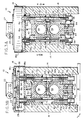
- a rolling mill roll stand in accordance with the present invention is generally depicted at 10.
- the roll stand includes a roll package 12 located on the mill pass line within a frame having four corner posts 14 which protrude vertically from a base 16 and are interconnected at their upper ends by a head structure 18.
- the head structure has a bottom 18a, side 18b and a top 18c defining an interior chamber 20.
- a worm gear reducer 22 is mounted on the head structure 18 exteriorly of the chamber 20.
- the gear reducer has a manually operable horizontal input shaft 24 and a vertically depending output shaft 25 carrying a drive gear 26.
- Gear 26 meshes with four driven gears 28 rotatably fixed to the upper ends of spindles 30 which depend through the bottom 18a of head structure 18.
- the spindles 30 extend downwardly through upper and lower nut members 32, 34. Opposite hand threaded segments 30a, 30b on the spindles 30 are in threaded engagement respectively with the upper and lower nut members 32, 34.
- the roll package 12 includes a pair of work rolls 36, 38 supported respectively for rotation about parallel axes by bearings (not shown) contained in bearing chocks 40, 42. Hydraulic separators 44 are interposed between the adjacent chocks 40, 42 of each work roll. The separators yieldably urge the chocks apart to thereby maintain a separation between the work rolls. As can best be seen in Figure 5, vertical links 46 are connected at opposite end to the chocks 40, 47. The links have slots 48 which accommodate the working range of roll parting adjustments.
- the nut members 32, 34 have inclined faces 50 arranged to engage oppositely inclined faces 52 on the respective chocks.
- the angle of inclinations of the faces 50, 52 with respect to the vertical is selected to generate resulting forces which pull the nut members against the chocks, and is preferably not greater than 75°.
- Tubular sleeves 54 on the upper nut members 32 cooperate with openings in the bottom 18a of head structure 18 to provide a guiding and locating function.
- Similar sleeves 56 depend from the lower nut members 42 to coact with stationary guides 58 forming part of the frame structure.
- the lower chocks 42 include depending keels 60 which carry support wheels 62. Tracks 64 underlie the wheels 62. During rolling and throughout the working range of roll parting as shown in Figure 3A, the nut members 32, 34 are closed symmetrically by rotation of the spindles 30 to engage the chocks 40, 47. The lower chock support wheels 62 are thus elevated above the underlying tracks 60. The inclined surfaces 50, 52 coact to firmly lock the nut members against the chocks.
- the spindles 30 are rotated to symmetrically separate the nut members 32, 34 to the open positions shown in Figure 3B. This results in the roll package being lowered with respect to the pass line P until the support wheels 62 come to rest on the tracks 64.
- the roll package may then be extracted laterally onto adjacent tracks 66, as shown by the broken lines in Figure 1.
- the spindles 30 and nut members 32, 34 remain with the frame on the pass line.
- a spare roll package may then be reinserted in the frame and brought into a rolling position by operating the spindles 30 to symmetrically return the nut members to their closed clamped positions as shown in Figure 3A.
Landscapes
- Engineering & Computer Science (AREA)
- Mechanical Engineering (AREA)
- Reduction Rolling/Reduction Stand/Operation Of Reduction Machine (AREA)
- Metal Rolling (AREA)
- Lining Or Joining Of Plastics Or The Like (AREA)
- Rolling Contact Bearings (AREA)
- Replacement Of Web Rolls (AREA)
Applications Claiming Priority (2)
| Application Number | Priority Date | Filing Date | Title |
|---|---|---|---|
| US85924 | 1987-08-17 | ||
| US09/085,924 US5983694A (en) | 1998-05-28 | 1998-05-28 | Rolling mill roll stand |
Publications (2)
| Publication Number | Publication Date |
|---|---|
| EP0960661A2 true EP0960661A2 (fr) | 1999-12-01 |
| EP0960661A3 EP0960661A3 (fr) | 2002-03-20 |
Family
ID=22194889
Family Applications (1)
| Application Number | Title | Priority Date | Filing Date |
|---|---|---|---|
| EP99303926A Withdrawn EP0960661A3 (fr) | 1998-05-28 | 1999-05-20 | Cage de laminoir |
Country Status (8)
| Country | Link |
|---|---|
| US (1) | US5983694A (fr) |
| EP (1) | EP0960661A3 (fr) |
| JP (1) | JP3217328B2 (fr) |
| KR (1) | KR19990088609A (fr) |
| BR (1) | BR9901677A (fr) |
| CA (1) | CA2271189A1 (fr) |
| RU (1) | RU2171152C2 (fr) |
| TW (1) | TW396064B (fr) |
Cited By (2)
| Publication number | Priority date | Publication date | Assignee | Title |
|---|---|---|---|---|
| WO2004080622A1 (fr) * | 2003-03-13 | 2004-09-23 | Sms Demag Ag | Cage de laminoir et procede pour regler une cage de laminoir |
| CN102133580B (zh) * | 2010-01-21 | 2012-05-30 | 无锡市瑞尔精密机械股份有限公司 | 轧辊机架用快速换辊装置和快速换辊方法 |
Families Citing this family (7)
| Publication number | Priority date | Publication date | Assignee | Title |
|---|---|---|---|---|
| US6164459A (en) * | 1999-01-21 | 2000-12-26 | Liem; Ken | Coin operated bicycle locking rack |
| GB9915870D0 (en) * | 1999-07-08 | 1999-09-08 | Meltog Ltd | Mandrel and tooling replacement and apparatus therefor |
| US6786144B2 (en) * | 2001-05-30 | 2004-09-07 | New Gencoat, Inc. | Wringer roller system |
| DE102004052395A1 (de) * | 2004-03-25 | 2005-10-13 | Sms Demag Ag | Einschubverfahren von Maschineneinheiten in eine Produktionslinie |
| JP6070947B2 (ja) * | 2013-09-11 | 2017-02-01 | Jfeスチール株式会社 | 圧延機の圧延ロール組替用レールの取り付け構造 |
| CN105251766B (zh) * | 2015-10-23 | 2017-06-27 | 徐州欧普莱斯工业机械有限公司 | 一种金属丝碾压装置 |
| CN105234182B (zh) * | 2015-11-27 | 2017-07-11 | 中冶南方工程技术有限公司 | 一种适用于十八辊冷轧机背衬系统的换辊组合装置 |
Family Cites Families (16)
| Publication number | Priority date | Publication date | Assignee | Title |
|---|---|---|---|---|
| GB1176132A (en) * | 1966-02-10 | 1970-01-01 | United Eng Foundry Co | Improvements in a Rolling Mill and Control for obtaining Constant Gauge |
| US3691809A (en) * | 1971-02-03 | 1972-09-19 | Mesta Machine Co | Mill roll changing arrangement |
| JPS5316791B2 (fr) * | 1974-02-18 | 1978-06-03 | ||
| IT1064628B (it) * | 1976-07-12 | 1985-02-25 | Innocenti Santeustacchio Spa | Gabbia perfezionata per presso laminatoio |
| GB1589299A (en) * | 1976-11-02 | 1981-05-13 | Loewy Robertson Eng Co Ltd | Rolling mill stand |
| DE2659763A1 (de) * | 1976-12-29 | 1978-07-13 | Mannesmann Ag | Rohrschweissmaschine mit wechselbaren walzen |
| US4279140A (en) * | 1979-10-17 | 1981-07-21 | United States Steel Corporation | Mill roll balance system |
| DE3008203A1 (de) * | 1980-03-04 | 1981-09-17 | Schloemann-Siemag AG, 4000 Düsseldorf | Stauchgeruest mit kraftbetrieben anstellbaren walzen |
| EP0103989A1 (fr) * | 1982-08-25 | 1984-03-28 | DAVY McKEE (SHEFFIELD) LIMITED | Laminoir à cage sans châssis |
| IT1174098B (it) * | 1984-05-28 | 1987-07-01 | Pomini Farrel Spa | Gabbia di laminazione del tipo a tiranti con supporti oscilanti con basi di appoggio intermedie |
| DE3436325A1 (de) * | 1984-10-04 | 1986-04-10 | SMS Schloemann-Siemag AG, 4000 Düsseldorf | Walzgeruest mit einem quer zur walzrichtung aus dem geruest heraus und in dieses einfahrbaren den walzensatz aufnehmenden fahrschlitten |
| DE3529364A1 (de) * | 1985-08-16 | 1987-02-19 | Schloemann Siemag Ag | Antriebsvorrichtung zur axialen verschiebung von walzen eines walzgeruestes |
| GB2197811B (en) * | 1986-11-11 | 1990-05-16 | Hille Eng Co Ltd | Rolling mill stand |
| ES2033996T3 (es) * | 1987-05-16 | 1993-04-01 | Sms Schloemann-Siemag Aktiengesellschaft | Caja de laminacion universal con juegos de cilindros horizontales y verticales aproximables. |
| DE4322389C2 (de) * | 1992-10-31 | 1996-09-05 | Thaelmann Schwermaschbau Veb | Ständerloses Walzgerüst |
| US5743126A (en) * | 1995-07-06 | 1998-04-28 | Morgan Construction Company | Roll stand with separable roll parting adjustment module |
-
1998
- 1998-05-28 US US09/085,924 patent/US5983694A/en not_active Expired - Lifetime
-
1999
- 1999-05-06 CA CA002271189A patent/CA2271189A1/fr not_active Abandoned
- 1999-05-20 EP EP99303926A patent/EP0960661A3/fr not_active Withdrawn
- 1999-05-24 JP JP14288599A patent/JP3217328B2/ja not_active Expired - Fee Related
- 1999-05-26 TW TW088107643A patent/TW396064B/zh active
- 1999-05-27 RU RU99112483/02A patent/RU2171152C2/ru not_active IP Right Cessation
- 1999-05-27 KR KR1019990019327A patent/KR19990088609A/ko not_active Ceased
- 1999-05-28 BR BR9901677-0A patent/BR9901677A/pt not_active Application Discontinuation
Cited By (2)
| Publication number | Priority date | Publication date | Assignee | Title |
|---|---|---|---|---|
| WO2004080622A1 (fr) * | 2003-03-13 | 2004-09-23 | Sms Demag Ag | Cage de laminoir et procede pour regler une cage de laminoir |
| CN102133580B (zh) * | 2010-01-21 | 2012-05-30 | 无锡市瑞尔精密机械股份有限公司 | 轧辊机架用快速换辊装置和快速换辊方法 |
Also Published As
| Publication number | Publication date |
|---|---|
| JP2000024708A (ja) | 2000-01-25 |
| KR19990088609A (ko) | 1999-12-27 |
| CA2271189A1 (fr) | 1999-11-28 |
| BR9901677A (pt) | 1999-12-14 |
| US5983694A (en) | 1999-11-16 |
| RU2171152C2 (ru) | 2001-07-27 |
| EP0960661A3 (fr) | 2002-03-20 |
| JP3217328B2 (ja) | 2001-10-09 |
| TW396064B (en) | 2000-07-01 |
Similar Documents
| Publication | Publication Date | Title |
|---|---|---|
| US5983694A (en) | Rolling mill roll stand | |
| KR101102907B1 (ko) | 롤을 교체하기 위한 방법 및 장치 | |
| CA1174086A (fr) | Laminoir compact | |
| CN1076144A (zh) | 万能轧机机座 | |
| US5596899A (en) | Mill housings for cluster mills | |
| GB2034222A (en) | Universal mill stand with removable rolls | |
| CN1107393A (zh) | 轴向移动式轧机 | |
| US3949586A (en) | Rolling mill frame, in particular a universal rolling mill frame | |
| AU707155B2 (en) | Roll replacing method and system for chockless rolling mill | |
| US4471642A (en) | Replacement stand for rolling mill | |
| EP0305466A1 (fr) | Structure de logement pour laminoir. | |
| CN1240682A (zh) | 滚轧机的轧机机座 | |
| US5622072A (en) | Levelling machine for levelling sheet metal and strip | |
| CN101128270A (zh) | 用于在线轧制特别是通过双辊带钢连铸制造的带钢的轧制装置 | |
| CA1163474A (fr) | Methode de laminage de rails | |
| EP0576930B1 (fr) | Procédé et dispositif pour la fabrication à chaud de barres rondes individuelles à partir d'éléments multiples chauds | |
| MXPA99004881A (en) | Shell cylinder box | |
| US4537056A (en) | Rolling mill | |
| US4287745A (en) | Rolling mill screwdown | |
| JPH0741289B2 (ja) | 圧延機 | |
| JP2787937B2 (ja) | 鋼板のアプセット装置 | |
| EP0052467A2 (fr) | Laminoir | |
| RU2134173C1 (ru) | Профилегибочная машина | |
| GB2070484A (en) | Rolling mill for bars or wire rods | |
| JPH06285529A (ja) | 条鋼圧延機の鋼片ガイド装置 |
Legal Events
| Date | Code | Title | Description |
|---|---|---|---|
| PUAI | Public reference made under article 153(3) epc to a published international application that has entered the european phase |
Free format text: ORIGINAL CODE: 0009012 |
|
| AK | Designated contracting states |
Kind code of ref document: A2 Designated state(s): AT BE CH CY DE DK ES FI FR GB GR IE IT LI LU MC NL PT SE Kind code of ref document: A2 Designated state(s): AT DE ES FR GB IT SE |
|
| AX | Request for extension of the european patent |
Free format text: AL;LT;LV;MK;RO;SI |
|
| PUAL | Search report despatched |
Free format text: ORIGINAL CODE: 0009013 |
|
| AK | Designated contracting states |
Kind code of ref document: A3 Designated state(s): AT BE CH CY DE DK ES FI FR GB GR IE IT LI LU MC NL PT SE |
|
| AX | Request for extension of the european patent |
Free format text: AL;LT;LV;MK;RO;SI |
|
| 17P | Request for examination filed |
Effective date: 20020223 |
|
| 17Q | First examination report despatched |
Effective date: 20021025 |
|
| AKX | Designation fees paid |
Free format text: AT DE ES FR GB IT SE |
|
| STAA | Information on the status of an ep patent application or granted ep patent |
Free format text: STATUS: THE APPLICATION IS DEEMED TO BE WITHDRAWN |
|
| 18D | Application deemed to be withdrawn |
Effective date: 20030506 |