EP0960682A2 - Procédé pour plaquer par soudage - Google Patents
Procédé pour plaquer par soudage Download PDFInfo
- Publication number
- EP0960682A2 EP0960682A2 EP99108923A EP99108923A EP0960682A2 EP 0960682 A2 EP0960682 A2 EP 0960682A2 EP 99108923 A EP99108923 A EP 99108923A EP 99108923 A EP99108923 A EP 99108923A EP 0960682 A2 EP0960682 A2 EP 0960682A2
- Authority
- EP
- European Patent Office
- Prior art keywords
- cladding
- foreign substance
- workpiece
- scheduled portion
- normal region
- Prior art date
- Legal status (The legal status is an assumption and is not a legal conclusion. Google has not performed a legal analysis and makes no representation as to the accuracy of the status listed.)
- Granted
Links
Images




Classifications
-
- B—PERFORMING OPERATIONS; TRANSPORTING
- B23—MACHINE TOOLS; METAL-WORKING NOT OTHERWISE PROVIDED FOR
- B23K—SOLDERING OR UNSOLDERING; WELDING; CLADDING OR PLATING BY SOLDERING OR WELDING; CUTTING BY APPLYING HEAT LOCALLY, e.g. FLAME CUTTING; WORKING BY LASER BEAM
- B23K26/00—Working by laser beam, e.g. welding, cutting or boring
- B23K26/08—Devices involving relative movement between laser beam and workpiece
- B23K26/0823—Devices involving rotation of the workpiece
-
- B—PERFORMING OPERATIONS; TRANSPORTING
- B08—CLEANING
- B08B—CLEANING IN GENERAL; PREVENTION OF FOULING IN GENERAL
- B08B7/00—Cleaning by methods not provided for in a single other subclass or a single group in this subclass
- B08B7/0035—Cleaning by methods not provided for in a single other subclass or a single group in this subclass by radiant energy, e.g. UV, laser, light beam or the like
- B08B7/0042—Cleaning by methods not provided for in a single other subclass or a single group in this subclass by radiant energy, e.g. UV, laser, light beam or the like by laser
-
- B—PERFORMING OPERATIONS; TRANSPORTING
- B23—MACHINE TOOLS; METAL-WORKING NOT OTHERWISE PROVIDED FOR
- B23K—SOLDERING OR UNSOLDERING; WELDING; CLADDING OR PLATING BY SOLDERING OR WELDING; CUTTING BY APPLYING HEAT LOCALLY, e.g. FLAME CUTTING; WORKING BY LASER BEAM
- B23K26/00—Working by laser beam, e.g. welding, cutting or boring
- B23K26/20—Bonding
- B23K26/32—Bonding taking account of the properties of the material involved
-
- B—PERFORMING OPERATIONS; TRANSPORTING
- B23—MACHINE TOOLS; METAL-WORKING NOT OTHERWISE PROVIDED FOR
- B23K—SOLDERING OR UNSOLDERING; WELDING; CLADDING OR PLATING BY SOLDERING OR WELDING; CUTTING BY APPLYING HEAT LOCALLY, e.g. FLAME CUTTING; WORKING BY LASER BEAM
- B23K26/00—Working by laser beam, e.g. welding, cutting or boring
- B23K26/34—Laser welding for purposes other than joining
-
- B—PERFORMING OPERATIONS; TRANSPORTING
- B23—MACHINE TOOLS; METAL-WORKING NOT OTHERWISE PROVIDED FOR
- B23K—SOLDERING OR UNSOLDERING; WELDING; CLADDING OR PLATING BY SOLDERING OR WELDING; CUTTING BY APPLYING HEAT LOCALLY, e.g. FLAME CUTTING; WORKING BY LASER BEAM
- B23K26/00—Working by laser beam, e.g. welding, cutting or boring
- B23K26/34—Laser welding for purposes other than joining
- B23K26/342—Build-up welding
-
- B—PERFORMING OPERATIONS; TRANSPORTING
- B23—MACHINE TOOLS; METAL-WORKING NOT OTHERWISE PROVIDED FOR
- B23K—SOLDERING OR UNSOLDERING; WELDING; CLADDING OR PLATING BY SOLDERING OR WELDING; CUTTING BY APPLYING HEAT LOCALLY, e.g. FLAME CUTTING; WORKING BY LASER BEAM
- B23K35/00—Rods, electrodes, materials, or media, for use in soldering, welding, or cutting
- B23K35/02—Rods, electrodes, materials, or media, for use in soldering, welding, or cutting characterised by mechanical features, e.g. shape
- B23K35/0222—Rods, electrodes, materials, or media, for use in soldering, welding, or cutting characterised by mechanical features, e.g. shape for use in soldering or brazing
- B23K35/0244—Powders, particles or spheres; Preforms made therefrom
-
- B—PERFORMING OPERATIONS; TRANSPORTING
- B23—MACHINE TOOLS; METAL-WORKING NOT OTHERWISE PROVIDED FOR
- B23K—SOLDERING OR UNSOLDERING; WELDING; CLADDING OR PLATING BY SOLDERING OR WELDING; CUTTING BY APPLYING HEAT LOCALLY, e.g. FLAME CUTTING; WORKING BY LASER BEAM
- B23K35/00—Rods, electrodes, materials, or media, for use in soldering, welding, or cutting
- B23K35/02—Rods, electrodes, materials, or media, for use in soldering, welding, or cutting characterised by mechanical features, e.g. shape
- B23K35/0255—Rods, electrodes, materials, or media, for use in soldering, welding, or cutting characterised by mechanical features, e.g. shape for use in welding
-
- B—PERFORMING OPERATIONS; TRANSPORTING
- B23—MACHINE TOOLS; METAL-WORKING NOT OTHERWISE PROVIDED FOR
- B23K—SOLDERING OR UNSOLDERING; WELDING; CLADDING OR PLATING BY SOLDERING OR WELDING; CUTTING BY APPLYING HEAT LOCALLY, e.g. FLAME CUTTING; WORKING BY LASER BEAM
- B23K35/00—Rods, electrodes, materials, or media, for use in soldering, welding, or cutting
- B23K35/22—Rods, electrodes, materials, or media, for use in soldering, welding, or cutting characterised by the composition or nature of the material
- B23K35/24—Selection of soldering or welding materials proper
- B23K35/30—Selection of soldering or welding materials proper with the principal constituent melting at less than 1550°C
- B23K35/302—Cu as the principal constituent
-
- B—PERFORMING OPERATIONS; TRANSPORTING
- B23—MACHINE TOOLS; METAL-WORKING NOT OTHERWISE PROVIDED FOR
- B23K—SOLDERING OR UNSOLDERING; WELDING; CLADDING OR PLATING BY SOLDERING OR WELDING; CUTTING BY APPLYING HEAT LOCALLY, e.g. FLAME CUTTING; WORKING BY LASER BEAM
- B23K2101/00—Articles made by soldering, welding or cutting
-
- B—PERFORMING OPERATIONS; TRANSPORTING
- B23—MACHINE TOOLS; METAL-WORKING NOT OTHERWISE PROVIDED FOR
- B23K—SOLDERING OR UNSOLDERING; WELDING; CLADDING OR PLATING BY SOLDERING OR WELDING; CUTTING BY APPLYING HEAT LOCALLY, e.g. FLAME CUTTING; WORKING BY LASER BEAM
- B23K2103/00—Materials to be soldered, welded or cut
- B23K2103/08—Non-ferrous metals or alloys
- B23K2103/10—Aluminium or alloys thereof
-
- B—PERFORMING OPERATIONS; TRANSPORTING
- B23—MACHINE TOOLS; METAL-WORKING NOT OTHERWISE PROVIDED FOR
- B23K—SOLDERING OR UNSOLDERING; WELDING; CLADDING OR PLATING BY SOLDERING OR WELDING; CUTTING BY APPLYING HEAT LOCALLY, e.g. FLAME CUTTING; WORKING BY LASER BEAM
- B23K2103/00—Materials to be soldered, welded or cut
- B23K2103/08—Non-ferrous metals or alloys
- B23K2103/12—Copper or alloys thereof
-
- B—PERFORMING OPERATIONS; TRANSPORTING
- B23—MACHINE TOOLS; METAL-WORKING NOT OTHERWISE PROVIDED FOR
- B23K—SOLDERING OR UNSOLDERING; WELDING; CLADDING OR PLATING BY SOLDERING OR WELDING; CUTTING BY APPLYING HEAT LOCALLY, e.g. FLAME CUTTING; WORKING BY LASER BEAM
- B23K2103/00—Materials to be soldered, welded or cut
- B23K2103/08—Non-ferrous metals or alloys
- B23K2103/14—Titanium or alloys thereof
-
- B—PERFORMING OPERATIONS; TRANSPORTING
- B23—MACHINE TOOLS; METAL-WORKING NOT OTHERWISE PROVIDED FOR
- B23K—SOLDERING OR UNSOLDERING; WELDING; CLADDING OR PLATING BY SOLDERING OR WELDING; CUTTING BY APPLYING HEAT LOCALLY, e.g. FLAME CUTTING; WORKING BY LASER BEAM
- B23K2103/00—Materials to be soldered, welded or cut
- B23K2103/18—Dissimilar materials
-
- B—PERFORMING OPERATIONS; TRANSPORTING
- B23—MACHINE TOOLS; METAL-WORKING NOT OTHERWISE PROVIDED FOR
- B23K—SOLDERING OR UNSOLDERING; WELDING; CLADDING OR PLATING BY SOLDERING OR WELDING; CUTTING BY APPLYING HEAT LOCALLY, e.g. FLAME CUTTING; WORKING BY LASER BEAM
- B23K2103/00—Materials to be soldered, welded or cut
- B23K2103/18—Dissimilar materials
- B23K2103/22—Ferrous alloys and copper or alloys thereof
-
- B—PERFORMING OPERATIONS; TRANSPORTING
- B23—MACHINE TOOLS; METAL-WORKING NOT OTHERWISE PROVIDED FOR
- B23K—SOLDERING OR UNSOLDERING; WELDING; CLADDING OR PLATING BY SOLDERING OR WELDING; CUTTING BY APPLYING HEAT LOCALLY, e.g. FLAME CUTTING; WORKING BY LASER BEAM
- B23K2103/00—Materials to be soldered, welded or cut
- B23K2103/50—Inorganic materials other than metals or composite materials
Definitions
- the present invention relates to a process of cladding by welding which is advantageous in suppressing defects of cladding.
- Japanese unexamined patent publication 6 (1994)-257,505 discloses a conventional process. Using a cylinder head formed of aluminum alloy having a cladding-scheduled portion for constituting a valve seat, this conventional process irradiates the cladding-scheduled portion with a laser beam to remelt and resolidify all of the surface of the cladding-scheduled portion. After that, this conventional process covers the resolidified portion with a clad layer. Even when the cladding-scheduled portion involves gas therein, this conventional process can release and eliminate gas so as to leave less gas in the cladding-scheduled portion before cladding. Accordingly, this conventional process can suppress expansion of gas in cladding the cladding-scheduled portion by welding.
- Japanese unexamined patent publication 64 (1989)-62,282 discloses another conventional process.
- This another conventional process forms a bead layer by high-frequency welding to produce a seam-welded ferrous pipe.
- This process irradiates the bead layer with a laser beam after immediately welding, so as to remelt and eliminate weld-defects remaining in the bead layer.
- the bead layer is irradiated with the laser beam in such a manner that the bead layer causes little or no molten metal.
- This process also discloses a technique which detects plasma light generated in eliminating the weld-defects so as to examine the presence of weld-defects in the bead layer.
- Japanese unexamined patent publication 6 (1994)-88,120 discloses still another conventional process concerning apparatuses which is to be employed in high temperatures, such as boilers or turbines. This process forms a bead layer by welding, and then irradiates a heat-affected zone in the vicinity of the welded bead layer with a laser beam or an electron beam so as to perform an eliminating step for eliminating the creep-voids remaining in the heat-affected zone.
- the present invention has been developed in view of the above circumstances.
- a process of the cladding by welding comprises the steps of: (1) preparing a workpiece having a cladding-scheduled portion including an exposed-normal region, the exposed normal region having a normal surface including a possibility that a foreign substance portion exists, and the foreign substance portion to form a defect in cladding; (2) irradiating the exposed normal region of the cladding-scheduled portion of the workpiece with a high-density energy beam, the high-density energy beam capable of eliminating or decreasing the foreign substance portion, substantially without melting the exposed normal region of the cladding-scheduled portion; and (3) covering the exposed normal region of the cladding-scheduled portion of the workpiece with a clad layer.
- the first aspect of the present invention eliminates the foreign substance portion existing in the cladding-scheduled portion of the workpiece, by irradiating the exposed normal region of the cladding-scheduled portion of the workpiece with the high-density energy beam. Thereafter, the first aspect of the present invention covers the cladding-scheduled portion of the workpiece with the clad layer. Therefore, when the cladding by welding is performed, the foreign substance portion in the cladding-scheduled portion is eliminated or decreased for purification. Accordingly, the first aspect of the present invention can suppress defects in cladding, thereby forming an appropriate clad layer to become advantageous in ensuring strength which the clad layer has originally.
- the first aspect of the present invention can suppress the melting of the exposed normal region having a normal surface which occupies the majority of the cladding-scheduled portion. Accordingly, the first aspect of the present invention can suppress roughness in the surface constituting the cladding-scheduled portion, thereby suppressing dispersion in thickness of the clad layer, as compared with the conventional technique which remelts all the surface of the exposed normal region and which is disclosed in the aforesaid unexamined patent publications.
- the first aspect of the present invention can suppress the transforming or the deteriorating of the exposed normal region of the cladding-scheduled portion, thereby advantageously ensuring balance of strength of the workpiece. Also, the first aspect of the present invention can prevent holes from being unexpectedly formed in the cladding-scheduled portion of the workpiece, even when the cladding-scheduled portion of the workpiece is restricted to be thin in thickness.
- the irradiating step generates a physical amount in eliminating or decreasing the foreign substance portion, and the irradiating step has a detecting operation for detecting a degree that the foreign substance portion is eliminated or decreased. So, the second aspect can detect the presence of the foreign substance portion, namely the remainder thereof, without destroying the workpiece.
- the second aspect of the present invention is advantageous in ensuring quality of the workpiece, provided that the information about the presence of the foreign substance portion is supplied with feed-back to production conditions for producing workpieces.
- the present invention uses a workpiece having a cladding scheduled-portion on which a clad layer is to be placed.
- the workpiece is not limited within material thereof; so, the workpiece may be formed of a well-known metal, such as aluminium family alloy, iron family alloy, or titanium family alloy.
- the aluminium family alloy may be casting alloy or expanding alloy.
- the alloy may include at least one element selected from a group consisting of Mg, Ni, and Fe, exemplyfing AC2A, AC4B, AC4D, AC5A, or AC1A in Japanese Industrial Standards (JIS).
- JIS Japanese Industrial Standards
- the workpiece may be material after heat-treatment.
- the heat-treatment may be one selected from a group from T2 treatment to T9 treatment ⁇ in particular T6 treatment.
- the workpiece may be cast products, forged products, and machined products.
- the high-density energy beam concerning the present invention is represented by a laser beam ⁇ sometimes an electron beam as occasion demands.
- the laser beam may be a CO 2 laser beam, a YAG laser beam, a Ruby laser beam, and the like.
- the high-density energy beam concerning the present invention has such a energy strength that a beam can eliminate or decrease the foreign substance portion existing in the cladding-scheduled portion, substantially without melting the exposed normal region of the cladding-scheduled portion.
- the workpiece has a larger reflection rate with respect to the high-density energy beam; the foreign substance portion has a higher absotptance rate than the workpiece with respect to the high-density energy beam. Accordingly, it is preferable that the present invention selects energy strength of the high-energy beam after consideration of a reflection rate and an absotptance rate with respect to the high-density energy beam.
- the foreign substance portion may be inclusions, such as non-metallic inclusions, which are generated or involved in the workpiece when the workpiece itself or material for constituting the workpiece is produced by pouring molten metal.
- inclusion is represented by oxides containing a base material component of the workpiece, or oxides containing other components.
- the lubricants, the detergents, or the water may enter the aforesaid concave defects as a foreign substance portion. Therefore, the foreign substance portion is represented by lubricants, detergents, or water which enter the aforesaid concave defects.
- the present preferable mode can melt or release the foreign substance portion, thereby eliminating or decreasing the foreign substance portion, or thereby sealing the foreign substance portion which is not exposed outwardly but remains. And then, the present preferable mode does not substantially melt the exposed normal region of the cladding-scheduled portion.
- the preferable mode covers the exposed normal region of the cladding-scheduled portion of the workpiece with a clad layer, after the eliminating step for eliminating or decreasing the foreign substance portion.
- the clad layer implies a layer with which the workpiece is overlaid.
- the clad layer can exhibit a welded bead layer, and a layer placed with flame-spray. Therefore, the cladding-scheduled portion is covered with the clad layer by a laser beam welding method.
- the preferable mode sometimes permits a usually-used arc welding method, a TIG arc welding method, or a MIG arc welding method.
- the present invention previously eliminates or decreases the foreign substance portion capable of forming defects in cladding. Accordingly, the present invention previously prevents defects in cladding from occurring in the clad layer. So, the present invention fundamentally differs from the conventional techniques which repair the defect after cladding.
- the repaired welded layer constituting the clad layer is good in appearance, it disadvantageously has discontinuity of its metallic structure, and a heat distortion because of local heat or local melting.
- a preferable mode of the present invention does not repair the clad layer after cladding, but pretreats the cladding-scheduled portion for elimination of the foreign substance portion before cladding. So, the preferable mode of the present invention can obtain an ability which the clad layer has originally.
- the preferable mode detects the physical amount so as to examine a degree that the foreign substance portion is eliminated or decreased, namely so as to examine the remainder of the foreign substance portion. Provided that information about elimination or decrease of the foreign substance portion is supplied with feed-back to a workpiece-producing method, the foreign substance portion can advantageously be reduced.
- the foreign substance portion When the physical amount is larger than a predetermined threshold value, the foreign substance portion may considerably be large, and a part of the foreign substance portion may remain. In this case, it is preferable that the workpiece is re-examined.
- the physical amount generated in eliminating the foreign substance portion is represented by a sound or light ⁇ an audible sound, visible light, a non-audible sound, and non-visible light.
- the present embodiment employs a workpiece 1 having the cladding-scheduled portion 10 exposed outwardly. All most of the cladding-scheduled portion 10 constitute an exposed normal region 10a having a normal surface 10c ⁇ the workpiece 1 has a high quality. So, very few parts of the cladding-scheduled portion 10 has a possibility that a foreign substance portion 2 exists.
- the foreign substance portion 2 is sometimes inclusions which are generated or involved in casting the workpiece 1 and which is exposed outwardly. Also, the foreign substance portion 2 is sometimes formed by detergents, lubricants, and water entered shrinkage holes, pin-holes, or seams generated at the cladding-scheduled portion 10 of the workpiece 1.
- the present embodiment eliminates the foreign substance portion 2 of the cladding-scheduled portion, before cladding by welding so as to improve quality of the workpiece 1 much further.
- the workpiece 1 is a cast product formed of aluminum alloy containing Cu and Si to exhibit a good castability.
- This aluminum alloy is JIS AC2C ⁇ cast products produced by use of a sand mold or by use of a metallic mold.
- the workpiece 1 is placed on a movable table 3 for moving two-dimensionally or three-dimensionally, an NC table.
- An eliminating step is performed.
- the movable table 3 is driven to move the workpiece 1.
- a laser beam 41 working as a high-density energy beam is discharged to the cladding-scheduled portion 10 of the workpiece 1 by way of a mirror 40c, from a laser-discharging apparatus 40, a CO 2 laser-discharging apparatus.
- the laser beam 41 has a wavelength of far infrared radiation, 10.6 ⁇ m.
- the laser beam 41 has an energy strength which eliminates the foreign substance portion 2 which is exposed at the cladding-scheduled portion 10 of the workpiece 1 and which does not substantially melt at the exposed normal region 10a of the cladding-scheduled portion 10 of the workpiece 1.
- a circumference of the foreign substance portion 2 may be remelted and resolidified to locally generate a remelted-resolidified portion 2c. Even when a part 2k of the foreign substance portion 2 remains, the remelted-resolidified portion 2c easily seals and covers such remaining part 2k, as shown in Fig. 2(C). Thus, it is prevented that a remaining part 2k is exposed outwardly.
- the remelted-resolidified portion 2c is only locally generated in the cladding-scheduled portion 10; so, the remelted-resolidified portion 2c is much smaller than the exposed normal region 10a in area.
- the present embodiment performs a covering step.
- a cladding material is piled onto the cladding-scheduled portion 10 to form a clad layer 15.
- the covering step allows that the covering material is irradiated with the laser beam, after or before the covering material is supplied onto the cladding-scheduled portion 10.
- the covering step may allow that a generally used welding method and a TIG welding method are employed in place of the laser beam.
- the foreign substance portion 2 may generate gas due to heat in cladding, thereby generating gaseous defects 15f such as pin-holes.
- the eliminating step concerning the present embodiment does not melt the exposed normal region 10a substantially. Therefore, the eliminating step is smaller than the covering step in input energy per unit time and unit area. Accordingly, in the eliminating step, "P1" exhibits output of the laser beam 41, “Q1” exhibits irradiation energy strength of the laser beam 41 per unit time and unit area, and “V1" exhibits a relative moving velocity between the workpiece 1 and the laser beam 41.
- the present embodiment satisfies at least one of the followings (1) -(3) P1 ⁇ P2 Q1 ⁇ Q2 V2>V1
- the laser beam 41 can easily reach a deep portion of the void-shaped defect. So, the laser beam 41 can eliminate the foreign substance potion 2 entering the deep portion of the void-shaped defect to generate the remelted-resolidified portion 2c.
- the remelted-resolidified portion 2c generally forms a deep shape having a key hole effect.
- a remelted-resolidified portion 2d is formed having a flat shape, as shown in Fig. 5 (B).
- the present embodiment is advantageous in making the clad layer 15 good and in ensuring strength of the clad layer 15.
- the present embodiment even when cladding-scheduled portion 10 of the workpiece 1 is irradiated with the laser beam 41, the laser beam 41 does not substantially melt the normal surface 10c of the exposed normal region 10a occupying the majority of the cladding-scheduled portion 10. So, the present embodiment suppresses roughness in the cladding-scheduled portion 10, and it prevents dispersion of the thickness in the clad layer 15, as distinct from the case where all surface of the cladding-scheduled portion 10 melts with subsequent resolidification. Accordingly, the present embodiment prevents the cladding-scheduled portion 10 from being transformed and deteriorated, and it prevents strength balance of the workpiece 1a from collapsing.
- Fig. 6 shows a graph exhibiting a relationship between a relative moving velocity and input heat which exhibits irradiation energy strength in the cladding-scheduled portion 10.
- the present inventor carried out a scanning system which oscillated a laser beam narrowed in diameter to realize an oscillation width of 6 [ mm ] ⁇ a focused oscillation system.
- the present inventor carried out another scanning system which enlarged a laser beam diameter with defocus to realize a beam diameter of 6 [ mm ] ⁇ a defocus system.
- the present inventor investigated about an adequate energy strength of the laser beam 41 for eliminating the foreign substance portion 2 exposed outwardly at the cladding-scheduled portion 10, without melting the exposed normal-region 10a of the cladding-scheduled portion 10.
- the present inventor carried out a scanning system which oscillated a laser beam narrowed in diameter to realize a oscillation width of 6 [ mm ] ⁇ a focused oscillation system.
- the present inventor carried out another scanning system which enlarged a laser beam diameter with defocus to realize a beam diameter of 6 [mm ] ⁇ a defocused system.
- the exceeding of 1 [ J /mm 2 ] effectively eliminated the majority of the foreign substance portion 2 being exposed at the cladding-scheduled portion 10, when the laser output exhibited 3 [kw].
- the unit of [ J ] is capable of being converted to a unit of [w ⁇ s].
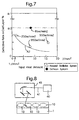
- Fig. 7 shows the investigated results with respect to a defective rate in the clad layer.
- Marks of " ⁇ " in Fig. 7 exhibit a scanning system which oscillates a focused laser beam 41 with an oscillation width of 6 [mm].
- Marks of " ⁇ ” in Fig. 7 exhibit a scanning system which uses a defocused laser beam 41 possessing an enlarged diameter having a beam width of 6 [mm].
- the defective rate of the clad layer indicated " ⁇ 1" in Fig. 7.
- the characteristic line "A2" in Fig. 7 indicated a considerable decrease in the defective rate, when input heat amount to the cladding-scheduled portion 10 was 1 [ J / mm 2 ] or more per unit time and area.
- the characteristic line "A2" in Fig. 7 when the input heat amount was larger, the defective rate was smaller in the clad layer.
- the excess of input heat amount improved an ability for eliminating the foreign substance portion2; however, it sometimes caused melting in the exposed normal region 10a of the cladding-scheduled portion 10. Thus, it is preferable that over-increase of input heat amount is avoided.
- Figs. 8 and 9 shows Example 1 which uses a workpiece 1 which is formed of aluminum alloy constituting a cylinder block of an engine.
- Example 1 performs a casting step for solidifying aluminum molten metal to obtain a cast product, a cleaning step for cleaning the cast product with a cleaning liquid including water and detergents, and a cutting step for cutting portions of the cast product with tools while lubricating the cast product.
- the workpiece 10 exhibits a high quality, having few impurities, few pin-holes, and a much smaller porosity rate.
- a eliminating step is performed with respect to the cladding-scheduled portion 10 before formation of the clad layer.
- Example 1 uses equipment including a laser-discharging apparatus 40 which is constituted by a CO 2 laser for discharging a laser beam 41, and which includes a beam-scanning apparatus 43.
- the bean-scanning apparatus 43 discharges the laser beam 41 from the laser-discharging apparatus 40 to all of cladding-scheduled portions 10.
- the conditions carried out by the present inventor were in Example 1 as follows:
- the cladding-scheduled portion 10 included a ring-shape having a width "D1" in a radius direction of approximately 10 [mm].
- the laser beam 41 was set at approximately 10 inches in focus distance, and the laser output was set at approximately 3 [kw].
- the beam-scanning apparatus 43 spirally discharged the laser beam 41 in such a manner that the laser beam 41 rotated 100 revolutions per second ⁇ 100 rps.
- the spiral diameter was set at 15 [mm] at an initial stage for an inner verge 10i of the cladding-scheduled portion 10, and it was set at 35 [mm] at a closing stage for an outer verge 10o of the cladding-scheduled portion 10.
- the sealing gas was unnecessary for preventing oxidation.
- the cladding-scheduled portion 10 was irradiated with the laser beam 41 as follows: firstly, as shown in Fig. 9 (A), the laser beam 41 spirally hit the inner verge 10i of the cladding-scheduled portion 10; secondarily, as shown in Fig. 9 (B), the laser beam 41 spirally hit a middle of the cladding-scheduled portion 10; continuously, as shown in Fig. 9 (C), the laser beam 41 spirally hit the outer verge 10o of the cladding-scheduled portion 10.
- Such spirally scanning operation shown in Figs. 9 (A) to 9 (C) was finished within one second.
- Example 1 performed a mode in which the laser beam 41 was spirally scanned from the inner verge 10i to the outer verge 10i. Conversely, Example 1 allows another mode in which the laser beam 41 is spirally scanned from the outer verge 10o to the inner verge 10i.
- Figs. 10 to 13 shows Example 2 which uses a workpiece 1 formed of aluminum alloy and constituting a cylinder head for a vehicle.
- Example 2 covers a plurality of ring-shaped valve seats with the clad layer.
- the valve seats constitute a cladding-scheduled portion 10, respectively.
- Example 2 For producing the workpiece 1, Example 2 performs a casting step for solidifying aluminum molten metal by a low-pressure casting method to obtain a cast product ( material: JIS AC2C ), a cleaning step for cleaning the cast product with a cleaning liquid including water and detergents, and a cutting step for cutting portions of the cast product with tools while lubricating the cast product with lubricants.
- a cast product material: JIS AC2C
- a cleaning step for cleaning the cast product with a cleaning liquid including water and detergents
- a cutting step for cutting portions of the cast product with tools while lubricating the cast product with lubricants.
- Example 2 the workpiece 10 is treated by T6 heat-treatment.
- the workpiece 10 exhibits a high quality, having few impurities, few pin-holes, and a much smaller porosity rate.
- Example 2 performs a eliminating step with respect to the valve seat constituting the cladding-scheduled portion 10 before formation of the clad layer.
- a base 50 concerning Example 2 includes a movable table 51 having a setting table 51c.
- the setting table 51c of the movable table 51 detachablely sets the workpiece 1.
- the setting table 51c is movable by Y-axial motor 53 in an arrow direction "Y", it is movable by X-axial motor 54 in an arrow direction "X, and it is rotatable by a ⁇ -axial motor 55 in an arrow direction " ⁇ " around a line which imaginarily connects a plurality of valve seats
- Example 2 the laser-discharging apparatus 40 constituted by a CO 2 laser discharges a laser beam 41 to the valve seats constituting the cladding-scheduled portion 10 in the cylinder head constituting the workpiece 1, by way of a lens 57 and a beam oscillator 58 shown in Fig. 12.
- the first detecting apparatus 71 and the second detecting 91 are disposed to approach the valve seat of the cylinder head.
- the first detecting apparatus 71 is to detect a degree to eliminate the foreign substance portion 2, on the basis of light constituting a physical amount, such as visible light, generated in eliminating the foreign substance portion 2.
- the first detecting apparatus 71 has a focusing lens 72, a light-receiving element 73 for receiving light passed through the focusing lens 72 and for transmitting receive electric signals, an amplifier circuit 74 for amplifying the receive electric signals, a correcting circuit 75 for correcting a distortion of the receive electric signals, a filter circuit 76 for eliminating noises, a binary circuit 77 for converting the receive electric signals to binarized signals, a comparing means 78 for comparing the binarized signal with a predetermined threshold voltage, a judging means 79, and an informing means 80.
- the judging means 79 presumes that the foreign substance portion 2 is eliminated when the binarized signal is less than the predetermined threshold voltage.
- the judging means 79 presumes that parts of the foreign substance portion 2 remain when the binarized signal is equal to or more than the predetermined threshold voltage.
- the informing means 80 informs a warning, when the judging means 79 presumes that parts of the foreign substance portion 2 remain.
- the second detecting apparatus 91 is to detect a degree to eliminate the foreign substance portion 2, on the basis of a sound pressure constituting a physical amount, such as an audible sound pressure, generated in eliminating the foreign substance portion 2.
- the second detecting apparatus 91 has an AE converter 92, an acoustic element, for converting the sound pressure to electric signals, an amplifier circuit 93 for amplifying the electric signals from the AE converter 92, a correcting circuit 94 for correcting a distortion of the sound signals, a filter circuit 95 for eliminating noises, a comparing means 96 for comparing the sound pressure signal with a predetermined threshold voltage, and a judging means 97.
- the judging means 97 presumes that the foreign substance portion 2 is eliminated when the sound pressure signal is less than the predetermined threshold voltage. Also, in spite of performing the eliminating step, the judging means 97 presumes that parts of the foreign substance portion 2 remain when the sound pressure signal is equal to or more than the predetermined threshold voltage.
- the informing means 80 informs a warning when the judging means 79 presumes that parts of the foreign substance portion 2 remain.
- the covering step is satisfactorily performed. The reason is that the eliminating step is performed to eliminate the foreign substance portion 2 in the cladding-scheduled portion 10.
- the covering step is not satisfactory. So, it is necessary to re-examine or scrap the workpiece 1. The reason is that parts of the foreign substance portion 2 probably remain in the cladding-scheduled portion 10.
- the covering step uses the laser-discharging apparatus 40 which is used in the eliminating step.
- the laser-discharging apparatus 40 constituted by the CO 2 laser discharges the laser beam 41 to each of the valve seats constituting the cladding-scheduled portions 10 in the cylinder head constituting the workpiece 1, by way of the lens 57 for adjusting a beam diameter, and by way of the beam oscillator 58.
- the valve seats are irradiated with the laser beam 41 from the beam oscillator 58, while cladding powder 100a is supplied to the valve seats by a powder-supplying nozzle 100, and while a shielding gas is supplied to the valve seats by a shield-gas nozzle 102. Accordingly, the valve seats are covered with the clad layer 15.
- Example 2 uses the both the first detecting apparatus 71 for detecting light and the second detecting apparatus 91 for detecting sounds. However, other example may use either the first detecting apparatus 71 for detecting light or the second detecting apparatus 91 for detecting sounds.
- a process of cladding by welding includes the steps of: (1) preparing a workpiece having a cladding-scheduled portion including an exposed normal region, the exposed normal region having a normal surface including a possibility that a foreign substance portion exists, and the foreign substance portion to form a defect of cladding; (2) irradiating the exposed region of the cladding-scheduled portion of the workpiece with an high-density energy beam, the high-density energy beam capable of eliminating or decreasing the foreign substance portion, substantially without melting the exposed normal region of the cladding-scheduled portion; and (3) covering the exposed normal region of the cladding-scheduled portion of the workpiece with a clad layer.
Landscapes
- Engineering & Computer Science (AREA)
- Physics & Mathematics (AREA)
- Optics & Photonics (AREA)
- Mechanical Engineering (AREA)
- Plasma & Fusion (AREA)
- Laser Beam Processing (AREA)
Applications Claiming Priority (2)
| Application Number | Priority Date | Filing Date | Title |
|---|---|---|---|
| JP14340098 | 1998-05-25 | ||
| JP14340098A JP3518723B2 (ja) | 1998-05-25 | 1998-05-25 | 肉盛方法 |
Publications (3)
| Publication Number | Publication Date |
|---|---|
| EP0960682A2 true EP0960682A2 (fr) | 1999-12-01 |
| EP0960682A3 EP0960682A3 (fr) | 2000-05-17 |
| EP0960682B1 EP0960682B1 (fr) | 2004-11-03 |
Family
ID=15337897
Family Applications (1)
| Application Number | Title | Priority Date | Filing Date |
|---|---|---|---|
| EP99108923A Expired - Lifetime EP0960682B1 (fr) | 1998-05-25 | 1999-05-05 | Procédé pour plaquer par soudage |
Country Status (4)
| Country | Link |
|---|---|
| US (1) | US6329630B1 (fr) |
| EP (1) | EP0960682B1 (fr) |
| JP (1) | JP3518723B2 (fr) |
| DE (1) | DE69921541T2 (fr) |
Cited By (1)
| Publication number | Priority date | Publication date | Assignee | Title |
|---|---|---|---|---|
| WO2010142439A1 (fr) * | 2009-06-10 | 2010-12-16 | Ks Kolbenschmidt Gmbh | Procédé de fabrication d'un piston d'un moteur à combustion interne à l'aide d'un apport d'énergie inductive et d'une irradiation par laser |
Families Citing this family (14)
| Publication number | Priority date | Publication date | Assignee | Title |
|---|---|---|---|---|
| KR100387488B1 (ko) * | 2001-04-25 | 2003-06-18 | 현대자동차주식회사 | 레이저 클래딩 공법을 이용한 밸브 시트 제조방법 |
| JP4664569B2 (ja) * | 2002-05-08 | 2011-04-06 | 株式会社東芝 | 表面欠陥の封止方法及び封止装置 |
| US7009137B2 (en) * | 2003-03-27 | 2006-03-07 | Honeywell International, Inc. | Laser powder fusion repair of Z-notches with nickel based superalloy powder |
| DE10324274A1 (de) * | 2003-05-28 | 2004-12-16 | Daimlerchrysler Ag | Verfahren zum Schweißen von Metallkörpern |
| JP4802895B2 (ja) | 2006-07-05 | 2011-10-26 | トヨタ自動車株式会社 | 鋳鉄部材の製造方法、鋳鉄部材、及び車両用エンジン |
| DE102007044696A1 (de) * | 2007-06-29 | 2009-01-08 | Ks Kolbenschmidt Gmbh | Schmelzbehandelter Muldenrand einer Kolben-Brennraummulde |
| US20090038572A1 (en) * | 2007-08-09 | 2009-02-12 | Caterpillar Inc. | Cam actuated roller assembly and clad roller pin for same |
| TW201009525A (en) * | 2008-08-18 | 2010-03-01 | Ind Tech Res Inst | Laser marking method and laser marking system |
| US9555503B2 (en) * | 2013-09-10 | 2017-01-31 | Caterpillar Inc. | Machine component cladding strategy |
| US10065375B2 (en) | 2014-06-04 | 2018-09-04 | Mitsubishi Hitachi Power Systems, Ltd. | Additive manufacturing system, modeling-data providing apparatus and providing method |
| JP6670033B2 (ja) * | 2014-07-30 | 2020-03-18 | 川崎重工業株式会社 | レーザ金属肉盛装置 |
| JP2016107311A (ja) * | 2014-12-08 | 2016-06-20 | トヨタ自動車株式会社 | クラッド加工方法 |
| DE102016103578B4 (de) * | 2016-02-29 | 2021-08-12 | Gehring Technologies Gmbh + Co. Kg | Vorrichtung und Verfahren zum Aufrauen von Substraten |
| EP3880400A1 (fr) * | 2018-11-15 | 2021-09-22 | Westinghouse Electric Belgium | Procédé de réparation utilisant un dépôt de poudre métallique au laser |
Citations (3)
| Publication number | Priority date | Publication date | Assignee | Title |
|---|---|---|---|---|
| JPS60257505A (ja) | 1984-05-29 | 1985-12-19 | エヌ・ベー・フイリツプス・フルーイランペンフアブリケン | 同心コイルを有する変圧器 |
| JPS6462282A (en) | 1987-08-31 | 1989-03-08 | Sumitomo Metal Ind | Method for detecting and eliminating weld defect of resistance welded steel tube |
| JPH0688120A (ja) | 1992-09-04 | 1994-03-29 | Mitsubishi Heavy Ind Ltd | ビーム加熱組織再生方法 |
Family Cites Families (11)
| Publication number | Priority date | Publication date | Assignee | Title |
|---|---|---|---|---|
| AU589353B2 (en) * | 1984-02-17 | 1989-10-12 | Robert Langen | Procedure for removal of impurities, in particular rust, from the surface of a metal |
| JPS61289986A (ja) * | 1985-06-14 | 1986-12-19 | Sumitomo Special Metals Co Ltd | 電子部品用クラッド板の製造方法 |
| DE3721940A1 (de) * | 1987-07-02 | 1989-01-12 | Ibm Deutschland | Entfernen von partikeln von oberflaechen fester koerper durch laserbeschuss |
| US4898650A (en) * | 1988-05-10 | 1990-02-06 | Amp Incorporated | Laser cleaning of metal stock |
| JPH0332481A (ja) * | 1989-06-29 | 1991-02-13 | Komatsu Ltd | レーザ肉盛溶接装置 |
| JP2964819B2 (ja) | 1993-03-05 | 1999-10-18 | 日産自動車株式会社 | アルミニウム合金製シリンダヘッドのバルブシートの形成方法 |
| EP0709145A4 (fr) * | 1994-03-10 | 1996-10-02 | Ishikawa Toshiharu | Dispositif d'enlevement de pellicule |
| DE19502140C1 (de) * | 1995-01-25 | 1996-05-15 | Thyssen Stahl Ag | Verfahren zum laserunterstützten Plattieren von Band und dessen Anwendung |
| US5637245A (en) * | 1995-04-13 | 1997-06-10 | Vernay Laboratories, Inc. | Method and apparatus for minimizing degradation of equipment in a laser cleaning technique |
| JP3381495B2 (ja) * | 1995-12-08 | 2003-02-24 | トヨタ自動車株式会社 | レーザクラッド加工装置 |
| JPH09192861A (ja) | 1996-01-11 | 1997-07-29 | Nissan Motor Co Ltd | 肉盛り品の品質保証方法および品質保証装置 |
-
1998
- 1998-05-25 JP JP14340098A patent/JP3518723B2/ja not_active Expired - Fee Related
-
1999
- 1999-05-05 EP EP99108923A patent/EP0960682B1/fr not_active Expired - Lifetime
- 1999-05-05 DE DE69921541T patent/DE69921541T2/de not_active Expired - Lifetime
- 1999-05-21 US US09/316,065 patent/US6329630B1/en not_active Expired - Lifetime
Patent Citations (3)
| Publication number | Priority date | Publication date | Assignee | Title |
|---|---|---|---|---|
| JPS60257505A (ja) | 1984-05-29 | 1985-12-19 | エヌ・ベー・フイリツプス・フルーイランペンフアブリケン | 同心コイルを有する変圧器 |
| JPS6462282A (en) | 1987-08-31 | 1989-03-08 | Sumitomo Metal Ind | Method for detecting and eliminating weld defect of resistance welded steel tube |
| JPH0688120A (ja) | 1992-09-04 | 1994-03-29 | Mitsubishi Heavy Ind Ltd | ビーム加熱組織再生方法 |
Cited By (2)
| Publication number | Priority date | Publication date | Assignee | Title |
|---|---|---|---|---|
| WO2010142439A1 (fr) * | 2009-06-10 | 2010-12-16 | Ks Kolbenschmidt Gmbh | Procédé de fabrication d'un piston d'un moteur à combustion interne à l'aide d'un apport d'énergie inductive et d'une irradiation par laser |
| CN102802863A (zh) * | 2009-06-10 | 2012-11-28 | Ks科尔本施密特有限公司 | 借助于感应的能量输入和激光辐射来制造内燃机活塞的方法 |
Also Published As
| Publication number | Publication date |
|---|---|
| US6329630B1 (en) | 2001-12-11 |
| DE69921541D1 (de) | 2004-12-09 |
| DE69921541T2 (de) | 2006-03-02 |
| JP3518723B2 (ja) | 2004-04-12 |
| JPH11333574A (ja) | 1999-12-07 |
| EP0960682B1 (fr) | 2004-11-03 |
| EP0960682A3 (fr) | 2000-05-17 |
Similar Documents
| Publication | Publication Date | Title |
|---|---|---|
| EP0960682B1 (fr) | Procédé pour plaquer par soudage | |
| EP0594210B2 (fr) | Méthode et appareil pour le soudage d'une matière par un faisceau laser | |
| Dada et al. | Recent advances in joining technologies of aluminum alloys: a review | |
| EP0739678B1 (fr) | Procédé de fabrication d'un tube en acier soudé par resistance | |
| EP0209366B1 (fr) | Méthode de garniture d'un substrat en métal à base d'aluminium ou une alliage d'alluminium par un alliage à base de cuivre en utilisant un rayon laser oscillant transversalement à sa direction du suivi | |
| JP3115456B2 (ja) | 亜鉛めっき鋼板のレーザ溶接方法 | |
| JP3405769B2 (ja) | 厚みの異なる少なくとも2つの金属シートを突合わせ溶接する方法 | |
| JP2003164983A (ja) | 金属部材の溶接方法 | |
| Srinivasan et al. | Fusion welding of magnesium alloys: process variants, metallurgical challenges, and structure–property relationships—a critical review | |
| Yang et al. | Welding of galvanized dual-phase 980 steel in a gap-free lap joint configuration | |
| JPH07251284A (ja) | Al合金のレーザー溶接方法 | |
| JP3136231B2 (ja) | アルミニウム合金部材のレーザ溶接方法 | |
| JPH08309568A (ja) | アルミニウム合金のレーザ溶接方法 | |
| JP2007090397A (ja) | 重ね隅肉溶接方法 | |
| Shibata et al. | Process stabilization by dual focus laser welding of aluminum alloys for car body | |
| JPH06285657A (ja) | レーザー溶接方法 | |
| JPH05228663A (ja) | レーザー光によるアルミニウム合金の貫通溶接方法 | |
| Üstündağ et al. | Hybrid laser-arc welding of thick-walled pipe segments with optimization of the end crater | |
| JPH0847787A (ja) | レーザ肉盛り方法 | |
| JPH07266068A (ja) | アルミニウム又はアルミニウム合金部材のレーザ溶接方法 | |
| JP2001146187A (ja) | 燃料タンクの製法 | |
| JP3290546B2 (ja) | Al系部材のレーザ加工法 | |
| Sarady et al. | Investigations into the welding of superalloys with a cw. Nd: YAG laser and dual-focusing optics | |
| Üstündağ et al. | Hybrid laserarc welding of thick-walled, closed, circumferential pipe welds | |
| Naeem et al. | Micro welding of thin metals with low power pulsed Nd: YAG laser |
Legal Events
| Date | Code | Title | Description |
|---|---|---|---|
| PUAI | Public reference made under article 153(3) epc to a published international application that has entered the european phase |
Free format text: ORIGINAL CODE: 0009012 |
|
| 17P | Request for examination filed |
Effective date: 19990505 |
|
| AK | Designated contracting states |
Kind code of ref document: A2 Designated state(s): DE FR GB |
|
| AX | Request for extension of the european patent |
Free format text: AL;LT;LV;MK;RO;SI |
|
| PUAL | Search report despatched |
Free format text: ORIGINAL CODE: 0009013 |
|
| AK | Designated contracting states |
Kind code of ref document: A3 Designated state(s): AT BE CH CY DE DK ES FI FR GB GR IE IT LI LU MC NL PT SE |
|
| AX | Request for extension of the european patent |
Free format text: AL;LT;LV;MK;RO;SI |
|
| AKX | Designation fees paid |
Free format text: DE FR GB |
|
| 17Q | First examination report despatched |
Effective date: 20020604 |
|
| GRAP | Despatch of communication of intention to grant a patent |
Free format text: ORIGINAL CODE: EPIDOSNIGR1 |
|
| GRAS | Grant fee paid |
Free format text: ORIGINAL CODE: EPIDOSNIGR3 |
|
| GRAA | (expected) grant |
Free format text: ORIGINAL CODE: 0009210 |
|
| AK | Designated contracting states |
Kind code of ref document: B1 Designated state(s): DE FR GB |
|
| REG | Reference to a national code |
Ref country code: GB Ref legal event code: FG4D |
|
| REF | Corresponds to: |
Ref document number: 69921541 Country of ref document: DE Date of ref document: 20041209 Kind code of ref document: P |
|
| ET | Fr: translation filed | ||
| PLBE | No opposition filed within time limit |
Free format text: ORIGINAL CODE: 0009261 |
|
| STAA | Information on the status of an ep patent application or granted ep patent |
Free format text: STATUS: NO OPPOSITION FILED WITHIN TIME LIMIT |
|
| 26N | No opposition filed |
Effective date: 20050804 |
|
| REG | Reference to a national code |
Ref country code: GB Ref legal event code: 746 Effective date: 20130215 |
|
| REG | Reference to a national code |
Ref country code: DE Ref legal event code: R084 Ref document number: 69921541 Country of ref document: DE Effective date: 20130312 |
|
| REG | Reference to a national code |
Ref country code: FR Ref legal event code: PLFP Year of fee payment: 18 |
|
| REG | Reference to a national code |
Ref country code: FR Ref legal event code: PLFP Year of fee payment: 19 |
|
| REG | Reference to a national code |
Ref country code: FR Ref legal event code: PLFP Year of fee payment: 20 |
|
| PGFP | Annual fee paid to national office [announced via postgrant information from national office to epo] |
Ref country code: GB Payment date: 20180329 Year of fee payment: 20 |
|
| PGFP | Annual fee paid to national office [announced via postgrant information from national office to epo] |
Ref country code: DE Payment date: 20180424 Year of fee payment: 20 |
|
| PGFP | Annual fee paid to national office [announced via postgrant information from national office to epo] |
Ref country code: FR Payment date: 20180411 Year of fee payment: 20 |
|
| REG | Reference to a national code |
Ref country code: DE Ref legal event code: R071 Ref document number: 69921541 Country of ref document: DE |
|
| REG | Reference to a national code |
Ref country code: GB Ref legal event code: PE20 Expiry date: 20190504 |
|
| PG25 | Lapsed in a contracting state [announced via postgrant information from national office to epo] |
Ref country code: GB Free format text: LAPSE BECAUSE OF EXPIRATION OF PROTECTION Effective date: 20190504 |