EP0960683B1 - Procédé de fabrication d'outils de forgeage à chaud, et outils obtenus par ce procédé. - Google Patents
Procédé de fabrication d'outils de forgeage à chaud, et outils obtenus par ce procédé. Download PDFInfo
- Publication number
- EP0960683B1 EP0960683B1 EP99420122A EP99420122A EP0960683B1 EP 0960683 B1 EP0960683 B1 EP 0960683B1 EP 99420122 A EP99420122 A EP 99420122A EP 99420122 A EP99420122 A EP 99420122A EP 0960683 B1 EP0960683 B1 EP 0960683B1
- Authority
- EP
- European Patent Office
- Prior art keywords
- metal alloy
- high temperature
- substrate
- high strength
- metal
- Prior art date
- Legal status (The legal status is an assumption and is not a legal conclusion. Google has not performed a legal analysis and makes no representation as to the accuracy of the status listed.)
- Expired - Lifetime
Links
Images


Classifications
-
- B—PERFORMING OPERATIONS; TRANSPORTING
- B23—MACHINE TOOLS; METAL-WORKING NOT OTHERWISE PROVIDED FOR
- B23K—SOLDERING OR UNSOLDERING; WELDING; CLADDING OR PLATING BY SOLDERING OR WELDING; CUTTING BY APPLYING HEAT LOCALLY, e.g. FLAME CUTTING; WORKING BY LASER BEAM
- B23K26/00—Working by laser beam, e.g. welding, cutting or boring
- B23K26/34—Laser welding for purposes other than joining
-
- B—PERFORMING OPERATIONS; TRANSPORTING
- B21—MECHANICAL METAL-WORKING WITHOUT ESSENTIALLY REMOVING MATERIAL; PUNCHING METAL
- B21J—FORGING; HAMMERING; PRESSING METAL; RIVETING; FORGE FURNACES
- B21J13/00—Details of machines for forging, pressing, or hammering
- B21J13/02—Dies or mountings therefor
-
- B—PERFORMING OPERATIONS; TRANSPORTING
- B21—MECHANICAL METAL-WORKING WITHOUT ESSENTIALLY REMOVING MATERIAL; PUNCHING METAL
- B21K—MAKING FORGED OR PRESSED METAL PRODUCTS, e.g. HORSE-SHOES, RIVETS, BOLTS OR WHEELS
- B21K5/00—Making tools or tool parts, e.g. pliers
- B21K5/20—Making working faces of dies, either recessed or outstanding
-
- B—PERFORMING OPERATIONS; TRANSPORTING
- B23—MACHINE TOOLS; METAL-WORKING NOT OTHERWISE PROVIDED FOR
- B23K—SOLDERING OR UNSOLDERING; WELDING; CLADDING OR PLATING BY SOLDERING OR WELDING; CUTTING BY APPLYING HEAT LOCALLY, e.g. FLAME CUTTING; WORKING BY LASER BEAM
- B23K26/00—Working by laser beam, e.g. welding, cutting or boring
- B23K26/20—Bonding
- B23K26/32—Bonding taking account of the properties of the material involved
-
- B—PERFORMING OPERATIONS; TRANSPORTING
- B23—MACHINE TOOLS; METAL-WORKING NOT OTHERWISE PROVIDED FOR
- B23K—SOLDERING OR UNSOLDERING; WELDING; CLADDING OR PLATING BY SOLDERING OR WELDING; CUTTING BY APPLYING HEAT LOCALLY, e.g. FLAME CUTTING; WORKING BY LASER BEAM
- B23K31/00—Processes relevant to this subclass, specially adapted for particular articles or purposes, but not covered by any single one of main groups B23K1/00 - B23K28/00
- B23K31/02—Processes relevant to this subclass, specially adapted for particular articles or purposes, but not covered by any single one of main groups B23K1/00 - B23K28/00 relating to soldering or welding
- B23K31/025—Connecting cutting edges or the like to tools; Attaching reinforcements to workpieces, e.g. wear-resisting zones to tableware
-
- B—PERFORMING OPERATIONS; TRANSPORTING
- B23—MACHINE TOOLS; METAL-WORKING NOT OTHERWISE PROVIDED FOR
- B23K—SOLDERING OR UNSOLDERING; WELDING; CLADDING OR PLATING BY SOLDERING OR WELDING; CUTTING BY APPLYING HEAT LOCALLY, e.g. FLAME CUTTING; WORKING BY LASER BEAM
- B23K35/00—Rods, electrodes, materials, or media, for use in soldering, welding, or cutting
- B23K35/02—Rods, electrodes, materials, or media, for use in soldering, welding, or cutting characterised by mechanical features, e.g. shape
- B23K35/0222—Rods, electrodes, materials, or media, for use in soldering, welding, or cutting characterised by mechanical features, e.g. shape for use in soldering or brazing
- B23K35/0244—Powders, particles or spheres; Preforms made therefrom
-
- B—PERFORMING OPERATIONS; TRANSPORTING
- B23—MACHINE TOOLS; METAL-WORKING NOT OTHERWISE PROVIDED FOR
- B23K—SOLDERING OR UNSOLDERING; WELDING; CLADDING OR PLATING BY SOLDERING OR WELDING; CUTTING BY APPLYING HEAT LOCALLY, e.g. FLAME CUTTING; WORKING BY LASER BEAM
- B23K35/00—Rods, electrodes, materials, or media, for use in soldering, welding, or cutting
- B23K35/22—Rods, electrodes, materials, or media, for use in soldering, welding, or cutting characterised by the composition or nature of the material
- B23K35/24—Selection of soldering or welding materials proper
- B23K35/30—Selection of soldering or welding materials proper with the principal constituent melting at less than 1550°C
- B23K35/302—Cu as the principal constituent
-
- B—PERFORMING OPERATIONS; TRANSPORTING
- B23—MACHINE TOOLS; METAL-WORKING NOT OTHERWISE PROVIDED FOR
- B23K—SOLDERING OR UNSOLDERING; WELDING; CLADDING OR PLATING BY SOLDERING OR WELDING; CUTTING BY APPLYING HEAT LOCALLY, e.g. FLAME CUTTING; WORKING BY LASER BEAM
- B23K35/00—Rods, electrodes, materials, or media, for use in soldering, welding, or cutting
- B23K35/22—Rods, electrodes, materials, or media, for use in soldering, welding, or cutting characterised by the composition or nature of the material
- B23K35/24—Selection of soldering or welding materials proper
- B23K35/30—Selection of soldering or welding materials proper with the principal constituent melting at less than 1550°C
- B23K35/3033—Ni as the principal constituent
-
- C—CHEMISTRY; METALLURGY
- C22—METALLURGY; FERROUS OR NON-FERROUS ALLOYS; TREATMENT OF ALLOYS OR NON-FERROUS METALS
- C22C—ALLOYS
- C22C19/00—Alloys based on nickel or cobalt
- C22C19/03—Alloys based on nickel or cobalt based on nickel
- C22C19/05—Alloys based on nickel or cobalt based on nickel with chromium
- C22C19/051—Alloys based on nickel or cobalt based on nickel with chromium and Mo or W
- C22C19/056—Alloys based on nickel or cobalt based on nickel with chromium and Mo or W with the maximum Cr content being at least 10% but less than 20%
-
- B—PERFORMING OPERATIONS; TRANSPORTING
- B23—MACHINE TOOLS; METAL-WORKING NOT OTHERWISE PROVIDED FOR
- B23K—SOLDERING OR UNSOLDERING; WELDING; CLADDING OR PLATING BY SOLDERING OR WELDING; CUTTING BY APPLYING HEAT LOCALLY, e.g. FLAME CUTTING; WORKING BY LASER BEAM
- B23K2103/00—Materials to be soldered, welded or cut
- B23K2103/02—Iron or ferrous alloys
- B23K2103/04—Steel or steel alloys
-
- B—PERFORMING OPERATIONS; TRANSPORTING
- B23—MACHINE TOOLS; METAL-WORKING NOT OTHERWISE PROVIDED FOR
- B23K—SOLDERING OR UNSOLDERING; WELDING; CLADDING OR PLATING BY SOLDERING OR WELDING; CUTTING BY APPLYING HEAT LOCALLY, e.g. FLAME CUTTING; WORKING BY LASER BEAM
- B23K2103/00—Materials to be soldered, welded or cut
- B23K2103/08—Non-ferrous metals or alloys
-
- B—PERFORMING OPERATIONS; TRANSPORTING
- B23—MACHINE TOOLS; METAL-WORKING NOT OTHERWISE PROVIDED FOR
- B23K—SOLDERING OR UNSOLDERING; WELDING; CLADDING OR PLATING BY SOLDERING OR WELDING; CUTTING BY APPLYING HEAT LOCALLY, e.g. FLAME CUTTING; WORKING BY LASER BEAM
- B23K2103/00—Materials to be soldered, welded or cut
- B23K2103/18—Dissimilar materials
- B23K2103/26—Alloys of Nickel and Cobalt and Chromium
-
- B—PERFORMING OPERATIONS; TRANSPORTING
- B23—MACHINE TOOLS; METAL-WORKING NOT OTHERWISE PROVIDED FOR
- B23K—SOLDERING OR UNSOLDERING; WELDING; CLADDING OR PLATING BY SOLDERING OR WELDING; CUTTING BY APPLYING HEAT LOCALLY, e.g. FLAME CUTTING; WORKING BY LASER BEAM
- B23K2103/00—Materials to be soldered, welded or cut
- B23K2103/50—Inorganic materials other than metals or composite materials
Definitions
- the present invention relates to tools resp. A method of manufacturing such tools in accordance in the preambles to claims 8 resp. 1 forging hot, especially hot forging dies and punches, used to form a metal part by plastic deformation of the material to be forged. Plastic deformation of the material is generally done by successive use of setting tools shaped, roughing tools, and finishing tools.
- Hot forging tools support high mechanical, thermal and tribological stresses, likely to rapidly degrade tools.
- the solicitations mechanical are induced by the plastic deformation operation of the material to be forged, and can be of the order of 600 to 800 MPa in stamping.
- the thermal stresses are generally characterized by a brutal thermal shock upon contact with the tool with the metal to be forged.
- the temperature peak can reach, at the surface, 650 ° C to 750 ° C, see more in the case of difficult forging.
- the tribological requests are caused by the displacement under pressure of the forged metal on the active tool surfaces.
- a solution described in document US 4,628,178 A, presenting the most relevant state of the art, consists in brazing a carbide part on a steel body cemented having tungsten carbide grains bonded in a alloy of nickel, iron or cobalt. Brazing takes place at by means of a laser beam which melts an intermediate metallic layer interposed between the steel body and the cemented carbide part. Solve the problem of welding two materials (steel, carbide) having very physical characteristics remote.
- the cemented carbide part must have at the shape of the surface of the tool to be produced. This process is not suitable for the production of tools whose surfaces of work have complex forms, which is common in practice.
- Document DE 35 05 251 A describes the production of a spherical head at the end of a rod, by fusion of the end rod and filler metal using a laser beam, then molding the molten metal into a form mold. This process requires a mold having the shape of the surface to be produced, and is therefore not economical for the realization of tools whose surfaces of work have complex forms.
- Document JP 57 067 117 A teaches to treat thermally an angular part of a metal mold by heating by means of a laser beam. Warming up softens the metal, without melting it. This does not allow for a layer surface of a material different from the substrate.
- the present invention results from the observation of an effect unexpected when hot forging tools are made by melting of metal alloys with high heat resistance on a substrate by means of a power laser.
- the service life of such hot forging tools can be found increased by more than 30%, compared to the life of the same tools in which the same metal alloys with high heat resistance are deposited by traditional methods Welding.
- the present invention provides a method of manufacture of forging tools according to claim 1.
- a hot forging tool includes a surface layer in one or several high-alloy metal hot resistance on a metal substrate, and is thus characterized in that the surface layer of metal alloy (s) with high heat resistance present a particular crystallographic structure which results from deposition in the molten state of said or said metal alloys with high heat resistance performed by power laser fusion and is linked to the substrate by a metallurgical link.
- the surface layer of metal alloy (s) with high heat resistance present a particular crystallographic structure which results from deposition in the molten state of said or said metal alloys with high heat resistance performed by power laser fusion and is linked to the substrate by a metallurgical link.
- the surface layer of high-alloy metal (s) hot resistance can advantageously be made of superalloy based nickel known under the brands INCONEL 718 or ASTROLOY, or cobalt superalloy known as GRADE 21 or GRADE 6.
- a hot forging tool in the embodiment illustrated schematically on Figure 1, includes a punch 1 and a die 2, intended to be moved relative to each other in a direction of movement 3 during the forging operation of a metal mass 4 to be forged.
- the active surface 5 of the punch 1, intended to be in contact with the metallic mass 4 to be forged, is the external surface of a layer of metal alloy (s) with high heat resistance 6.
- the active surface 7 of the matrix 2 is the external surface of a layer of metal alloy (s) with high heat resistance 8.
- the layers of metal alloy (s) with high heat resistance 6 and 8 are produced by deposition by fusion of one or more metal alloys with high resistance to hot on a metal substrate 9 or 10 respectively, the fusion metal alloy (s) with high heat resistance for their deposition being carried out by means of a power laser which ensures simultaneously the metallurgical bond between the alloy (s) of the surface layer and the metal of the substrate. So the layer surface of high heat resistance metallic alloy (s) 6 or 8 has a fine crystallographic structure, characteristic of a deposit made by laser fusion of power.
- the metal alloy (s) with high heat resistance can advantageously comprise superalloys based on cobalt or nickel, preferably nickel superalloys known under the brands INCONEL 718 or ASTROLOY, or a superalloy cobalt known as GRADE 21 or GRADE 6.
- a hot forging tool such as a punch 1 or a die 2
- a substrate 9 or 10 for example of steel and having substantially the shape of the final tool
- reloading is performed laser of active surface 5 or 7, by means of a generator laser beam scanning the surface to be recharged and associated with a powder spray nozzle directing on the impact zone of the laser beam a powder based on high metal alloy (s) heat resistance.
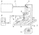
- FIG. 2 schematically illustrates an installation of laser recharging which can be used according to the invention.
- This installation includes a power laser 20 which delivers a beam 21 of coherent and monochromatic light.
- the beam laser 21 propagates in one direction, homogeneously, and has only one wavelength.
- the beam divergence is very weak.
- a set of deflection mirrors 22 and 23 makes it possible to transport the laser beam 21 as far as a focusing head 24.
- the focusing head 24 returns the laser beam 21 to the surface to recharge the substrate 10 with a tool such as a matrix of hot forging.
- the focusing head 24 is adapted for focus the laser beam 21 so that it strikes the substrate 10 along an impact area 25 of small area, by example a surface with a diameter between 0.5 and 5 mm approx.
- a powder distributor 26 serves as a container containing a metal alloy powder (s) with high heat resistance intended to form the reloading on the substrate 10 of the matrix.
- the powder distributor 26 is adapted to fluidify the powder to using a neutral gas such as argon or helium, and for the pneumatically transport to a projection nozzle 27 by powder supply lines 28.
- the projection nozzle 27 is suitable for shaping the fluidized powder jet in nozzle outlet, to produce a convergent powder jet coming from strike the same impact zone 25 of the substrate 10.
- the powder jet fluidized at the outlet of the nozzle should be as much confused as possible with the shape of the laser beam 21 in the impact zone 25. From preferably, the fluidized powder jet is coaxial with the laser beam 21 upon its arrival on the impact zone 25.
- the powder distributor 26 is of a type allowing precisely control the mass flow of metal powder, to obtain excellent reproducibility and perfect regularity parameters which have a direct influence on the regularity and quality of the reloads obtained.
- Regularity reloading significantly reduces the time and final machining costs of the active surface of the tool. This regularity also makes it possible to reduce the thickness of the reloading, and therefore the amount of material to use.
- the laser beam is oriented to be close to the vertical of the surface of the substrate 10 to be recharged.
- the orifice of projection nozzle 27 is kept at a distance constant of the surface to be recharged, approximately 10 mm.
- Substrate 10 is placed on a table 29 which is moved in the horizontal plane in two directions X and Y by controlled drive means by a numerical control 30. By this displacement, the impact zone 25 of the laser beam and powder coming out of the nozzle projection 27 is moved gradually and regularly on the surface of the substrate 10 to be recharged.
- the laser beam 21 melts the powder of metal alloy (s), which is welded to the substrate 10 metallic and gradually forms, after cooling, the layer of metal alloy (s) with high heat resistance 8 of which the external surface forms the active surface 7 of the forging tool hot.
- Figure 3 illustrates the progressive reloading, by displacement of the substrate 10 in the direction 31.
- the laser beam 21 melts the powder of metal alloy (s), which welds to substrate 10 and forms gradually, after cooling, a deposition bead 32.
- s metal alloy
- the power laser 20 can be a continuous CO 2 laser, with a power of 5 kW, associated with a coaxial projection nozzle 27 in which the fluidized metal powder is brought in a helical movement coaxial with the laser beam.
- the substrate 10 can advantageously be carried by a support for machine parts with numerical control four axes, allowing the horizontal displacements X and Y, allowing the vertical displacement Z relative to the projection nozzle 27, and allowing a rotation along a horizontal axis .
- the fusion of the alloy or alloys of high heat resistance, for their deposition by fusion on a substrate 10 of hot forging tool is carried out at by means of a power laser 20.
- High alloy metal alloys heat resistance are sprayed onto the substrate 10 in the impact zone 25 of the beam 21 coming from the power laser 20.
- the projection of metal alloys to high heat resistance in powder form is carried out by means of a projection nozzle 27 coaxial around the laser beam 21.
- the metal alloy (s) with high heat resistance can advantageously be of the cobalt-based superalloy type or nickel.
- the superalloy (s) can be chosen from the family of nickel-based superalloys, including superalloys known under the brands INCONEL 718 or ASTROLOY.
- the composition of the INCONEL 718 alloy is as follows, in percent by weight: carbon 0.038; chromium 18.50; molybdenum 3.00; titanium 0.95; aluminum 0.55; niobium 5.25; iron 18.00; the remains in nickel.
- composition of the ASTROLOY alloy is as follows, in weight percent: carbon 0.025; chromium 15.00; molybdenum 5.00; cobalt 18.00; titanium 3.50; aluminum 4.00; 0.025 boron; 0.050 zirconium; the rest in nickel.
- cobalt-based superalloy known as GRADE 6, the composition of which is as follows, in percent in weight: carbon 1.00; chromium 28.00; tungsten 4.00; the rest in cobalt.
- the duration of life of hot forging dies produced according to several techniques was 30,000 pieces for a nitrided steel matrix of reference X 38 Cr Mo V 5 nitrided, of 120,000 parts with a matrix reloaded with base superalloy cobalt GRADE 21 by means of an arc welding process, and 160,000 parts for a matrix reloaded with base superalloy cobalt GRADE 21 using a power laser. So a more than 30% increase in lifespan has been observed when recharging is carried out using a laser power.
Landscapes
- Engineering & Computer Science (AREA)
- Mechanical Engineering (AREA)
- Physics & Mathematics (AREA)
- Optics & Photonics (AREA)
- Plasma & Fusion (AREA)
- Chemical & Material Sciences (AREA)
- Materials Engineering (AREA)
- Metallurgy (AREA)
- Organic Chemistry (AREA)
- Forging (AREA)
- Laser Beam Processing (AREA)
Description
- la figure 1 illustre schématiquement, en coupe transversale, une structure d'outillage de forgeage à chaud selon un mode de réalisation particulier de l'invention ;
- la figure 2 illustre un dispositif de rechargement au laser pour la fabrication d'outils de forgeage à chaud selon l'invention ; et
- la figure 3 illustre schématiquement, à plus grande échelle, une buse coaxiale de projection de poudre métallique et de faisceau laser sur une zone d'impact, selon le dispositif de rechargement au laser de la figure 2.
Claims (10)
- Procédé de fabrication d'outils de forgeage à chaud ayant une couche superficielle en un ou plusieurs alliages métalliques à haute résistance à chaud sur un substrat (10) métallique, caractérisé en ce que la couche superficielle est réalisée par dépôt à l'état fondu dudit ou desdits alliages métalliques à haute résistance à chaud, et la fusion dudit ou desdits alliages métalliques à haute résistance à chaud pour le dépôt est effectuée au moyen d'un laser de puissance (20), qui assure simultanément la liaison métallurgique entre le ou les alliages métalliques de la couche superficielle et le métal du substrat (10).
- Procédé selon la revendication 1, caractérisé en ce qu'on projette le ou les alliages métalliques à haute résistance à chaud sous forme de poudre sur le substrat (10) dans la zone d'impact (25) du faisceau (21) provenant du laser de puissance (20).
- Procédé selon la revendication 2, caractérisé en ce qu'on projette le ou les alliages métalliques à haute résistance à chaud sous forme de poudre au moyen d'une buse de projection (27) coaxiale autour du faisceau laser (21).
- Procédé selon l'une quelconque des revendications 1 à 3, caractérisé en ce qu'on déplace la zone d'impact (25) du faisceau laser (21) sur le substrat (10) selon une vitesse de balayage contrôlée constante.
- Procédé selon l'une quelconque des revendications 1 à 4, caractérisé en ce que le ou les alliages métalliques à haute résistance à chaud sont du type superalliage à base de cobalt ou de nickel.
- Procédé selon la revendication 5, caractérisé en ce que le ou les superalliages sont choisis dans la famille des superalliages à base de nickel comprenant les superalliages connus sous les marques INCONEL 718 ou ASTROLOY.
- Procédé selon la revendication 5, caractérisé en ce que le ou les superalliages sont choisis dans la famille des superalliages à base de cobalt comprenant les superalliages connus sous les appellations GRADE 21 ou GRADE 6.
- Outil de forgeage à chaud, comprenant une couche superficielle (8) en un ou plusieurs alliages métalliques à haute résistance à chaud sur un substrat (10) métallique, caractérisé en ce que la couche superficielle d'alliage(s) métallique(s) à haute résistance à chaud (8) présente une structure cristallographique d'un dépôt à l'état fondu dudit ou desdit alliages métalliques à haute résistance à chaud effectué par fusion au laser de puissance, et en ce que la couche superficielle (8) et le substrat (10) sont liés par une liaison métallurgique.
- Outil selon la revendication 8, caractérisé en ce que le ou les alliages métalliques à haute résistance à chaud comprennent des superalliages à base de cobalt ou de nickel.
- Outil selon la revendication 9, caractérisé en ce que la couche superficielle d'alliage(s) métallique(s) à haute résistance à chaud (8) est en superalliage à base de nickel connu sous les marques INCONEL 718 ou ASTROLOY, ou en superalliage de cobalt connu sous les appellations GRADE 21 ou GRADE 6.
Applications Claiming Priority (2)
| Application Number | Priority Date | Filing Date | Title |
|---|---|---|---|
| FR9806981A FR2779074B1 (fr) | 1998-05-26 | 1998-05-26 | Procede de fabrication d'outils de forgeage a chaud, et outils obtenus par ce procede |
| FR9806981 | 1998-05-26 |
Publications (2)
| Publication Number | Publication Date |
|---|---|
| EP0960683A1 EP0960683A1 (fr) | 1999-12-01 |
| EP0960683B1 true EP0960683B1 (fr) | 2003-11-05 |
Family
ID=9526985
Family Applications (1)
| Application Number | Title | Priority Date | Filing Date |
|---|---|---|---|
| EP99420122A Expired - Lifetime EP0960683B1 (fr) | 1998-05-26 | 1999-05-21 | Procédé de fabrication d'outils de forgeage à chaud, et outils obtenus par ce procédé. |
Country Status (5)
| Country | Link |
|---|---|
| EP (1) | EP0960683B1 (fr) |
| AT (1) | ATE253431T1 (fr) |
| DE (2) | DE69912518T2 (fr) |
| ES (1) | ES2211012T3 (fr) |
| FR (1) | FR2779074B1 (fr) |
Families Citing this family (1)
| Publication number | Priority date | Publication date | Assignee | Title |
|---|---|---|---|---|
| JP5773070B2 (ja) * | 2012-03-30 | 2015-09-02 | 日立金属株式会社 | 熱間鍛造用金型 |
Family Cites Families (3)
| Publication number | Priority date | Publication date | Assignee | Title |
|---|---|---|---|---|
| JPS5767117A (en) * | 1980-10-08 | 1982-04-23 | Toshiba Corp | Heat treatment for metal mold |
| US4628178A (en) * | 1984-05-29 | 1986-12-09 | Sumitomo Electric Industries, Ltd. | Tool for warm and hot forgings and process for manufacturing the same |
| DE3505251A1 (de) * | 1985-02-15 | 1986-08-21 | Bündgens Maschinen Verwaltungen GmbH, 5100 Aachen | Verfahren und vorrichtung zur bildung eines kopfes an einem ende oder an beiden enden von metallstiften |
-
1998
- 1998-05-26 FR FR9806981A patent/FR2779074B1/fr not_active Expired - Fee Related
-
1999
- 1999-05-21 DE DE69912518T patent/DE69912518T2/de not_active Expired - Fee Related
- 1999-05-21 DE DE0960683T patent/DE960683T1/de active Pending
- 1999-05-21 ES ES99420122T patent/ES2211012T3/es not_active Expired - Lifetime
- 1999-05-21 EP EP99420122A patent/EP0960683B1/fr not_active Expired - Lifetime
- 1999-05-21 AT AT99420122T patent/ATE253431T1/de not_active IP Right Cessation
Also Published As
| Publication number | Publication date |
|---|---|
| ES2211012T3 (es) | 2004-07-01 |
| FR2779074A1 (fr) | 1999-12-03 |
| DE960683T1 (de) | 2000-04-20 |
| DE69912518D1 (de) | 2003-12-11 |
| FR2779074B1 (fr) | 2000-06-30 |
| EP0960683A1 (fr) | 1999-12-01 |
| DE69912518T2 (de) | 2004-07-08 |
| ATE253431T1 (de) | 2003-11-15 |
Similar Documents
| Publication | Publication Date | Title |
|---|---|---|
| CA2946844C (fr) | Procede et dispositif de preparation de toles d'acier aluminiees destinees a etre soudees puis durcies sous presse; flan soude correspondant | |
| EP2540433B1 (fr) | Procédé de rechargement d'un moule de verrerie par rechargement laser de poudres | |
| EP2090396B1 (fr) | Système et procédé de déposition de métaux par friction | |
| JP4083817B2 (ja) | 表面耐摩耗焼結機械部品及びその製造方法 | |
| KR101819084B1 (ko) | 표면 토폴로지 에너지 전달 보상에 의한 초합금 레이저 클래딩 | |
| EP0574290B1 (fr) | Procédé de pose d'un insert servant de revêtement protecteur sur une pièce en acier martensitique ou en alliage de titane | |
| CN1735714A (zh) | 控制激光金属成形硬质层的显微结构的方法 | |
| EP3359325B1 (fr) | Procede de chargement, piece metallique chargee ou rechargee | |
| EP0795377A1 (fr) | Procédé de réalisation d'un apport sur une zone localisée de pièce en superalliage | |
| US4864094A (en) | Process of fabricating a cutting edge on a tool and a cutting tool made thereby | |
| TW201722577A (zh) | 加工合金錠之系統及方法 | |
| EP1092496B1 (fr) | Méthode de réparation d'outillage en acier compacté utilisant un procédé de soudage TIG | |
| EP3969213B1 (fr) | Procédé de fabrication additive pour une pièce métallique | |
| EP0960683B1 (fr) | Procédé de fabrication d'outils de forgeage à chaud, et outils obtenus par ce procédé. | |
| WO2020080425A1 (fr) | Procédé de stratification de couche durcie et procédé de production pour article moulé stratifié | |
| EP0431093A1 (fr) | Fabrication de soupape en champignon | |
| Karşi et al. | Optimization of Laser Cladding Process Parameters of a Martensitic Stainless Steel Coating on GGG70L Ductile Cast Iron. | |
| EP0528720A1 (fr) | Procédé permettant le colaminage d'acier rapide sur un acier doux | |
| Koopmann et al. | Investigation of strategies to prevent crack formation in the hybrid-additive manufacturing process of tool components using directed energy deposition | |
| Wei | Multiple Material Selective Laser Melting: A New Approach | |
| US20260115794A1 (en) | Method for the additive manufacturing of a copper-steel monolithic article | |
| Lee et al. | Wear characteristics of STD61 tool steel according to repairing methods for Al porthole extrusion die: Direct metal deposition, welding, parent material | |
| JPH10299433A (ja) | エンジンのバルブガイド及び溶着加工装置 | |
| Pangsrivinij | High Throughput Functional Material Deposition Using a Laser Hot Wire Process | |
| JP2942299B2 (ja) | アルミニウム材の表面硬化用溶加材 |
Legal Events
| Date | Code | Title | Description |
|---|---|---|---|
| PUAI | Public reference made under article 153(3) epc to a published international application that has entered the european phase |
Free format text: ORIGINAL CODE: 0009012 |
|
| AK | Designated contracting states |
Kind code of ref document: A1 Designated state(s): AT BE CH DE ES FR GB IT LI LU |
|
| AX | Request for extension of the european patent |
Free format text: AL;LT;LV;MK;RO;SI |
|
| DET | De: translation of patent claims | ||
| 17P | Request for examination filed |
Effective date: 20000324 |
|
| AKX | Designation fees paid |
Free format text: AT BE CH DE ES FR GB IT LI LU |
|
| 17Q | First examination report despatched |
Effective date: 20011107 |
|
| GRAH | Despatch of communication of intention to grant a patent |
Free format text: ORIGINAL CODE: EPIDOS IGRA |
|
| GRAS | Grant fee paid |
Free format text: ORIGINAL CODE: EPIDOSNIGR3 |
|
| GRAA | (expected) grant |
Free format text: ORIGINAL CODE: 0009210 |
|
| AK | Designated contracting states |
Kind code of ref document: B1 Designated state(s): AT BE CH DE ES FR GB IT LI LU |
|
| REG | Reference to a national code |
Ref country code: GB Ref legal event code: FG4D Free format text: NOT ENGLISH |
|
| REG | Reference to a national code |
Ref country code: CH Ref legal event code: EP |
|
| REF | Corresponds to: |
Ref document number: 69912518 Country of ref document: DE Date of ref document: 20031211 Kind code of ref document: P |
|
| REG | Reference to a national code |
Ref country code: CH Ref legal event code: NV Representative=s name: ZIMMERLI, WAGNER & PARTNER AG |
|
| GBT | Gb: translation of ep patent filed (gb section 77(6)(a)/1977) |
Effective date: 20040218 |
|
| REG | Reference to a national code |
Ref country code: ES Ref legal event code: FG2A Ref document number: 2211012 Country of ref document: ES Kind code of ref document: T3 |
|
| PLBE | No opposition filed within time limit |
Free format text: ORIGINAL CODE: 0009261 |
|
| STAA | Information on the status of an ep patent application or granted ep patent |
Free format text: STATUS: NO OPPOSITION FILED WITHIN TIME LIMIT |
|
| 26N | No opposition filed |
Effective date: 20040806 |
|
| PGFP | Annual fee paid to national office [announced via postgrant information from national office to epo] |
Ref country code: GB Payment date: 20050414 Year of fee payment: 7 |
|
| PGFP | Annual fee paid to national office [announced via postgrant information from national office to epo] |
Ref country code: AT Payment date: 20050419 Year of fee payment: 7 |
|
| PGFP | Annual fee paid to national office [announced via postgrant information from national office to epo] |
Ref country code: ES Payment date: 20050422 Year of fee payment: 7 |
|
| PGFP | Annual fee paid to national office [announced via postgrant information from national office to epo] |
Ref country code: BE Payment date: 20050429 Year of fee payment: 7 |
|
| PGFP | Annual fee paid to national office [announced via postgrant information from national office to epo] |
Ref country code: CH Payment date: 20050513 Year of fee payment: 7 |
|
| PGFP | Annual fee paid to national office [announced via postgrant information from national office to epo] |
Ref country code: LU Payment date: 20050519 Year of fee payment: 7 Ref country code: FR Payment date: 20050519 Year of fee payment: 7 |
|
| PGFP | Annual fee paid to national office [announced via postgrant information from national office to epo] |
Ref country code: DE Payment date: 20050530 Year of fee payment: 7 |
|
| PG25 | Lapsed in a contracting state [announced via postgrant information from national office to epo] |
Ref country code: GB Free format text: LAPSE BECAUSE OF NON-PAYMENT OF DUE FEES Effective date: 20060521 Ref country code: AT Free format text: LAPSE BECAUSE OF NON-PAYMENT OF DUE FEES Effective date: 20060521 |
|
| PG25 | Lapsed in a contracting state [announced via postgrant information from national office to epo] |
Ref country code: ES Free format text: LAPSE BECAUSE OF NON-PAYMENT OF DUE FEES Effective date: 20060522 |
|
| PG25 | Lapsed in a contracting state [announced via postgrant information from national office to epo] |
Ref country code: LI Free format text: LAPSE BECAUSE OF NON-PAYMENT OF DUE FEES Effective date: 20060531 Ref country code: CH Free format text: LAPSE BECAUSE OF NON-PAYMENT OF DUE FEES Effective date: 20060531 Ref country code: BE Free format text: LAPSE BECAUSE OF NON-PAYMENT OF DUE FEES Effective date: 20060531 |
|
| PGFP | Annual fee paid to national office [announced via postgrant information from national office to epo] |
Ref country code: IT Payment date: 20060531 Year of fee payment: 8 |
|
| PG25 | Lapsed in a contracting state [announced via postgrant information from national office to epo] |
Ref country code: DE Free format text: LAPSE BECAUSE OF NON-PAYMENT OF DUE FEES Effective date: 20061201 |
|
| REG | Reference to a national code |
Ref country code: CH Ref legal event code: PL |
|
| GBPC | Gb: european patent ceased through non-payment of renewal fee |
Effective date: 20060521 |
|
| REG | Reference to a national code |
Ref country code: FR Ref legal event code: ST Effective date: 20070131 |
|
| REG | Reference to a national code |
Ref country code: ES Ref legal event code: FD2A Effective date: 20060522 |
|
| BERE | Be: lapsed |
Owner name: S.A. *TECHNOGENIA Effective date: 20060531 |
|
| PG25 | Lapsed in a contracting state [announced via postgrant information from national office to epo] |
Ref country code: FR Free format text: LAPSE BECAUSE OF NON-PAYMENT OF DUE FEES Effective date: 20060531 |
|
| PG25 | Lapsed in a contracting state [announced via postgrant information from national office to epo] |
Ref country code: LU Free format text: LAPSE BECAUSE OF NON-PAYMENT OF DUE FEES Effective date: 20060521 |
|
| PG25 | Lapsed in a contracting state [announced via postgrant information from national office to epo] |
Ref country code: IT Free format text: LAPSE BECAUSE OF NON-PAYMENT OF DUE FEES Effective date: 20070521 |