EP0960701A2 - Paper cutter - Google Patents
Paper cutter Download PDFInfo
- Publication number
- EP0960701A2 EP0960701A2 EP98122115A EP98122115A EP0960701A2 EP 0960701 A2 EP0960701 A2 EP 0960701A2 EP 98122115 A EP98122115 A EP 98122115A EP 98122115 A EP98122115 A EP 98122115A EP 0960701 A2 EP0960701 A2 EP 0960701A2
- Authority
- EP
- European Patent Office
- Prior art keywords
- guide rail
- paper
- slider
- stopper
- holder
- Prior art date
- Legal status (The legal status is an assumption and is not a legal conclusion. Google has not performed a legal analysis and makes no representation as to the accuracy of the status listed.)
- Granted
Links
Images



Classifications
-
- B—PERFORMING OPERATIONS; TRANSPORTING
- B26—HAND CUTTING TOOLS; CUTTING; SEVERING
- B26D—CUTTING; DETAILS COMMON TO MACHINES FOR PERFORATING, PUNCHING, CUTTING-OUT, STAMPING-OUT OR SEVERING
- B26D1/00—Cutting through work characterised by the nature or movement of the cutting member or particular materials not otherwise provided for; Apparatus or machines therefor; Cutting members therefor
- B26D1/01—Cutting through work characterised by the nature or movement of the cutting member or particular materials not otherwise provided for; Apparatus or machines therefor; Cutting members therefor involving a cutting member which does not travel with the work
- B26D1/12—Cutting through work characterised by the nature or movement of the cutting member or particular materials not otherwise provided for; Apparatus or machines therefor; Cutting members therefor involving a cutting member which does not travel with the work having a cutting member moving about an axis
- B26D1/14—Cutting through work characterised by the nature or movement of the cutting member or particular materials not otherwise provided for; Apparatus or machines therefor; Cutting members therefor involving a cutting member which does not travel with the work having a cutting member moving about an axis with a circular cutting member, e.g. disc cutter
- B26D1/157—Cutting through work characterised by the nature or movement of the cutting member or particular materials not otherwise provided for; Apparatus or machines therefor; Cutting members therefor involving a cutting member which does not travel with the work having a cutting member moving about an axis with a circular cutting member, e.g. disc cutter rotating about a movable axis
- B26D1/18—Cutting through work characterised by the nature or movement of the cutting member or particular materials not otherwise provided for; Apparatus or machines therefor; Cutting members therefor involving a cutting member which does not travel with the work having a cutting member moving about an axis with a circular cutting member, e.g. disc cutter rotating about a movable axis mounted on a movable carriage
- B26D1/185—Cutting through work characterised by the nature or movement of the cutting member or particular materials not otherwise provided for; Apparatus or machines therefor; Cutting members therefor involving a cutting member which does not travel with the work having a cutting member moving about an axis with a circular cutting member, e.g. disc cutter rotating about a movable axis mounted on a movable carriage for thin material, e.g. for sheets, strips or the like
-
- B—PERFORMING OPERATIONS; TRANSPORTING
- B26—HAND CUTTING TOOLS; CUTTING; SEVERING
- B26D—CUTTING; DETAILS COMMON TO MACHINES FOR PERFORATING, PUNCHING, CUTTING-OUT, STAMPING-OUT OR SEVERING
- B26D7/00—Details of apparatus for cutting, cutting-out, stamping-out, punching, perforating, or severing by means other than cutting
- B26D7/22—Safety devices specially adapted for cutting machines
-
- Y—GENERAL TAGGING OF NEW TECHNOLOGICAL DEVELOPMENTS; GENERAL TAGGING OF CROSS-SECTIONAL TECHNOLOGIES SPANNING OVER SEVERAL SECTIONS OF THE IPC; TECHNICAL SUBJECTS COVERED BY FORMER USPC CROSS-REFERENCE ART COLLECTIONS [XRACs] AND DIGESTS
- Y10—TECHNICAL SUBJECTS COVERED BY FORMER USPC
- Y10S—TECHNICAL SUBJECTS COVERED BY FORMER USPC CROSS-REFERENCE ART COLLECTIONS [XRACs] AND DIGESTS
- Y10S83/00—Cutting
- Y10S83/01—Safety devices
-
- Y—GENERAL TAGGING OF NEW TECHNOLOGICAL DEVELOPMENTS; GENERAL TAGGING OF CROSS-SECTIONAL TECHNOLOGIES SPANNING OVER SEVERAL SECTIONS OF THE IPC; TECHNICAL SUBJECTS COVERED BY FORMER USPC CROSS-REFERENCE ART COLLECTIONS [XRACs] AND DIGESTS
- Y10—TECHNICAL SUBJECTS COVERED BY FORMER USPC
- Y10T—TECHNICAL SUBJECTS COVERED BY FORMER US CLASSIFICATION
- Y10T83/00—Cutting
- Y10T83/768—Rotatable disc tool pair or tool and carrier
- Y10T83/7755—Carrier for rotatable tool movable during cutting
- Y10T83/7763—Tool carrier reciprocable rectilinearly
-
- Y—GENERAL TAGGING OF NEW TECHNOLOGICAL DEVELOPMENTS; GENERAL TAGGING OF CROSS-SECTIONAL TECHNOLOGIES SPANNING OVER SEVERAL SECTIONS OF THE IPC; TECHNICAL SUBJECTS COVERED BY FORMER USPC CROSS-REFERENCE ART COLLECTIONS [XRACs] AND DIGESTS
- Y10—TECHNICAL SUBJECTS COVERED BY FORMER USPC
- Y10T—TECHNICAL SUBJECTS COVERED BY FORMER US CLASSIFICATION
- Y10T83/00—Cutting
- Y10T83/869—Means to drive or to guide tool
- Y10T83/8748—Tool displaceable to inactive position [e.g., for work loading]
- Y10T83/8749—By pivotal motion
-
- Y—GENERAL TAGGING OF NEW TECHNOLOGICAL DEVELOPMENTS; GENERAL TAGGING OF CROSS-SECTIONAL TECHNOLOGIES SPANNING OVER SEVERAL SECTIONS OF THE IPC; TECHNICAL SUBJECTS COVERED BY FORMER USPC CROSS-REFERENCE ART COLLECTIONS [XRACs] AND DIGESTS
- Y10—TECHNICAL SUBJECTS COVERED BY FORMER USPC
- Y10T—TECHNICAL SUBJECTS COVERED BY FORMER US CLASSIFICATION
- Y10T83/00—Cutting
- Y10T83/869—Means to drive or to guide tool
- Y10T83/8776—Constantly urged tool or tool support [e.g., spring biased]
-
- Y—GENERAL TAGGING OF NEW TECHNOLOGICAL DEVELOPMENTS; GENERAL TAGGING OF CROSS-SECTIONAL TECHNOLOGIES SPANNING OVER SEVERAL SECTIONS OF THE IPC; TECHNICAL SUBJECTS COVERED BY FORMER USPC CROSS-REFERENCE ART COLLECTIONS [XRACs] AND DIGESTS
- Y10—TECHNICAL SUBJECTS COVERED BY FORMER USPC
- Y10T—TECHNICAL SUBJECTS COVERED BY FORMER US CLASSIFICATION
- Y10T83/00—Cutting
- Y10T83/869—Means to drive or to guide tool
- Y10T83/8821—With simple rectilinear reciprocating motion only
- Y10T83/8822—Edge-to-edge of sheet or web [e.g., traveling cutter]
-
- Y—GENERAL TAGGING OF NEW TECHNOLOGICAL DEVELOPMENTS; GENERAL TAGGING OF CROSS-SECTIONAL TECHNOLOGIES SPANNING OVER SEVERAL SECTIONS OF THE IPC; TECHNICAL SUBJECTS COVERED BY FORMER USPC CROSS-REFERENCE ART COLLECTIONS [XRACs] AND DIGESTS
- Y10—TECHNICAL SUBJECTS COVERED BY FORMER USPC
- Y10T—TECHNICAL SUBJECTS COVERED BY FORMER US CLASSIFICATION
- Y10T83/00—Cutting
- Y10T83/929—Tool or tool with support
- Y10T83/9457—Joint or connection
- Y10T83/9464—For rotary tool
Definitions
- the present invention relates to a paper cutter in which, in consideration of the safety of the cutter in the above structure of the guide rail, the safety is more secured.
- a guide rail 4 juxtaposed with a paper holding plate 3 is provided at an end portion of a paper stand 2 for cutting papers along the guide rail 4. Both ends of the guide rail 4 are fixed to one end each of two L-shaped arms 5 and the other end of each of two L-shaped arms 5 are rotatably mounted on both sides of the paper stand 2.
- Reference numeral 6 denotes a rotation shaft.
- a scale is indicated on the paper stand 2 for determining a size of paper.
- a groove 2a is formed perpendicularly to the guide rail 4.
- a paper abutting scale 8 is held in parallel with the guide rail 4 on a guide piece 7 within the groove 2a.
- a slider 9 is movably mounted on the guide rail 4, and a circular blade 10 (see Fig. 11) is mounted on the slider 9. Incidentally, a cutter mat 11 is laid at a position where the blade 10 is brought into contact with the paper stand 2.
- the papers are inserted into a gap between the guide rail 4 and the paper stand 2 by slightly rotating the guide rail 4.
- the papers are arranged at a predetermined position on the paper stand 2 by using the paper abutting scale 8.
- the guide rail 4 is returned back to the original position, and the paper holding plate 3 is pressed through the slider 9 and the papers are clamped between the paper holding plate 3 and the paper stand 2.
- the blade 10 is projected from a bottom surface of the paper holding plate 3 to make it possible to cut the papers. Then, when the slider 9 is displaced along the guide rail 4, the papers are cut into a predetermined size.
- the guide rail 4 is rotated to be held in a slanted posture at 90°, by which the slider 9 is prevented from being displaced.
- the blade 10 is not projected from the paper holding plate 3 by the spring force within the slider 9. Nevertheless, when the guide rail 4 and the slider 9 are simultaneously gripped or the slider 9 is pressed against the spring force, the blade 10 is projected from the paper holding plate 3 and dangerous, which causes the user to pay attention.
- An object of the present invention is to provide a paper cutter provided with a safety mechanism which may prevent a blade from being projected when it is not in use.
- a paper cutter comprising a guide rail provided slidably with a slider having a rotary blade, a pair of arms having an identical length to be connected between both ends of the guide rail and the paper stand in order to make the guide rail rotate in parallel with the paper stand between contacting position to and separating position from the paper stand, and when the guide rail contacts the paper stand, the rotary blade which is fixed on a holder to be moved up and down within the slider against a spring by being pushed down is made to project toward the paper stand, a stopper to prevent the rotary blade from being projected from the slider when the guide rail is rotated to separate from the paper stand is provided.
- the stopper is formed in such a manner as it, when the guide rail is separated from the paper stand, is rotated like a pendulum on a rotary shaft freely due to its unbalance weight on the shaft and a top thereof hooks an projection provided on the holder to prevent the holder from being displaced.
- the stopper is balanced to position where it avoids from abutting the projection when the guide rail contacts the paper stand.
- a recessed portion 12 provided with claws 4a and 4b up and down are formed in a longitudinal direction of the guide rail 4 in a side surface of the guide rail 4.
- a slide block 13 which is engaged with the recessed portion 12 is provided in the slider 9.
- L-shaped arms 5 having the same length for supporting both ends of the guide rail 4 are pivotally mounted at horizontal end portions thereof on the paper stand 2 by a shaft 6.
- the slider 9 is divided into a support portion 14 of the rotary blade 10 and an operating/sliding portion 15.
- the support portion 14 is composed of a back plate 16 in intimate contact with a surface of the rotary blade 10, a cutter cover 17 in contact with the back plate 16 from an upper side and a cutter lever 18 in contact with the side of the back plate 16.
- a rotary shaft 19 is provided on the back plate 16.
- the rotary blade 10 is rotatably mounted on the back plate 16 so that the rotary blade may be removable.
- the operating/sliding portion 15 is composed of the slide block 13, a slide plate 20 fixed to the slide block 13 so as to clamp the upper and lower claws 4a and 4b of the guide rail 4 for holding the slide block 13, a top cover 21 mounted on an upper portion of the slide plate 20, and a holder (support member) 22 coupled with the support portion 14 and movable up and down together with the support portion 14.
- the slide plate 20 is bent at its upper portion to form an upper plate 20a.
- a spring 24 is interposed in a space of a U-shaped plate 23 for covering the upper plate 20a.
- the holder 22 which is movable along the slide plate 20 is projected from the upper plate 20a and is fastened with the U-shaped plate 23, whereby an eaves portion 22a of the holder 22 is in pressing contact with the lower surface of the upper plate 20a by a spring force of a spring 24.
- the top cover 21 is fit around the U-shaped plate 23.
- the joint portion between the slide block 13 and the slide plate 20 is formed into a recessed portion where a stopper 25 is provided as a safety mechanism.
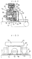
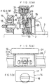
- the stopper 25 is pivoted free at an intermediate portion in a longitudinal direction of the guide rail, and, viewing in Fig. 4, the stopper 25 is formed in such a manner as a top end 25a of the stopper, by the moment in clockwise direction due to the unbalanced weight of the stopper 25, when the guide rail contacts the paper stand 2, is avoided from being engaged with a projection 22b of the holder 22.
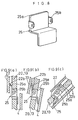
- the stopper 25 is formed generally in S-letter shape and extended vertically. And, at its upper portion it is provided with bearing portion 25b and pivoted, as shown in Fig. 4, at the joining portion at which the slide block 13 and slide plate 20 are contacted, so that the top end 25a of the stopper 25 is positioned at the position adjacent to the engaging position with the projection 22b formed on the side surface of the holder 22.
- the stopper 25 is postured substantially in the vertical direction and is out of contact with the projection 22b formed on the side surface of the holder 22. Then, if the top cover 21 is pressed, the rotary blade 10 is projected downwardly from the paper holding plate 3.
- the stopper 25 in the vicinity of the holder 22 is effected by the moment of rotation in the anti-clockwise direction caused by its unbalanced weight. Accordingly, the top end 25a of the stopper 25 can be positioned in contact with the projection 22b formed on the side surface of the holder 22. Namely, even in the slanted condition as shown in Fig. 1(a), the stopper 25 can be brought into engagement with the projection 22b, and also in the 90° slanted condition as shown in Fig. 1(b), the engagement may be kept.
- the stopper is provided in the slider which, when cutting the paper, is postured vertically and when the slider is slanted, it prevents the rotary blade from being exposed.
Landscapes
- Life Sciences & Earth Sciences (AREA)
- Forests & Forestry (AREA)
- Engineering & Computer Science (AREA)
- Mechanical Engineering (AREA)
- Details Of Cutting Devices (AREA)
- Nonmetal Cutting Devices (AREA)
Abstract
Description
Claims (3)
- A paper cutter comprising a guide rail provided slidably with a slider having a rotary blade, a pair of arms having an identical length to be connected between both ends of the guide rail and the paper stand in order to make the guide rail in parallel with the paper stand between contacting position to and separating position from the paper stand, wherein, when the guide rail contacts the paper stand, the rotary blade which is fixed on a holder to be moved up and down within the slider against a spring by being pushed down is made to project toward the paper stand, and a stopper to prevent the rotary blade from being projected from the slider when the guide rail is rotated to be separated from the paper stand is provided.
- A paper cutter according to Claim 1, wherein the stopper is formed in such a manner as it, when the guide rail is separated from the paper stand, is rotated automatically on a shaft free due to its unbalanced weight and a top end thereof hooks an projection provided on the holder to prevent the holder from being displaced.
- A paper cutter according to Claim 1, wherein the stopper is in an unbalanced manner due to its weight to position where it avoids from abutting on the projection when the guide rail contacts the paper stand to cut papers.
Applications Claiming Priority (2)
| Application Number | Priority Date | Filing Date | Title |
|---|---|---|---|
| JP16620498A JP3385456B2 (en) | 1998-05-29 | 1998-05-29 | Paper cutting machine |
| JP16620498 | 1998-05-29 |
Publications (3)
| Publication Number | Publication Date |
|---|---|
| EP0960701A2 true EP0960701A2 (en) | 1999-12-01 |
| EP0960701A3 EP0960701A3 (en) | 1999-12-15 |
| EP0960701B1 EP0960701B1 (en) | 2003-05-07 |
Family
ID=15827030
Family Applications (1)
| Application Number | Title | Priority Date | Filing Date |
|---|---|---|---|
| EP98122115A Expired - Lifetime EP0960701B1 (en) | 1998-05-29 | 1998-11-23 | Paper cutter |
Country Status (4)
| Country | Link |
|---|---|
| US (1) | US6079307A (en) |
| EP (1) | EP0960701B1 (en) |
| JP (1) | JP3385456B2 (en) |
| DE (1) | DE69814360T2 (en) |
Cited By (1)
| Publication number | Priority date | Publication date | Assignee | Title |
|---|---|---|---|---|
| EP1232841A3 (en) * | 2001-02-16 | 2004-11-10 | Carl Manufacturing Co., Ltd. | Cutter cassette and cutting device using the same |
Families Citing this family (14)
| Publication number | Priority date | Publication date | Assignee | Title |
|---|---|---|---|---|
| US6460443B1 (en) * | 2001-01-12 | 2002-10-08 | Tex Year Industries Inc. | Device for cutting sheet materials |
| EP1406762B1 (en) | 2001-07-13 | 2006-02-22 | Xyron, Inc. | Cutter assembly for a master processing apparatus |
| USD501500S1 (en) * | 2003-01-24 | 2005-02-01 | Carl Jimuki Kabushiki Kaisha | Paper trimmer |
| JP4471338B2 (en) * | 2003-08-20 | 2010-06-02 | カール事務器株式会社 | Paper cutting machine |
| US7044042B2 (en) | 2003-11-20 | 2006-05-16 | Carl Manufacturing Usa, Inc. | Blade cutting assembly for sheet material |
| JP4646598B2 (en) * | 2004-11-02 | 2011-03-09 | カール事務器株式会社 | Paper cutting machine |
| US7415915B2 (en) * | 2005-04-05 | 2008-08-26 | Elmer's Products, Inc. | Cutting system having an interchangeable rotary blade cartridge |
| JP4586979B2 (en) * | 2005-05-13 | 2010-11-24 | 富士工業株式会社 | Cutting tool |
| WO2007084779A2 (en) * | 2006-01-20 | 2007-07-26 | Inovent Llc | Rolled media cutter |
| US7744519B2 (en) * | 2006-09-14 | 2010-06-29 | Pregis Innovative Packaging, Inc. | System and method for crumpling paper substrates |
| US20090013844A1 (en) * | 2007-04-10 | 2009-01-15 | Acco Brands Usa Llc | Sheet trimmer |
| US20090271993A1 (en) * | 2008-04-30 | 2009-11-05 | Semprini David M | Drywall cutting apparatus |
| JP5374419B2 (en) * | 2010-02-15 | 2013-12-25 | 康宏 前川 | Sheet cutter |
| KR102115095B1 (en) * | 2018-10-25 | 2020-05-26 | 허승택 | Cut-Out Device of Interior Firm |
Family Cites Families (14)
| Publication number | Priority date | Publication date | Assignee | Title |
|---|---|---|---|---|
| US909227A (en) * | 1907-04-18 | 1909-01-12 | Charles T Ridgely | Paper-trimmer. |
| FR1201720A (en) * | 1958-07-11 | 1960-01-05 | Cutting device for thin sheets and in particular for sheets of paper | |
| US3237497A (en) * | 1964-01-22 | 1966-03-01 | Lawrence H Cook | Device for cutting paper |
| US3301117A (en) * | 1965-04-30 | 1967-01-31 | Daniel E Spaulding | Paper cutter |
| US3532018A (en) * | 1968-07-02 | 1970-10-06 | Varityper Corp | Composing copy layout table and cutting device |
| JPH0616699Y2 (en) * | 1988-02-29 | 1994-05-02 | カール事務器株式会社 | Cutter blade support structure for paper cutter |
| US5303626A (en) * | 1990-11-09 | 1994-04-19 | Canon Kabushiki Kaisha | Cutting apparatus |
| US5103710A (en) * | 1991-03-19 | 1992-04-14 | Ross Scott S | Media handling and cutting device |
| US5425295A (en) * | 1992-05-26 | 1995-06-20 | The Fletcher-Terry Company | Sheet material cutter having pivotable head |
| JPH06262586A (en) * | 1993-03-16 | 1994-09-20 | Karl Jimuki Kk | Paper cutting machine |
| US5322001A (en) * | 1993-05-28 | 1994-06-21 | Fiskars Oy Ab | Paper cutter with circular blades |
| US5524515A (en) * | 1993-05-28 | 1996-06-11 | Fiskars Oy Ab | Support panel for a rotary paper cutter |
| US5802942A (en) * | 1995-10-10 | 1998-09-08 | Fiskars Inc. | Paper trimmer |
| WO1997039863A1 (en) * | 1996-04-25 | 1997-10-30 | Hunt Holdings, Inc. | Rotary trimmer on a blade biasing carriage |
-
1998
- 1998-05-29 JP JP16620498A patent/JP3385456B2/en not_active Expired - Fee Related
- 1998-10-21 US US09/176,204 patent/US6079307A/en not_active Expired - Fee Related
- 1998-11-23 EP EP98122115A patent/EP0960701B1/en not_active Expired - Lifetime
- 1998-11-23 DE DE69814360T patent/DE69814360T2/en not_active Expired - Fee Related
Cited By (1)
| Publication number | Priority date | Publication date | Assignee | Title |
|---|---|---|---|---|
| EP1232841A3 (en) * | 2001-02-16 | 2004-11-10 | Carl Manufacturing Co., Ltd. | Cutter cassette and cutting device using the same |
Also Published As
| Publication number | Publication date |
|---|---|
| DE69814360D1 (en) | 2003-06-12 |
| EP0960701A3 (en) | 1999-12-15 |
| DE69814360T2 (en) | 2003-12-11 |
| JPH11333792A (en) | 1999-12-07 |
| US6079307A (en) | 2000-06-27 |
| EP0960701B1 (en) | 2003-05-07 |
| JP3385456B2 (en) | 2003-03-10 |
Similar Documents
| Publication | Publication Date | Title |
|---|---|---|
| EP0960701B1 (en) | Paper cutter | |
| US6346793B1 (en) | Battery charger with a terminal protector | |
| US8474674B2 (en) | Tablet cutter | |
| FR2954916A3 (en) | MOTORIZED TOOL | |
| KR100524846B1 (en) | Cartridge | |
| US20040221703A1 (en) | Cutting unit | |
| JP2021178435A (en) | Binding tool | |
| FR2576054A1 (en) | NATURAL OR ARTIFICIAL SLATE CUTTING DEVICE FOR DIRECT USE ON A ROOF | |
| JPH05507035A (en) | Measuring and cutting equipment | |
| US20050199116A1 (en) | Cutting unit | |
| US4307505A (en) | Cutter-presser for 710 connector | |
| US20050005455A1 (en) | Device for cuttng through a bindng strip | |
| JP2024157171A (en) | Fixed cut-off machine for metalworking | |
| JPS591219Y2 (en) | Film opening device | |
| JPS6028561Y2 (en) | Circular saw | |
| US20060021482A1 (en) | Tool for cutting armored cables | |
| JPH05185395A (en) | Roll paper cutting device | |
| JP2000515674A (en) | Apparatus and method for securing individual lines to IDC contacts | |
| JPH11170109A (en) | Pipe cutter | |
| KR20070020632A (en) | Dry leaf tobacco semi automatic binding device | |
| JPS63169286A (en) | Cutter for paper | |
| JP2006044067A (en) | Flip-over saw | |
| JP2011133787A (en) | Optical fiber slant-cutting device and optical fiber slant-cutting method | |
| FR2613289A1 (en) | Bookbinding system employing a movable metal clamp and a mounting support | |
| GB2238392A (en) | Tiling tool |
Legal Events
| Date | Code | Title | Description |
|---|---|---|---|
| PUAI | Public reference made under article 153(3) epc to a published international application that has entered the european phase |
Free format text: ORIGINAL CODE: 0009012 |
|
| PUAL | Search report despatched |
Free format text: ORIGINAL CODE: 0009013 |
|
| AK | Designated contracting states |
Kind code of ref document: A2 Designated state(s): BE DE FR GB IT NL |
|
| AX | Request for extension of the european patent |
Free format text: AL;LT;LV;MK;RO;SI |
|
| AK | Designated contracting states |
Kind code of ref document: A3 Designated state(s): AT BE CH CY DE DK ES FI FR GB GR IE IT LI LU MC NL PT SE |
|
| AX | Request for extension of the european patent |
Free format text: AL;LT;LV;MK;RO;SI |
|
| 17P | Request for examination filed |
Effective date: 20000117 |
|
| AKX | Designation fees paid |
Free format text: AT BE CH CY DE DK LI |
|
| RBV | Designated contracting states (corrected) |
Designated state(s): BE DE FR GB IT NL |
|
| 17Q | First examination report despatched |
Effective date: 20020205 |
|
| GRAH | Despatch of communication of intention to grant a patent |
Free format text: ORIGINAL CODE: EPIDOS IGRA |
|
| GRAH | Despatch of communication of intention to grant a patent |
Free format text: ORIGINAL CODE: EPIDOS IGRA |
|
| GRAA | (expected) grant |
Free format text: ORIGINAL CODE: 0009210 |
|
| AK | Designated contracting states |
Designated state(s): BE DE FR GB IT NL |
|
| REG | Reference to a national code |
Ref country code: GB Ref legal event code: FG4D |
|
| REF | Corresponds to: |
Ref document number: 69814360 Country of ref document: DE Date of ref document: 20030612 Kind code of ref document: P |
|
| ET | Fr: translation filed | ||
| PLBE | No opposition filed within time limit |
Free format text: ORIGINAL CODE: 0009261 |
|
| STAA | Information on the status of an ep patent application or granted ep patent |
Free format text: STATUS: NO OPPOSITION FILED WITHIN TIME LIMIT |
|
| 26N | No opposition filed |
Effective date: 20040210 |
|
| PGFP | Annual fee paid to national office [announced via postgrant information from national office to epo] |
Ref country code: NL Payment date: 20081113 Year of fee payment: 11 Ref country code: DE Payment date: 20081121 Year of fee payment: 11 |
|
| PGFP | Annual fee paid to national office [announced via postgrant information from national office to epo] |
Ref country code: IT Payment date: 20081122 Year of fee payment: 11 |
|
| PGFP | Annual fee paid to national office [announced via postgrant information from national office to epo] |
Ref country code: FR Payment date: 20081113 Year of fee payment: 11 |
|
| PGFP | Annual fee paid to national office [announced via postgrant information from national office to epo] |
Ref country code: GB Payment date: 20081117 Year of fee payment: 11 |
|
| PGFP | Annual fee paid to national office [announced via postgrant information from national office to epo] |
Ref country code: BE Payment date: 20090126 Year of fee payment: 11 |
|
| BERE | Be: lapsed |
Owner name: *CARL MFG CO. LTD Effective date: 20091130 |
|
| REG | Reference to a national code |
Ref country code: NL Ref legal event code: V1 Effective date: 20100601 |
|
| GBPC | Gb: european patent ceased through non-payment of renewal fee |
Effective date: 20091123 |
|
| REG | Reference to a national code |
Ref country code: FR Ref legal event code: ST Effective date: 20100730 |
|
| PG25 | Lapsed in a contracting state [announced via postgrant information from national office to epo] |
Ref country code: NL Free format text: LAPSE BECAUSE OF NON-PAYMENT OF DUE FEES Effective date: 20100601 Ref country code: FR Free format text: LAPSE BECAUSE OF NON-PAYMENT OF DUE FEES Effective date: 20091130 Ref country code: BE Free format text: LAPSE BECAUSE OF NON-PAYMENT OF DUE FEES Effective date: 20091130 |
|
| PG25 | Lapsed in a contracting state [announced via postgrant information from national office to epo] |
Ref country code: DE Free format text: LAPSE BECAUSE OF NON-PAYMENT OF DUE FEES Effective date: 20100601 |
|
| PG25 | Lapsed in a contracting state [announced via postgrant information from national office to epo] |
Ref country code: GB Free format text: LAPSE BECAUSE OF NON-PAYMENT OF DUE FEES Effective date: 20091123 |
|
| PG25 | Lapsed in a contracting state [announced via postgrant information from national office to epo] |
Ref country code: IT Free format text: LAPSE BECAUSE OF NON-PAYMENT OF DUE FEES Effective date: 20091123 |