EP0960703A2 - Machine pour la coupe en continu par un couteau rotatif dans un plan horizontal - Google Patents
Machine pour la coupe en continu par un couteau rotatif dans un plan horizontal Download PDFInfo
- Publication number
- EP0960703A2 EP0960703A2 EP99830305A EP99830305A EP0960703A2 EP 0960703 A2 EP0960703 A2 EP 0960703A2 EP 99830305 A EP99830305 A EP 99830305A EP 99830305 A EP99830305 A EP 99830305A EP 0960703 A2 EP0960703 A2 EP 0960703A2
- Authority
- EP
- European Patent Office
- Prior art keywords
- blade
- bearing element
- machine
- rotation
- conveyor
- Prior art date
- Legal status (The legal status is an assumption and is not a legal conclusion. Google has not performed a legal analysis and makes no representation as to the accuracy of the status listed.)
- Granted
Links
Images


Classifications
-
- B—PERFORMING OPERATIONS; TRANSPORTING
- B26—HAND CUTTING TOOLS; CUTTING; SEVERING
- B26D—CUTTING; DETAILS COMMON TO MACHINES FOR PERFORATING, PUNCHING, CUTTING-OUT, STAMPING-OUT OR SEVERING
- B26D7/00—Details of apparatus for cutting, cutting-out, stamping-out, punching, perforating, or severing by means other than cutting
- B26D7/01—Means for holding or positioning work
-
- B—PERFORMING OPERATIONS; TRANSPORTING
- B26—HAND CUTTING TOOLS; CUTTING; SEVERING
- B26D—CUTTING; DETAILS COMMON TO MACHINES FOR PERFORATING, PUNCHING, CUTTING-OUT, STAMPING-OUT OR SEVERING
- B26D1/00—Cutting through work characterised by the nature or movement of the cutting member or particular materials not otherwise provided for; Apparatus or machines therefor; Cutting members therefor
- B26D1/01—Cutting through work characterised by the nature or movement of the cutting member or particular materials not otherwise provided for; Apparatus or machines therefor; Cutting members therefor involving a cutting member which does not travel with the work
- B26D1/12—Cutting through work characterised by the nature or movement of the cutting member or particular materials not otherwise provided for; Apparatus or machines therefor; Cutting members therefor involving a cutting member which does not travel with the work having a cutting member moving about an axis
- B26D1/25—Cutting through work characterised by the nature or movement of the cutting member or particular materials not otherwise provided for; Apparatus or machines therefor; Cutting members therefor involving a cutting member which does not travel with the work having a cutting member moving about an axis with a non-circular cutting member
- B26D1/26—Cutting through work characterised by the nature or movement of the cutting member or particular materials not otherwise provided for; Apparatus or machines therefor; Cutting members therefor involving a cutting member which does not travel with the work having a cutting member moving about an axis with a non-circular cutting member moving about an axis substantially perpendicular to the line of cut
- B26D1/28—Cutting through work characterised by the nature or movement of the cutting member or particular materials not otherwise provided for; Apparatus or machines therefor; Cutting members therefor involving a cutting member which does not travel with the work having a cutting member moving about an axis with a non-circular cutting member moving about an axis substantially perpendicular to the line of cut and rotating continuously in one direction during cutting
- B26D1/29—Cutting through work characterised by the nature or movement of the cutting member or particular materials not otherwise provided for; Apparatus or machines therefor; Cutting members therefor involving a cutting member which does not travel with the work having a cutting member moving about an axis with a non-circular cutting member moving about an axis substantially perpendicular to the line of cut and rotating continuously in one direction during cutting with cutting member mounted in the plane of a rotating disc, e.g. for slicing beans
-
- B—PERFORMING OPERATIONS; TRANSPORTING
- B26—HAND CUTTING TOOLS; CUTTING; SEVERING
- B26D—CUTTING; DETAILS COMMON TO MACHINES FOR PERFORATING, PUNCHING, CUTTING-OUT, STAMPING-OUT OR SEVERING
- B26D1/00—Cutting through work characterised by the nature or movement of the cutting member or particular materials not otherwise provided for; Apparatus or machines therefor; Cutting members therefor
- B26D1/01—Cutting through work characterised by the nature or movement of the cutting member or particular materials not otherwise provided for; Apparatus or machines therefor; Cutting members therefor involving a cutting member which does not travel with the work
- B26D1/46—Cutting through work characterised by the nature or movement of the cutting member or particular materials not otherwise provided for; Apparatus or machines therefor; Cutting members therefor involving a cutting member which does not travel with the work having an endless band-knife or the like
-
- B—PERFORMING OPERATIONS; TRANSPORTING
- B26—HAND CUTTING TOOLS; CUTTING; SEVERING
- B26D—CUTTING; DETAILS COMMON TO MACHINES FOR PERFORATING, PUNCHING, CUTTING-OUT, STAMPING-OUT OR SEVERING
- B26D7/00—Details of apparatus for cutting, cutting-out, stamping-out, punching, perforating, or severing by means other than cutting
- B26D7/27—Means for performing other operations combined with cutting
- B26D7/32—Means for performing other operations combined with cutting for conveying or stacking cut product
Definitions
- the present invention relates to industrial machines for cutting food products and in particular it pertains to a continuous cutting machine with its blade rotating in a horizontal plane.
- Cutting machines with blade rotating in the horizontal plane are employed in the food industry to cut products destined to be consumed in appropriately sized slices; this is the case for instance of certain large fish which, after the removal of parts not destined to human consumption, such as fins, tail and bones, are cut into slices, individually packaged and marketed.
- a slicing machine substantially corresponding to the preamble of claim 1, which in particular comprises a blade rotating in a horizontal plane and is provided with: tubular product conveyors having a discharge section opposite to the plane of rotation of the blade; a first bearing element for the products to be cut which is horizontally planar and is positioned between the conveyor and the blade; and lastly a second bearing element positioned inferiorly to the plane of rotation of the blade.
- the two bearing elements are fixed, mutually parallel, suitably distanced and shaped in such a way as to leave the rotating blade uncovered only for a limited angular portion of its plane of rotation.
- the tubular conveyors instead are movable and, rotating about the axis of rotation of the blade, interact with the bearing elements in such a manner as periodically to bring a portion of product into the space interposed between the two bearing elements, where the blade at each turn of the tubular conveyors periodically intercepts the product cutting a slice therefrom.
- the operating cndurance of the machine is linked to the capacity for accumulating products to be cut presented by the tubular conveyors.
- the products accumulated in the convcyors have been exhausted, it is necessary to stop the machine, replenish it with new products to be cut and start a new production cycle.
- the aim of the present invention therefore is to eliminate the aforementioned drawbacks.
- this aim is attained by a slicing machine wherein said one or each conveyor is immobile, and said first bearing element is provided with a surface which is able to rotate about the axis of rotation of the blade and which periodically intercepts the discharge section of said one or each conveyor supporting the products contained therein; said second bearing element being provided with a surface able to rotate about the axis of rotation of the blade in synchrony with the first bearing element; said first and second bearing elements being provided with continuous motion and being angularly offset from each other to subdivide the total rotation angle of the blade into two angle fractions, in the first whereof the products transit freely through the discharge section of said one or each conveyor until bearing against the second bearing element, whereupon they are traversed by the blade and are subdivided into two parts kept in mutual superposition contact, said condition being maintained until a first part of the product is sent by the second bearing element towards a discharge section of the machine, whilst a second overlying part of the product contained in said conveyor is taken up by the first
- the machine according to the invention having stationary conveyors, can operate with continuous cycle and can be fed without any need to stop the rotating blade.
- Such a feature allows to reduce cycle down times and makes the machine usable, in addition to autonomous usage conditions, also under employment conditions providing for the incorporation of the machine within more complex processing lines.
- the number 1 indicates in its entirety a cutting machine essentially comprising a cutting apparatus 23 contained within a metal case 14 and operatively interconnected with a plurality of tubular, vertical, conveyors, fastened superiorly to the case 14 and provided with discharge section 5 inferiorly open for feeding the products towards the machine 1.
- the machine 1 further comprises a transfer apparatus 20 whereby the products cut into slices by the cutting apparatus 23 are ejected outside the machine 1.
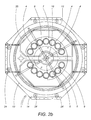
- the cutting apparatus 23 ( Figure 2a) essentially comprises a rotating drum 13 which is peripherally sustained by rollers 24, freely rotating, borne by the case 14, and it is driven by related motor driving means which allow the rotation with continuous motion of the drum 13 about a vertical axis of rotation 10 and which, in particular, are constituted by an internally toothed crown gear 25, integral with the drum 13, and by a pinion 26 meshing with the crown gear 25, driven in continuous motion by a gearmotor 27 associated to a top horizontal wall 28 of the case 14.
- the drum 13 sustains in a vertical plane, oriented radially thereto ( Figures 3 and 5), a continuous metal ribbon 2, provided with saw teeth.
- the ribbon 2 is enclosed in a horizontal loop elongated around a pair of pulleys 29,30 with parallel horizontal axes 29a, 30a, whereof one 30 is driven to rotate by related motor driving means which, in particular, are embodied by a conventional gearmotor 31, shown in Figure 2.
- Figure 3 shows the horizontal plane 6 relating to the upper branch 2s of the ribbon 2, which is opposite and proximate to the discharge surface 5 of the conveyors 4 and which directly involves the functionality of the cutting machine 1)
- the drum 13 also sustains two bearing elements 7,8 of the products which are positioned, in the vertical, bilaterally to the top horizontal branch 2s of the saw ribbon 2 ( Figure 4) and are angularly and horizontally offset with respect to each other in order to interact with the products of the conveyors at times and operating phases that differ and are distinct from each other.
- the first bearing element 7 of the products is horizontally planar and has its surface 9 shaped according to a portion of circle, in particular according to an arc of an annulus, which is integral to the drum 13, is centred on the axis 10 of rotation thereof and is vertically interposed between the plane 6 of rotation of the rotating blade 2s and the overlying conveyors 4; it is also located at such a distance from the axis 10 of rotation as to be able to oppose the discharge section 5 of the conveyors 4.
- the second product bearing element 8 is positioned inferiorly to the plane 6 of rotation of the blade 2 ( Figures 3 and 4) and presents a horizontal surface 11 with its plane parallel to the surface 9 of the first bearing element 7.
- the horizontal surface 11 of the second bearing element 8 is shaped substantially according to a portion of a circle which in particular comprises an annulus arc 11a centred on the axis or rotation 10 of the blade and joined to a rectilinear section 15 positioned in continuation of an extremity of the arc.
- the second bearing element 8 is also fastened to the drum 13, so that moving integrally therewith it rotates about the axis of rotation 10 of the blade 2s in synchrony with the first bearing element 7.
- the second bearing element 8 is provided with translation means 16, 19 ( Figure 6) which transfer towards a lower discharge section 12, located centrally to the case 14 in a position coaxial to the drum 13, the product parts cut by the blade 2s.
- the translation means in particular, comprise a continuous conveyor belt 16 associated to the surface 11 of the second bearing element 8; belt 16 which is wound around the second bearing element 8 in such a manner as to cover its surface 11 completely and which comprises a plurality of elements 17 for supporting the products concatenated in mutual succession and articulated around two axes 18x, 18z respectively parallel and transverse to the surface 11 of the second bearing element 8.
- the means for translating the cut products further comprise a conveyor 19 for discharging the cut products positioned between a terminal end 11t of the surface 11 of the second bearing element 8 and the product discharge section 12.
- the drum 13 further comprises ( Figure 7) a scraping blade 22 borne in vertical projection towards a horizontal wall 21 of the case 14.
- the wall 21 (which centrally bears the discharge section 12 of the cut products) is provided with a section 32 for discharging cutting scraps and is lapped with continuity by the blade 22 which, as a result of the dragging motion imparted thereto by the drum 13, intercepts the scraps and routes them onto the related discharge section 32 through which they are then evacuated outside the machine 1.
- said transfer apparatus 20 comprises in particular a continuous conveyor belt which is situated with respect to the case 14 with its own receiving end 33 positioned inferiorly to the section 5 for the discharge of the cut products.
- the belt allows to receive the cut products and to transfer them towards its own loading end 34 associated to a station for the further processing of the products, not shown herein, which can be embodied for instance by a station for packaging the product slices.
- the first bearing element 7 returns to intercept in succession the discharge section 5 of each conveyor 4; the lower part of the product (cut slice) thus progressively comes to separate from the overlying part of the product, whilst simultaneously advancing towards the discharge section 12 of the machine 1, by intervention of the second bearing element 8.
- the upper part of the product in the meantime is progressively taken up by the first bearing element 7 which again interposes itself between the plane 6 of rotation of the blade and the conveyor 4 and which sustains the products for the duration of the sweeping of the entire second angle fraction a; at the end whereof, the described cycle is repeated again in the same manner.
Landscapes
- Life Sciences & Earth Sciences (AREA)
- Forests & Forestry (AREA)
- Engineering & Computer Science (AREA)
- Mechanical Engineering (AREA)
- Processing Of Stones Or Stones Resemblance Materials (AREA)
- Crushing And Grinding (AREA)
- Mechanical Treatment Of Semiconductor (AREA)
- Sawing (AREA)
- Nonmetal Cutting Devices (AREA)
- Crushing And Pulverization Processes (AREA)
- Manufacturing And Processing Devices For Dough (AREA)
- Confectionery (AREA)
- Finish Polishing, Edge Sharpening, And Grinding By Specific Grinding Devices (AREA)
- Control And Other Processes For Unpacking Of Materials (AREA)
Applications Claiming Priority (2)
| Application Number | Priority Date | Filing Date | Title |
|---|---|---|---|
| IT1998RN000021A IT1305994B1 (it) | 1998-05-28 | 1998-05-28 | Macchina affettatrice continua con lama rotante in un pianoorizzontale. |
| ITRN980021 | 1998-05-28 |
Publications (3)
| Publication Number | Publication Date |
|---|---|
| EP0960703A2 true EP0960703A2 (fr) | 1999-12-01 |
| EP0960703A3 EP0960703A3 (fr) | 2000-08-09 |
| EP0960703B1 EP0960703B1 (fr) | 2003-02-05 |
Family
ID=11407189
Family Applications (1)
| Application Number | Title | Priority Date | Filing Date |
|---|---|---|---|
| EP99830305A Expired - Lifetime EP0960703B1 (fr) | 1998-05-28 | 1999-05-18 | Machine pour la coupe en continu par un couteau rotatif dans un plan horizontal |
Country Status (6)
| Country | Link |
|---|---|
| EP (1) | EP0960703B1 (fr) |
| AT (1) | ATE232155T1 (fr) |
| DE (1) | DE69905217D1 (fr) |
| ES (1) | ES2192374T3 (fr) |
| IT (1) | IT1305994B1 (fr) |
| PT (1) | PT960703E (fr) |
Families Citing this family (1)
| Publication number | Priority date | Publication date | Assignee | Title |
|---|---|---|---|---|
| CN110962168B (zh) * | 2019-11-13 | 2021-05-18 | 眉山光大塑料包装有限公司 | 一种泡沫板直切装置 |
Family Cites Families (4)
| Publication number | Priority date | Publication date | Assignee | Title |
|---|---|---|---|---|
| DE1782316A1 (de) * | 1968-08-14 | 1971-08-12 | A Gerrits Fa | Maschine zum aufeinanderfolgenden Schneiden von Fleisch,Speck u.dgl. |
| US4050339A (en) * | 1976-01-07 | 1977-09-27 | Soleri Richard A | Automatic carousel-type meat cutting machine |
| DE3170132D1 (en) * | 1980-09-04 | 1985-05-30 | Aew Eng Co Ltd | Apparatus for portioning meat |
| JPS6393593A (ja) * | 1986-10-04 | 1988-04-23 | 株式会社 中島製作所 | 冷凍食肉用スライサ−の可動まな板構造 |
-
1998
- 1998-05-28 IT IT1998RN000021A patent/IT1305994B1/it active
-
1999
- 1999-05-18 ES ES99830305T patent/ES2192374T3/es not_active Expired - Lifetime
- 1999-05-18 AT AT99830305T patent/ATE232155T1/de not_active IP Right Cessation
- 1999-05-18 EP EP99830305A patent/EP0960703B1/fr not_active Expired - Lifetime
- 1999-05-18 PT PT99830305T patent/PT960703E/pt unknown
- 1999-05-18 DE DE69905217T patent/DE69905217D1/de not_active Expired - Lifetime
Also Published As
| Publication number | Publication date |
|---|---|
| ITRN980021A1 (it) | 1999-11-28 |
| PT960703E (pt) | 2003-06-30 |
| ES2192374T3 (es) | 2003-10-01 |
| ATE232155T1 (de) | 2003-02-15 |
| EP0960703B1 (fr) | 2003-02-05 |
| EP0960703A3 (fr) | 2000-08-09 |
| DE69905217D1 (de) | 2003-03-13 |
| IT1305994B1 (it) | 2001-05-23 |
Similar Documents
| Publication | Publication Date | Title |
|---|---|---|
| SU856373A3 (ru) | Автоматическа упаковочна лини | |
| CN202828240U (zh) | 高速自动碗面投包机 | |
| US3386602A (en) | De-packaging apparatus and method | |
| US4216689A (en) | Weight controlled bread loaf slicer | |
| US4725184A (en) | Bag slitting and emptying machine | |
| KR200477424Y1 (ko) | 슬라이스 단무지 절단장치 | |
| CN112388690A (zh) | 一种黄桃罐头制作用切块装罐装置 | |
| US4145990A (en) | Apparatus for applying grated cheese to pizza shells | |
| US4543864A (en) | Stacking conveyor for product slicing machine | |
| US6351927B1 (en) | Device for portioning foodstuffs, in particular ground meat, to be packed in trays or the like | |
| EP0960703B1 (fr) | Machine pour la coupe en continu par un couteau rotatif dans un plan horizontal | |
| US6745658B2 (en) | Severing machine for articles of weblike material having a sharpening zone for the blades separate from the cutting zone | |
| US1761984A (en) | Mechanism for salvaging tin cans | |
| CN210479213U (zh) | 无纺布自动包装用切割装置 | |
| US1991033A (en) | Dicing machine | |
| CN201640363U (zh) | 直条米线生产线多刀切断装置 | |
| ITFI20000077A1 (it) | Macchina troncatrice per prodotti in materiale nastriforme e simili alame multiple con scarico su canali paralleli | |
| EP0495173B1 (fr) | Système pour transférer et vider des récipients | |
| US4244252A (en) | Onion conveyor and slicer | |
| EP2543604B1 (fr) | Dispositif de formation de groupes de paquets | |
| CN109129627B (zh) | 一种果类食品对切装置 | |
| US820762A (en) | Fruit-slicer. | |
| US1230227A (en) | Trimming or snipping machine. | |
| CN117656138B (zh) | 一种切分装置及食品裹粉设备 | |
| SU1685384A1 (ru) | Лини дл очистки и обрезки лука |
Legal Events
| Date | Code | Title | Description |
|---|---|---|---|
| PUAI | Public reference made under article 153(3) epc to a published international application that has entered the european phase |
Free format text: ORIGINAL CODE: 0009012 |
|
| AK | Designated contracting states |
Kind code of ref document: A2 Designated state(s): AT BE CH CY DE DK ES FI FR GB GR IE IT LI LU MC NL PT SE |
|
| AX | Request for extension of the european patent |
Free format text: AL;LT;LV;MK;RO;SI |
|
| PUAL | Search report despatched |
Free format text: ORIGINAL CODE: 0009013 |
|
| AK | Designated contracting states |
Kind code of ref document: A3 Designated state(s): AT BE CH CY DE DK ES FI FR GB GR IE IT LI LU MC NL PT SE |
|
| AX | Request for extension of the european patent |
Free format text: AL;LT;LV;MK;RO;SI |
|
| 17P | Request for examination filed |
Effective date: 20001002 |
|
| AKX | Designation fees paid |
Free format text: AT BE CH CY DE DK ES FI FR GB GR IE IT LI LU MC NL PT SE |
|
| AXX | Extension fees paid |
Free format text: AL PAYMENT 20001002;LT PAYMENT 20001002;LV PAYMENT 20001002;MK PAYMENT 20001002;RO PAYMENT 20001002;SI PAYMENT 20001002 |
|
| GRAH | Despatch of communication of intention to grant a patent |
Free format text: ORIGINAL CODE: EPIDOS IGRA |
|
| GRAH | Despatch of communication of intention to grant a patent |
Free format text: ORIGINAL CODE: EPIDOS IGRA |
|
| GRAA | (expected) grant |
Free format text: ORIGINAL CODE: 0009210 |
|
| AK | Designated contracting states |
Designated state(s): AT BE CH CY DE DK ES FI FR GB GR IE IT LI LU MC NL PT SE |
|
| AX | Request for extension of the european patent |
Extension state: AL LT LV MK RO SI |
|
| PG25 | Lapsed in a contracting state [announced via postgrant information from national office to epo] |
Ref country code: LI Free format text: LAPSE BECAUSE OF FAILURE TO SUBMIT A TRANSLATION OF THE DESCRIPTION OR TO PAY THE FEE WITHIN THE PRESCRIBED TIME-LIMIT Effective date: 20030205 Ref country code: GR Free format text: LAPSE BECAUSE OF FAILURE TO SUBMIT A TRANSLATION OF THE DESCRIPTION OR TO PAY THE FEE WITHIN THE PRESCRIBED TIME-LIMIT Effective date: 20030205 Ref country code: FI Free format text: LAPSE BECAUSE OF FAILURE TO SUBMIT A TRANSLATION OF THE DESCRIPTION OR TO PAY THE FEE WITHIN THE PRESCRIBED TIME-LIMIT Effective date: 20030205 Ref country code: CH Free format text: LAPSE BECAUSE OF FAILURE TO SUBMIT A TRANSLATION OF THE DESCRIPTION OR TO PAY THE FEE WITHIN THE PRESCRIBED TIME-LIMIT Effective date: 20030205 Ref country code: AT Free format text: LAPSE BECAUSE OF FAILURE TO SUBMIT A TRANSLATION OF THE DESCRIPTION OR TO PAY THE FEE WITHIN THE PRESCRIBED TIME-LIMIT Effective date: 20030205 |
|
| REG | Reference to a national code |
Ref country code: GB Ref legal event code: FG4D |
|
| REG | Reference to a national code |
Ref country code: CH Ref legal event code: EP |
|
| REG | Reference to a national code |
Ref country code: IE Ref legal event code: FG4D |
|
| REF | Corresponds to: |
Ref document number: 69905217 Country of ref document: DE Date of ref document: 20030313 Kind code of ref document: P |
|
| PG25 | Lapsed in a contracting state [announced via postgrant information from national office to epo] |
Ref country code: SE Free format text: LAPSE BECAUSE OF FAILURE TO SUBMIT A TRANSLATION OF THE DESCRIPTION OR TO PAY THE FEE WITHIN THE PRESCRIBED TIME-LIMIT Effective date: 20030505 Ref country code: DK Free format text: LAPSE BECAUSE OF FAILURE TO SUBMIT A TRANSLATION OF THE DESCRIPTION OR TO PAY THE FEE WITHIN THE PRESCRIBED TIME-LIMIT Effective date: 20030505 |
|
| PG25 | Lapsed in a contracting state [announced via postgrant information from national office to epo] |
Ref country code: DE Free format text: LAPSE BECAUSE OF FAILURE TO SUBMIT A TRANSLATION OF THE DESCRIPTION OR TO PAY THE FEE WITHIN THE PRESCRIBED TIME-LIMIT Effective date: 20030506 |
|
| PG25 | Lapsed in a contracting state [announced via postgrant information from national office to epo] |
Ref country code: LU Free format text: LAPSE BECAUSE OF NON-PAYMENT OF DUE FEES Effective date: 20030518 Ref country code: GB Free format text: LAPSE BECAUSE OF NON-PAYMENT OF DUE FEES Effective date: 20030518 Ref country code: CY Free format text: LAPSE BECAUSE OF FAILURE TO SUBMIT A TRANSLATION OF THE DESCRIPTION OR TO PAY THE FEE WITHIN THE PRESCRIBED TIME-LIMIT Effective date: 20030518 |
|
| PG25 | Lapsed in a contracting state [announced via postgrant information from national office to epo] |
Ref country code: IE Free format text: LAPSE BECAUSE OF NON-PAYMENT OF DUE FEES Effective date: 20030519 |
|
| PGFP | Annual fee paid to national office [announced via postgrant information from national office to epo] |
Ref country code: FR Payment date: 20030528 Year of fee payment: 5 |
|
| PGFP | Annual fee paid to national office [announced via postgrant information from national office to epo] |
Ref country code: PT Payment date: 20030530 Year of fee payment: 5 Ref country code: NL Payment date: 20030530 Year of fee payment: 5 |
|
| PG25 | Lapsed in a contracting state [announced via postgrant information from national office to epo] |
Ref country code: MC Free format text: LAPSE BECAUSE OF NON-PAYMENT OF DUE FEES Effective date: 20030531 |
|
| PGFP | Annual fee paid to national office [announced via postgrant information from national office to epo] |
Ref country code: ES Payment date: 20030619 Year of fee payment: 5 |
|
| REG | Reference to a national code |
Ref country code: PT Ref legal event code: SC4A Free format text: AVAILABILITY OF NATIONAL TRANSLATION Effective date: 20030502 |
|
| PGFP | Annual fee paid to national office [announced via postgrant information from national office to epo] |
Ref country code: BE Payment date: 20030716 Year of fee payment: 5 |
|
| LTIE | Lt: invalidation of european patent or patent extension |
Effective date: 20030205 |
|
| REG | Reference to a national code |
Ref country code: CH Ref legal event code: PL |
|
| ET | Fr: translation filed | ||
| REG | Reference to a national code |
Ref country code: ES Ref legal event code: FG2A Ref document number: 2192374 Country of ref document: ES Kind code of ref document: T3 |
|
| PLBE | No opposition filed within time limit |
Free format text: ORIGINAL CODE: 0009261 |
|
| STAA | Information on the status of an ep patent application or granted ep patent |
Free format text: STATUS: NO OPPOSITION FILED WITHIN TIME LIMIT |
|
| GBPC | Gb: european patent ceased through non-payment of renewal fee |
Effective date: 20030518 |
|
| 26N | No opposition filed |
Effective date: 20031106 |
|
| REG | Reference to a national code |
Ref country code: IE Ref legal event code: MM4A |
|
| PG25 | Lapsed in a contracting state [announced via postgrant information from national office to epo] |
Ref country code: ES Free format text: LAPSE BECAUSE OF NON-PAYMENT OF DUE FEES Effective date: 20040519 |
|
| PG25 | Lapsed in a contracting state [announced via postgrant information from national office to epo] |
Ref country code: BE Free format text: LAPSE BECAUSE OF NON-PAYMENT OF DUE FEES Effective date: 20040531 |
|
| PG25 | Lapsed in a contracting state [announced via postgrant information from national office to epo] |
Ref country code: PT Free format text: LAPSE BECAUSE OF NON-PAYMENT OF DUE FEES Effective date: 20041118 |
|
| BERE | Be: lapsed |
Owner name: *META MECCANICA S.R.L. Effective date: 20040531 |
|
| PG25 | Lapsed in a contracting state [announced via postgrant information from national office to epo] |
Ref country code: NL Free format text: LAPSE BECAUSE OF NON-PAYMENT OF DUE FEES Effective date: 20041201 |
|
| PG25 | Lapsed in a contracting state [announced via postgrant information from national office to epo] |
Ref country code: FR Free format text: LAPSE BECAUSE OF NON-PAYMENT OF DUE FEES Effective date: 20050131 |
|
| REG | Reference to a national code |
Ref country code: PT Ref legal event code: MM4A Effective date: 20041118 |
|
| NLV4 | Nl: lapsed or anulled due to non-payment of the annual fee |
Effective date: 20041201 |
|
| REG | Reference to a national code |
Ref country code: FR Ref legal event code: ST |
|
| PG25 | Lapsed in a contracting state [announced via postgrant information from national office to epo] |
Ref country code: IT Free format text: LAPSE BECAUSE OF NON-PAYMENT OF DUE FEES Effective date: 20050518 |
|
| REG | Reference to a national code |
Ref country code: ES Ref legal event code: FD2A Effective date: 20040519 |