EP0960713B1 - Dispositif de moulage par injection comportant des buses ayant des brides de fixation étendues - Google Patents
Dispositif de moulage par injection comportant des buses ayant des brides de fixation étendues Download PDFInfo
- Publication number
- EP0960713B1 EP0960713B1 EP99108853A EP99108853A EP0960713B1 EP 0960713 B1 EP0960713 B1 EP 0960713B1 EP 99108853 A EP99108853 A EP 99108853A EP 99108853 A EP99108853 A EP 99108853A EP 0960713 B1 EP0960713 B1 EP 0960713B1
- Authority
- EP
- European Patent Office
- Prior art keywords
- heated
- elongated
- melt
- distribution manifold
- cavity plate
- Prior art date
- Legal status (The legal status is an assumption and is not a legal conclusion. Google has not performed a legal analysis and makes no representation as to the accuracy of the status listed.)
- Expired - Lifetime
Links
- 238000001746 injection moulding Methods 0.000 title claims abstract description 16
- 239000000155 melt Substances 0.000 claims description 22
- 230000008602 contraction Effects 0.000 claims description 3
- 238000002347 injection Methods 0.000 description 4
- 239000007924 injection Substances 0.000 description 4
- 229910000831 Steel Inorganic materials 0.000 description 3
- 238000010438 heat treatment Methods 0.000 description 3
- 239000010959 steel Substances 0.000 description 3
- 238000001816 cooling Methods 0.000 description 2
- 239000012809 cooling fluid Substances 0.000 description 1
- 239000000463 material Substances 0.000 description 1
- 238000012986 modification Methods 0.000 description 1
- 230000004048 modification Effects 0.000 description 1
- 238000000465 moulding Methods 0.000 description 1
- 238000012856 packing Methods 0.000 description 1
- 238000005086 pumping Methods 0.000 description 1
- XLYOFNOQVPJJNP-UHFFFAOYSA-N water Substances O XLYOFNOQVPJJNP-UHFFFAOYSA-N 0.000 description 1
Images

Classifications
-
- B—PERFORMING OPERATIONS; TRANSPORTING
- B29—WORKING OF PLASTICS; WORKING OF SUBSTANCES IN A PLASTIC STATE IN GENERAL
- B29C—SHAPING OR JOINING OF PLASTICS; SHAPING OF MATERIAL IN A PLASTIC STATE, NOT OTHERWISE PROVIDED FOR; AFTER-TREATMENT OF THE SHAPED PRODUCTS, e.g. REPAIRING
- B29C45/00—Injection moulding, i.e. forcing the required volume of moulding material through a nozzle into a closed mould; Apparatus therefor
- B29C45/17—Component parts, details or accessories; Auxiliary operations
- B29C45/26—Moulds
- B29C45/27—Sprue channels ; Runner channels or runner nozzles
-
- B—PERFORMING OPERATIONS; TRANSPORTING
- B29—WORKING OF PLASTICS; WORKING OF SUBSTANCES IN A PLASTIC STATE IN GENERAL
- B29C—SHAPING OR JOINING OF PLASTICS; SHAPING OF MATERIAL IN A PLASTIC STATE, NOT OTHERWISE PROVIDED FOR; AFTER-TREATMENT OF THE SHAPED PRODUCTS, e.g. REPAIRING
- B29C45/00—Injection moulding, i.e. forcing the required volume of moulding material through a nozzle into a closed mould; Apparatus therefor
- B29C45/17—Component parts, details or accessories; Auxiliary operations
- B29C45/26—Moulds
- B29C45/27—Sprue channels ; Runner channels or runner nozzles
- B29C2045/2772—Means for fixing the nozzle to the manifold
Definitions
- This invention relates generally to multiple nozzle injection molding apparatus according to the preamble of claim 1.
- the invention relates to such apparatus wherein a number of nozzles extend from an elongated melt distribution manifold and each nozzle has an elongated mounting flange and is located by a locating and insulating bushing.
- Injection molding apparatus having a number of heated nozzles extending from an elongated heated melt distribution manifold into a cooled mold are well known.
- U.S. Patent Number 5,282,735 to Gellert which issued February 1, 1994, in some applications the front end of the nozzle is located in the mold and the rear end of the nozzle is attached to the melt distribution manifold by being screwed into it.
- Patent Number 5,429,491 to Gellert which issued July 4, 1995, this is usually achieved by the nozzle having an outer cylindrical collar portion which is either an integral part of the nozzle or removable and sits against a circular seat In the mold.
- these previous nozzles with a cylindrical collar portion have the disadvantage that the cylindrical collar portions prevent the pitch between adjacent nozzles or cavities along elongated melt distribution manifold being reduced as much as desired.
- a nozzle housing has a substantially flat rear face abutting a substantially flat front face of the manifold.
- the nozzle housing is pressed up against the manifold by an annular clamp ring which completely surrounds an enlarged upper portion of the nozzle housing.
- the ring has a side-wall portion with an annular lip. The lip abuts an engaged annular surface formed by the enlarged, upper portion of the nozzle housing.
- the nozzle manifold assembly further includes a nozzle centering ring positioned adjacent the clamp ring.
- EP-A-0695618 shows an injection molding nozzle with a collar having locating and retaining lug portions.
- the outer collar is made up of two removable semi-circular segments which interlock with the central body of the nozzle.
- Each of the semi-circular segments of the collar have a pair of spaced locating and retaining lug portions which extend outwardly to a longitudinal ridge. This provides sufficient thickness for a threaded hole at each lug portion to receive a screw to tighten the rear end of the nozzle securely against a melt distribution manifold.
- US-A-4663811 relates to a further configuration of an injection nozzle the upper portion of which is surrounded by an insulting bushing portion which is screwed via a valve bushing to a manifold 40.
- each nozzle has an elongated mounting flange at its rear end which allows the pitch between adjacent nozzles or cavities to be further reduced.
- the invention provides a multi-cavity injection molding apparatus having a plurality of heated nozzles extending in a row into a cooled mold from an elongated heated melt distribution manifold.
- Each heated nozzle has a rear end and an elongated main portion with a generally cylindrical outer surface and a melt bore extending therethrough to convey melt to a gate leading to a cavity.
- the melt distribution manifold has a melt passage extending therethrough with a number of branches extending outwardly from a common inlet portion. Each branch is aligned with the melt bore extending through one of the heated nozzles.
- the cooled mold includes a cooled cavity plate having a rear surface and an opening therein into which the heated nozzles extend.
- the opening has a surface which is spaced from the outer surfaces of the main portions of the heated nozzles.
- Each heated nozzle has an elongated flange portion with a front surface which provides a pair of mounting flanges extending outwardly in opposite directions adjacent the rear end of the heated nozzle.
- An insulating and locating bushing extends between each mounting flange and the cooled cavity plate to accurately locate the heated nozzle and space the front surface of the flange portion from the rear surface of the cooled cavity plate.
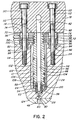
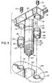
- Figures 1 and 2 show a multi-cavity injection molding apparatus or system wherein a number of heated nozzles 10 are mounted in a row in a mold 12 with their rear ends 14 extending from the front face 16 of a heated elongated melt distribution manifold 18. While only two heated nozzles 10 are shown for ease of illustration, normally this type of apparatus will have a larger number of heated nozzles 10 extending in a row from the heated elongated melt distribution manifold 18. Similarly, while the mold 12 can have a greater number of plates depending upon the application, in this case, only a top clamp plate 20, manifold plate 22 and a cavity plate 24 secured together by bolts 26, as well as a core plate 28 are shown for ease of illustration.
- the elongated melt distribution manifold 18 has an inlet portion 30 which is surrounded by a locating ring 32 secured to the top clamp plate 20 by screws 34.
- the elongated melt distribution manifold 18 is heated by an integral electrical heating element 36 and separated by an insulative air space 38 from the surrounding mold 12 which is cooled by pumping a cooling fluid such as water through cooling channels 40.
- a melt passage 42 extends from an inlet 44 in the inlet portion 30 of the elongated melt distribution manifold 18 and branches to extend through a central melt bore 46 in each heated nozzle 10 to gates 48 leading to cavities 50.
- Each branch 52 of the melt passage 42 extends through a two-piece nozzle seal 54 mounted in the front end 56 of one of the nozzles 10.
- Each two-piece nozzle seal 54 has an inner piece 58 with a pointed tip 60 aligned with one of the gates 48 and an outer piece 62 which is screwed into a threaded seat 64 in the front end 56 of the nozzle 10 to hold the inner piece 58 in place.
- each heated nozzle 10 has a steel elongated main portion 66 and a steel elongated flange portion 68 which are integrally brazed together in a vacuum furnace.
- the elongated flange portion 68 forms a pair of mounting flanges 70, 72 extending outwardly in opposite directions adjacent the rear end 14 of the heated nozzle 10.
- the mounting flanges 70, 72 each have openings 74, 76 extending therethrough in alignment with matching seats 78, 80 in the cavity plate 24.
- Matching steel insulating and locating bushings 82, 84 have rear ends 86, 88 extending into the openings 74, 76 in the mounting flanges 70, 72 and front ends 90, 92 extending into the matching seats 78, 80 in the cavity plate 24.
- the insulating and locating bushings 82, 84 have outwardly extending shoulders 94, 96 against which the front surface 98 of the flange portion 68 abuts to space the front surface 98 of the flange portion 68 from the rear surface 100 of the cooled cavity plate 24.
- the insulating and locating bushings 82, 84 locate the heated nozzles 10 with their elongated main portions 66 extending into an opening 102 in the cavity plate 24, with the pointed tip 60 of each two-piece seal 54 accurately aligned with one of the gates 48.
- the elongated main portion 66 of each heated nozzle 10 has an integral electrical heating element 104 extending around the melt bore 46 extending therethrough and a generally cylindrical outer surface 106 which is spaced from the surrounding surface 108 of the opening 102 in the cooled cavity plate 24.
- each heated nozzle 10 having the mounting flanges 70, 72 extending in opposite directions and the insulating and locating bushings 82, 84 extending from the mounting flanges 70, 72 on opposite sides of the opening 102 in the cavity plate 24 allows the heated nozzles 10 to be accurately located and positioned very closely together in a row, and the heated elongated melt distribution manifold 18 to be spaced rearwardly from the cooled cavity plate 24.
- the insulating and locating bushings 82, 84 are hollow and screws 110 extend therethrough from holes 112 through the elongated melt distribution manifold 18 into threaded bores 114 in the cavity plate 24.
- the holes 112 through the elongated melt distribution manifold 18 are sufficiently larger in diameter than the diameter of the mounting screws 110 to allow the elongated melt distribution manifold 18 to slide relative to the cavity plate 24 sufficiently to allow for thermal expansion and contraction of the elongated melt distribution manifold 18.
- a thermocouple element 116 extends through a hole 118 in the flange portion 68 of the heated nozzle 10 and through the insulative air space 122 around each heated nozzle 10 forwardly into an opening 120 in its front end 56 to monitor the operating temperature.
- the system is assembled as shown in Figures 1 and 2 with the heated nozzles 10 mounted very closely together and the insulating and locating bushing 82, 84 extending on opposite sides of the opening 102 in the cavity plate 24.
- electrical power is applied to the electrical heating elements 36, 104 in the elongated melt distribution manifold 18 and the heated nozzle 10 to heat the melt distribution manifold 18 and the nozzles 10 to a predetermined injection operating temperature.
- Pressurized melt is then applied from a molding machine (not shown) to the inlet 44 to the melt passage 42 according to a predetermined injection cycle. The melt flows through the elongated melt distribution manifold 18, nozzles 10, and gates 48 into the cavities 50.
- injection pressure is released.
- the mold 12 is then opened along the parting line 124 to eject the molded product. After ejection, the mold 12 is closed and the cycle is repeated continuously every 15 to 30 seconds with a frequency depending upon the wall thickness and the number and size of the cavities 50 and the exact material being molded.
Landscapes
- Engineering & Computer Science (AREA)
- Manufacturing & Machinery (AREA)
- Mechanical Engineering (AREA)
- Moulds For Moulding Plastics Or The Like (AREA)
- Injection Moulding Of Plastics Or The Like (AREA)
Claims (6)
- Dispositif de moulage par injection à cavités multiples, comportant une pluralité de buses (10) chauffées s'étendant en rangée dans un moule (12) refroidi depuis un collecteur de distribution de masse fondue chauffée (18) allongé, chaque buse (10) chauffée ayant une extrémité arrière (14) et une partie principale (66) allongée ayant une surface extérieure (106) globalement cylindrique, et un perçage pour masse fondue (46) s'étendant à travers elle, afin de transporter une masse fondue à une porte (48) menant à une cavité (50), le collecteur de distribution de masse fondue (18) ayant un passage pour masse fondue (42) s'étendant à travers lui, le passage pour masse fondue (42) ayant une pluralité de ramifications (52) s'étendant vers l'extérieur d'une partie d'entrée (44) commune, chaque ramification (52) étant alignée avec le perçage pour masse fondue (46) s'étendant par l'une des buses (10) chauffées, le moule (12) refroidi comprenant une plaque à cavité (24) refroidie, ayant une surface arrière et au moins une ouverture (102) en son sein, dans laquelle les buses (10) chauffées s'étendent, la au moins une ouverture (102) ayant une surface qui est espacée des surfaces extérieures (106) des parties principales (66) des buses (10) chauffées ;
chaque buse (10) chauffée ayant une partie formant bride (68) allongée, dotée d'une surface avant qui fournit une paire de brides de montage (70, 72) s'étendant vers l'extérieur dans des directions opposées adjacentes à l'extrémité arrière (14) de la buse chauffée (10), et une douille d'isolation et de positionnement (82, 84) s'étend entre chaque bride de montage (70, 72) et la plaque à cavité (24) refroidie, pour positionner de façon précise la buse (10) chauffée et espacer la surface avant (98) de la partie formant bride (68) vis-à-vis de la surface arrière (100) de la plaque à cavité (24) refroidie, caractérisé en ce que chaque douille d'isolation et de positionnement (82, 84) comporte une extrémité arrière (86) logée en une ouverture (74, 76) adaptée, ménagée dans l'une des parties formant bride (68), une extrémité avant (90, 92) logée dans un siège (78, 80), adapté dans la surface arrière (100) de la plaque à cavité (24), et un épaulement (94, 96) s'étendant vers l'extérieur, contre lequel la surface avant (98) de la partie formant bride (68) vient en butée, pour espacer la partie formant bride (68) de la plaque à cavité (24) refroidie et pour positionner de façon précise les buses (10) chauffées par rapport au moule (12). - Dispositif de moulage par injection selon la revendication 1, dans lequel chaque douille d'isolation et de positionnement (82, 84) est creuse ayant à travers elle un trou s'étendant en alignement avec un trou (112) ménagé dans le collecteur de distribution de masse fondue (18) et avec un trou taraudé (114) ménagé dans la plaque à cavité (24), et dans lequel des vis de montage (110) filetées s'étendent à travers les trous (112) dans le collecteur de distribution de masse fondue chauffée (18), à travers les trous alignés, ménagés dans les douilles d'isolation et de positionnement (82, 84), et à travers les perçages taraudés (114) alignés ménagés dans la plaque à cavité (24), pour fixer en place les buses (10) chauffées.
- Dispositif de moulage par injection selon la revendication 2, dans lequel la partie principale (66) cylindrique et la partie formant bride (68) allongée de chaque buse (10) chauffée sont réalisées d'une seule pièce.
- Dispositif de moulage par injection selon la revendication 3, dans lequel les trous (112) ménagés à travers le collecteur de distribution de masse fondue (18) sont d'un diamètre suffisamment supérieur au diamètre des vis de montage (110) s'étendant à travers eux pour permettre au collecteur de distribution de masse fondue (18) de coulisser suffisamment par rapport à la plaque à cavité (24) pour permettre la dilatation et la contraction thermiques du collecteur de distribution de masse fondue (18) allongé.
- Dispositif de moulage par injection selon la revendication 4, dans lequel la partie formant bride (68) allongée de chaque buse (10) chauffée est rectangulaire, avec une largeur non sensiblement supérieure au diamètre de la partie principale (66) cylindrique de la buse (10) chauffée.
- Ensemble pour utilisation dans un dispositif de moulage par injection selon l'une des revendications 1 à 5, l'ensemble comprenant :une buse (10) chauffée, ayant une partie principale (66) allongée dotée d'une surface globalement cylindrique, d'une partie formant bride (68) allongée et d'un perçage pour masse fondue (46) s'étendant à travers elle, la partie formant bride (68) ayant deux brides de montage (70, 72) s'étendant vers l'extérieur dans des directions opposées, de façon adjacente à une extrémité arrière (14) de la buse (10) chauffée, chacune desdites brides de montage (70, 72) ayant une ouverture (74, 76) ;deux douilles d'isolation et de positionnement (82, 84), chacune adaptée pour être logée dans l'une des ouvertures (74, 76) ménagées dans les brides de montage (70, 72), respectivement, et deux vis de montage (110), chacune adaptée pour être passée par l'une des douilles (82, 84) placée dans l'une des ouvertures (74, 76) ménagées dans la bride de montage (70, 72), respectivement.
Applications Claiming Priority (2)
| Application Number | Priority Date | Filing Date | Title |
|---|---|---|---|
| CA002239349A CA2239349A1 (fr) | 1998-05-29 | 1998-05-29 | Appareil d'injection muni de buses a brides de fixation allongees |
| CA2239349 | 1998-05-29 |
Publications (3)
| Publication Number | Publication Date |
|---|---|
| EP0960713A2 EP0960713A2 (fr) | 1999-12-01 |
| EP0960713A3 EP0960713A3 (fr) | 2000-09-13 |
| EP0960713B1 true EP0960713B1 (fr) | 2003-04-16 |
Family
ID=4162506
Family Applications (1)
| Application Number | Title | Priority Date | Filing Date |
|---|---|---|---|
| EP99108853A Expired - Lifetime EP0960713B1 (fr) | 1998-05-29 | 1999-05-04 | Dispositif de moulage par injection comportant des buses ayant des brides de fixation étendues |
Country Status (7)
| Country | Link |
|---|---|
| US (1) | US5980236A (fr) |
| EP (1) | EP0960713B1 (fr) |
| JP (1) | JP2000025075A (fr) |
| AT (1) | ATE237453T1 (fr) |
| CA (1) | CA2239349A1 (fr) |
| DE (1) | DE69906863T2 (fr) |
| SG (1) | SG77236A1 (fr) |
Families Citing this family (9)
| Publication number | Priority date | Publication date | Assignee | Title |
|---|---|---|---|---|
| CA2248553A1 (fr) * | 1998-09-30 | 2000-03-30 | Jobst Ulrich Gellert | Buse de moulage par injection vissee dans une base de montage |
| AU2001270006A1 (en) * | 2000-06-19 | 2002-01-02 | Progressive Components International Corporation | A core pin and sleeve and method of using same |
| US6755641B1 (en) * | 2000-09-01 | 2004-06-29 | Mold-Masters Limited | Stack injection molding apparatus with separately actuated arrays of valve gates |
| US7510392B2 (en) * | 2002-11-06 | 2009-03-31 | Mold-Masters (2007) Limited | Injection nozzle with a removable heater device having one or more heating elements |
| JP2005132075A (ja) * | 2002-11-06 | 2005-05-26 | Mold Masters Ltd | 板状ヒータを備えた射出ノズル |
| USD580461S1 (en) * | 2006-11-24 | 2008-11-11 | Heitec-Heisskanaltechnik Gmbh | Hot runner for injection moulding die |
| US7699600B2 (en) * | 2008-01-30 | 2010-04-20 | Husky Injection Molding Systems Ltd. | Flexible plate slot for a hot runner injection molding system |
| PL3157351T3 (pl) * | 2014-06-20 | 2019-11-29 | Live Tech S R L | System formowania wtryskowego dla produktu zawierającego tłuszcz |
| EP3680084B1 (fr) * | 2017-09-08 | 2022-11-02 | Nissei Asb Machine Co., Ltd. | Moule |
Family Cites Families (5)
| Publication number | Priority date | Publication date | Assignee | Title |
|---|---|---|---|---|
| CA1238161A (fr) * | 1985-12-02 | 1988-06-21 | Jobst U. Gellert | Fabrication de buses a fenetres configurables au choix pour le moulage par injection |
| CA2083413C (fr) * | 1992-11-19 | 2000-07-04 | Jobst Ulrich Gellert | Tuyere pour le moulage par injection, comportant un element chauffant, partiellement non chauffe |
| CA2127211C (fr) * | 1994-06-30 | 2004-09-21 | Jobst Ulrich Gellert | Buse de machine de moulage par injection a collier amovible |
| CA2129412C (fr) * | 1994-08-03 | 2004-10-26 | Jobst Ulrich Gellert | Buse de moulage par injection avec collet pourvu de pattes de positionnement et de retenue |
| US5507637A (en) * | 1995-03-02 | 1996-04-16 | Husky Injection Molding Systems Ltd. | Hot runner sliding nozzle |
-
1998
- 1998-05-29 CA CA002239349A patent/CA2239349A1/fr not_active Abandoned
- 1998-06-22 US US09/100,989 patent/US5980236A/en not_active Expired - Lifetime
-
1999
- 1999-05-04 AT AT99108853T patent/ATE237453T1/de not_active IP Right Cessation
- 1999-05-04 EP EP99108853A patent/EP0960713B1/fr not_active Expired - Lifetime
- 1999-05-04 DE DE69906863T patent/DE69906863T2/de not_active Expired - Lifetime
- 1999-05-17 SG SG1999002453A patent/SG77236A1/en unknown
- 1999-05-31 JP JP11152298A patent/JP2000025075A/ja not_active Withdrawn
Also Published As
| Publication number | Publication date |
|---|---|
| DE69906863D1 (de) | 2003-05-22 |
| ATE237453T1 (de) | 2003-05-15 |
| SG77236A1 (en) | 2000-12-19 |
| CA2239349A1 (fr) | 1999-11-29 |
| EP0960713A3 (fr) | 2000-09-13 |
| US5980236A (en) | 1999-11-09 |
| DE69906863T2 (de) | 2003-11-13 |
| JP2000025075A (ja) | 2000-01-25 |
| EP0960713A2 (fr) | 1999-12-01 |
Similar Documents
| Publication | Publication Date | Title |
|---|---|---|
| EP1152880B1 (fr) | Appareil de moulage par injection dote d'un joint d'etancheite de buse amovible | |
| CA2099334C (fr) | Insert de moulage par injection a orifice d'admission et cheville d'alignement | |
| CA2123360C (fr) | Buse de presse a injection avec deux douilles taraudees | |
| US5494433A (en) | Injection molding hot tip side gate seal having a circumferential rim | |
| US20020117777A1 (en) | Injection molding cooled cavity insert | |
| EP0816046B1 (fr) | Distributeurs à buse chauffés dans un plan commun interconnectés par des distributeurs de connexion | |
| US5429491A (en) | Injection molding nozzle with removable collar portion | |
| US6230384B1 (en) | Method of making an injection molding cylindrical manifold insert | |
| EP0743159B1 (fr) | Machine à mouler par injection à entrée d'injection latérale avec inserts d'entrée d'injection montés radialement | |
| EP1369217B1 (fr) | Buse d'injection vissée dans une base de montage | |
| CA2047461A1 (fr) | Distributeur de moulage par injection avec insertions amovibles | |
| CA2273517C (fr) | Rechauffeur de moulage par injection avec alesages de fonte traversants | |
| EP0743158B1 (fr) | Joint d'entrée d'injection latérale chaud avec rebord circonférentiel | |
| US5980236A (en) | Injection molding apparatus having nozzles with elongated mounting flanges | |
| US5536165A (en) | Injection molding apparatus with nozzle advanceable to mount side gate seals | |
| US5474440A (en) | Injection molding nozzle with collar having locating and retaining lug protions | |
| US6203310B1 (en) | Injection molding apparatus having mold cores with reverse taper | |
| US4795338A (en) | Mounting for injection molding nozzle | |
| EP0743157B1 (fr) | Dispositif à mouler par injection avec buse pouvant avancer pour le montage de joints d'entrée d'injection latérale | |
| EP0695618B1 (fr) | Buse de moulage par injection avec collier ayant des parties d'ergot de positionnement et de maintien | |
| HK1023964A (en) | Injection molding apparatus having nozzles with elongated mounting flanges |
Legal Events
| Date | Code | Title | Description |
|---|---|---|---|
| PUAI | Public reference made under article 153(3) epc to a published international application that has entered the european phase |
Free format text: ORIGINAL CODE: 0009012 |
|
| AK | Designated contracting states |
Kind code of ref document: A2 Designated state(s): AT BE CH CY DE DK ES FI FR GB IE IT LI LU NL PT SE |
|
| AX | Request for extension of the european patent |
Free format text: AL;LT;LV;MK;RO;SI |
|
| PUAL | Search report despatched |
Free format text: ORIGINAL CODE: 0009013 |
|
| AK | Designated contracting states |
Kind code of ref document: A3 Designated state(s): AT BE CH CY DE DK ES FI FR GB GR IE IT LI LU MC NL PT SE |
|
| AX | Request for extension of the european patent |
Free format text: AL;LT;LV;MK;RO;SI |
|
| RIC1 | Information provided on ipc code assigned before grant |
Free format text: 7B 29C 45/27 A, 7B 29C 45/36 B |
|
| 17P | Request for examination filed |
Effective date: 20001201 |
|
| AKX | Designation fees paid |
Free format text: AT BE CH CY DE DK ES FI FR GB IE IT LI LU NL PT SE |
|
| AXX | Extension fees paid |
Free format text: AL PAYMENT 20001201;LT PAYMENT 20001201;LV PAYMENT 20001201;RO PAYMENT 20001201;SI PAYMENT 20001201 |
|
| 17Q | First examination report despatched |
Effective date: 20010810 |
|
| GRAG | Despatch of communication of intention to grant |
Free format text: ORIGINAL CODE: EPIDOS AGRA |
|
| GRAG | Despatch of communication of intention to grant |
Free format text: ORIGINAL CODE: EPIDOS AGRA |
|
| GRAH | Despatch of communication of intention to grant a patent |
Free format text: ORIGINAL CODE: EPIDOS IGRA |
|
| GRAH | Despatch of communication of intention to grant a patent |
Free format text: ORIGINAL CODE: EPIDOS IGRA |
|
| GRAA | (expected) grant |
Free format text: ORIGINAL CODE: 0009210 |
|
| AK | Designated contracting states |
Designated state(s): AT BE CH CY DE DK ES FI FR GB IE IT LI LU NL PT SE |
|
| AX | Request for extension of the european patent |
Extension state: AL LT LV RO SI |
|
| PG25 | Lapsed in a contracting state [announced via postgrant information from national office to epo] |
Ref country code: NL Free format text: LAPSE BECAUSE OF FAILURE TO SUBMIT A TRANSLATION OF THE DESCRIPTION OR TO PAY THE FEE WITHIN THE PRESCRIBED TIME-LIMIT Effective date: 20030416 Ref country code: LI Free format text: LAPSE BECAUSE OF FAILURE TO SUBMIT A TRANSLATION OF THE DESCRIPTION OR TO PAY THE FEE WITHIN THE PRESCRIBED TIME-LIMIT Effective date: 20030416 Ref country code: FI Free format text: LAPSE BECAUSE OF FAILURE TO SUBMIT A TRANSLATION OF THE DESCRIPTION OR TO PAY THE FEE WITHIN THE PRESCRIBED TIME-LIMIT Effective date: 20030416 Ref country code: CH Free format text: LAPSE BECAUSE OF FAILURE TO SUBMIT A TRANSLATION OF THE DESCRIPTION OR TO PAY THE FEE WITHIN THE PRESCRIBED TIME-LIMIT Effective date: 20030416 Ref country code: BE Free format text: LAPSE BECAUSE OF FAILURE TO SUBMIT A TRANSLATION OF THE DESCRIPTION OR TO PAY THE FEE WITHIN THE PRESCRIBED TIME-LIMIT Effective date: 20030416 |
|
| REG | Reference to a national code |
Ref country code: GB Ref legal event code: FG4D |
|
| RIN1 | Information on inventor provided before grant (corrected) |
Inventor name: BABIN, DENIS L. Inventor name: GELLERT, JOBST ULRICH |
|
| REG | Reference to a national code |
Ref country code: CH Ref legal event code: EP |
|
| PG25 | Lapsed in a contracting state [announced via postgrant information from national office to epo] |
Ref country code: CY Free format text: LAPSE BECAUSE OF FAILURE TO SUBMIT A TRANSLATION OF THE DESCRIPTION OR TO PAY THE FEE WITHIN THE PRESCRIBED TIME-LIMIT Effective date: 20030504 |
|
| PG25 | Lapsed in a contracting state [announced via postgrant information from national office to epo] |
Ref country code: IE Free format text: LAPSE BECAUSE OF NON-PAYMENT OF DUE FEES Effective date: 20030505 |
|
| REF | Corresponds to: |
Ref document number: 69906863 Country of ref document: DE Date of ref document: 20030522 Kind code of ref document: P |
|
| REG | Reference to a national code |
Ref country code: IE Ref legal event code: FG4D |
|
| PG25 | Lapsed in a contracting state [announced via postgrant information from national office to epo] |
Ref country code: SE Free format text: LAPSE BECAUSE OF FAILURE TO SUBMIT A TRANSLATION OF THE DESCRIPTION OR TO PAY THE FEE WITHIN THE PRESCRIBED TIME-LIMIT Effective date: 20030716 Ref country code: PT Free format text: LAPSE BECAUSE OF FAILURE TO SUBMIT A TRANSLATION OF THE DESCRIPTION OR TO PAY THE FEE WITHIN THE PRESCRIBED TIME-LIMIT Effective date: 20030716 Ref country code: GB Free format text: LAPSE BECAUSE OF NON-PAYMENT OF DUE FEES Effective date: 20030716 Ref country code: DK Free format text: LAPSE BECAUSE OF FAILURE TO SUBMIT A TRANSLATION OF THE DESCRIPTION OR TO PAY THE FEE WITHIN THE PRESCRIBED TIME-LIMIT Effective date: 20030716 |
|
| LTIE | Lt: invalidation of european patent or patent extension |
Effective date: 20030416 |
|
| NLV1 | Nl: lapsed or annulled due to failure to fulfill the requirements of art. 29p and 29m of the patents act | ||
| PG25 | Lapsed in a contracting state [announced via postgrant information from national office to epo] |
Ref country code: ES Free format text: LAPSE BECAUSE OF FAILURE TO SUBMIT A TRANSLATION OF THE DESCRIPTION OR TO PAY THE FEE WITHIN THE PRESCRIBED TIME-LIMIT Effective date: 20031030 |
|
| REG | Reference to a national code |
Ref country code: CH Ref legal event code: PL |
|
| ET | Fr: translation filed | ||
| PLBE | No opposition filed within time limit |
Free format text: ORIGINAL CODE: 0009261 |
|
| STAA | Information on the status of an ep patent application or granted ep patent |
Free format text: STATUS: NO OPPOSITION FILED WITHIN TIME LIMIT |
|
| GBPC | Gb: european patent ceased through non-payment of renewal fee |
Effective date: 20030716 |
|
| REG | Reference to a national code |
Ref country code: IE Ref legal event code: MM4A |
|
| 26N | No opposition filed |
Effective date: 20040119 |
|
| PGFP | Annual fee paid to national office [announced via postgrant information from national office to epo] |
Ref country code: AT Payment date: 20040422 Year of fee payment: 6 |
|
| PGFP | Annual fee paid to national office [announced via postgrant information from national office to epo] |
Ref country code: LU Payment date: 20040426 Year of fee payment: 6 |
|
| PGFP | Annual fee paid to national office [announced via postgrant information from national office to epo] |
Ref country code: FR Payment date: 20040527 Year of fee payment: 6 |
|
| PG25 | Lapsed in a contracting state [announced via postgrant information from national office to epo] |
Ref country code: IT Free format text: LAPSE BECAUSE OF NON-PAYMENT OF DUE FEES Effective date: 20050504 Ref country code: AT Free format text: LAPSE BECAUSE OF NON-PAYMENT OF DUE FEES Effective date: 20050504 |
|
| PG25 | Lapsed in a contracting state [announced via postgrant information from national office to epo] |
Ref country code: FR Free format text: LAPSE BECAUSE OF NON-PAYMENT OF DUE FEES Effective date: 20060131 |
|
| REG | Reference to a national code |
Ref country code: FR Ref legal event code: ST Effective date: 20060131 |
|
| REG | Reference to a national code |
Ref country code: HK Ref legal event code: WD Ref document number: 1023964 Country of ref document: HK |
|
| PGFP | Annual fee paid to national office [announced via postgrant information from national office to epo] |
Ref country code: DE Payment date: 20180419 Year of fee payment: 20 |
|
| REG | Reference to a national code |
Ref country code: DE Ref legal event code: R071 Ref document number: 69906863 Country of ref document: DE |