EP0960742A1 - Druckmaschine - Google Patents
Druckmaschine Download PDFInfo
- Publication number
- EP0960742A1 EP0960742A1 EP99112030A EP99112030A EP0960742A1 EP 0960742 A1 EP0960742 A1 EP 0960742A1 EP 99112030 A EP99112030 A EP 99112030A EP 99112030 A EP99112030 A EP 99112030A EP 0960742 A1 EP0960742 A1 EP 0960742A1
- Authority
- EP
- European Patent Office
- Prior art keywords
- cassette
- printing
- housing
- band
- sleeve
- Prior art date
- Legal status (The legal status is an assumption and is not a legal conclusion. Google has not performed a legal analysis and makes no representation as to the accuracy of the status listed.)
- Granted
Links
- 238000007639 printing Methods 0.000 title claims abstract description 33
- 238000007651 thermal printing Methods 0.000 abstract 1
- 239000003086 colorant Substances 0.000 description 1
- 238000005516 engineering process Methods 0.000 description 1
- 238000004519 manufacturing process Methods 0.000 description 1
- 239000000463 material Substances 0.000 description 1
- 230000000149 penetrating effect Effects 0.000 description 1
Images

Classifications
-
- B—PERFORMING OPERATIONS; TRANSPORTING
- B41—PRINTING; LINING MACHINES; TYPEWRITERS; STAMPS
- B41J—TYPEWRITERS; SELECTIVE PRINTING MECHANISMS, i.e. MECHANISMS PRINTING OTHERWISE THAN FROM A FORME; CORRECTION OF TYPOGRAPHICAL ERRORS
- B41J17/00—Mechanisms for manipulating page-width impression-transfer material, e.g. carbon paper
- B41J17/32—Detachable carriers or holders for impression-transfer material mechanism
-
- B—PERFORMING OPERATIONS; TRANSPORTING
- B41—PRINTING; LINING MACHINES; TYPEWRITERS; STAMPS
- B41J—TYPEWRITERS; SELECTIVE PRINTING MECHANISMS, i.e. MECHANISMS PRINTING OTHERWISE THAN FROM A FORME; CORRECTION OF TYPOGRAPHICAL ERRORS
- B41J32/00—Ink-ribbon cartridges
-
- B—PERFORMING OPERATIONS; TRANSPORTING
- B41—PRINTING; LINING MACHINES; TYPEWRITERS; STAMPS
- B41J—TYPEWRITERS; SELECTIVE PRINTING MECHANISMS, i.e. MECHANISMS PRINTING OTHERWISE THAN FROM A FORME; CORRECTION OF TYPOGRAPHICAL ERRORS
- B41J35/00—Other apparatus or arrangements associated with, or incorporated in, ink-ribbon mechanisms
- B41J35/28—Detachable carriers or holders for ink-ribbon mechanisms
Definitions
- the invention relates to a printing press with a belt Cassette, the two rotatably mounted in a housing at a lateral distance Has sleeves, the tape being unwound from the one sleeve, on a printhead passed and wound onto the other sleeve and one on the housing Through hole for inserting a locating pin of the printing machine is appropriate.
- a printing press of the generic type has become known from DE 3723279 A1.
- the printer described there is suitable for the use of an ink ribbon cassette in which a Tape is included, which is unwound from a sleeve during printing, together with a record carrier between a thermal print head and one Pinch roller performed and finally wound up on another tube.
- Guide pins are provided that extend along the geometric axes of the sleeves extend and engage in holes in the cassette.
- the latter is on its side edges with two protruding cassette arms provided, on the end face of each one deflection element, d. H.
- a disadvantage of the known printing presses that no subsequent Adjustment of the position of the cassette and the tape is possible, so that due to Manufacturing tolerances of the dimensions of the cassette or the tape the optimal Positioning the ribbon relative to the print head is not guaranteed, so that - especially at higher printing speeds - not always good printing results arise.
- the invention is therefore based on the object of a printing press at the outset described type so that at all times an optimal position of the belt is guaranteed within the printing press.
- the invention proposes that the housing on a rests on the locating pin, which can be moved and fixed.
- the invention makes use of the mounting bolts of the machine on which one can insert the cassette.
- the cassette is from the state of the Technology also on the drive shaft and the brake shaft for the two sleeves with the Tape attached. Due to this three-point posture, a very correct one is achieved Assignment of the cassette or its respective working strand to other elements of the Machine or to the printing roller of the printing press.
- the collar can be attached to one of the printing presses facing surface and at an opposite, the free end of the Fit the locating pin on the adjacent surface of the cassette. Use too two collars, which immovably enclose the cassette between them, is conceivable.
- the cassette can consist of two identical, parallel housing halves, between which the sleeves are arranged.
- the locating pin then penetrates at least the through hole of one of the housing halves and the adjusting ring is present this half of the housing.
- the Printhead facing area must be enlarged to accommodate the center To create through hole.
- the through bore of the housing of the cassette can be through the bore of a Be formed bearing sleeve which is inserted into an opening in one half of the housing.
- the through hole is on a transverse plane of symmetry of the cassette in arranged near the edge, while the usable, free strand of the tape and the associated deflection elements are attached to the opposite end of the cassette.
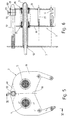
- the cassette 2 is inserted into the printing press 1 approximately perpendicular to the image plane.
- a rear wall 3 of the printing machine is spaced from two by two arranged through-toothed shafts penetrates, wherein, for example, the one shaft 4 with One drive motor is connected to the drive shaft, while the other shaft 5 is a a slip clutch connected brake shaft.
- the side distance of the two Shafts 4 and 5 correspond to the hole spacing 6 of the cassette 2.
- the cassette 2 receives a tape 7, which is preferably on a sleeve 8 Cardboard sleeve. If this band 7 in the sense of arrows 9, 10 and 11 of FIG. 2 should run, the band 7 with the sleeve 8 is initially assigned to the brake shaft 5. If you drive the drive shaft 4, it is unwound from the sleeve 8 and on a further sleeve 12 is wound which is penetrated by the drive shaft 4. Volume 7 is deflected via deflection elements 13 and 14 at the lower end of the cassette in FIG. The section located between these deflection elements 13 and 14 forms the working usable strand 15 of the ribbon 7. It is between a print head 16 of the Printing machine 1 and a printing roller 17 passed ( Figure 1).
- the housing half 19 is provided with an upper end Provide bulge 49 on which there is an opening 50.
- one Pressed bearing sleeve 51 which is preferably made of plastic.
- mounting bolt 52 By this mounting bolt 52 and the two shafts 4 and 5 is the cassette 2 of the figures 5 and 6 securely fixed in the printing press 1.
- the locating pin 52 is somewhat pointed at its free end. The same applies according to the drawing for waves 4 and 5. Otherwise the shafts of shafts 4 and 5 each pass through a bearing bush 53 of wall 3 is used for axial and radial storage.
- the cassette 2 of Figure 6 is narrower than cassettes, the thickness of which is approximately the length of the Waves 4 and 5, as far as they protrude beyond the wall 3, must be the exact one Position of the cassette 2 relative to the printing press 1 or its wall 3 by suitable To specify means.
- One possibility is that on the mounting pin 2 pushes an adjusting ring 54 with a clamping screw 55. It is easy to see that one by moving the adjusting ring 54 to the left, ie against the wall 3, through the displaces this stop formed and thereby the cassette 2 closer to the wall 3rd is approaching.
- FIG. 6 brings two cartridges 2 side by side into the printing press 1, each with one other particularly different colored band 7 can be loaded. It is also straightforward possible, first any labels or the like with the cassette 2 in the 6 to print position and then the cassette 2 completely to the left move by a second print on the side next to the first on the printed material to attach.
Landscapes
- Impression-Transfer Materials And Handling Thereof (AREA)
Abstract
Description
- Figur 1
- eine Seitenansicht einer Druckmaschine mit eingesetzter Kassette;
- Figur 5
- eine Ansicht der Kassette der Figur 1;
- Figur 6
- einen Schnitt gemäß der Linie VI-VI der Figur 5,
Claims (1)
- Druckmaschine mit einer ein Band (7) enthaltenden Kassette (2), die zwei in einem Gehäuse (18,19) im seitlichen Abstand angeordnete, drehbar gelagerte Hülsen (25,26,27,28) aufweist, wobei das Band (7) von der einen Hülse (26) abgespult, an einem Druckkopf (16) vorbei geführt und auf die andere Hülse (28) aufgespult wird und am Gehäuse (18,19) eine Durchgangsbohrung (50) zum Einstecken eines Aufnahmebolzens (52) der Druckmaschine (1) angebracht ist,
dadurch gekennzeichnet,
daß auf dem Aufnahmebolzen (52) ein verschieb- und festsetzbarer Stellring (54) angeordnet ist, an dem das Gehäuse (18,19) anliegt.
Applications Claiming Priority (3)
| Application Number | Priority Date | Filing Date | Title |
|---|---|---|---|
| DE4332608 | 1993-09-24 | ||
| DE4332608A DE4332608C2 (de) | 1993-09-24 | 1993-09-24 | Kassette |
| EP94113783A EP0645258B1 (de) | 1993-09-24 | 1994-09-02 | In Druckmaschinen einsetzbare Farbbandkassette |
Related Parent Applications (1)
| Application Number | Title | Priority Date | Filing Date |
|---|---|---|---|
| EP94113783A Division EP0645258B1 (de) | 1993-09-24 | 1994-09-02 | In Druckmaschinen einsetzbare Farbbandkassette |
Publications (2)
| Publication Number | Publication Date |
|---|---|
| EP0960742A1 true EP0960742A1 (de) | 1999-12-01 |
| EP0960742B1 EP0960742B1 (de) | 2002-03-13 |
Family
ID=6498568
Family Applications (2)
| Application Number | Title | Priority Date | Filing Date |
|---|---|---|---|
| EP94113783A Expired - Lifetime EP0645258B1 (de) | 1993-09-24 | 1994-09-02 | In Druckmaschinen einsetzbare Farbbandkassette |
| EP99112030A Expired - Lifetime EP0960742B1 (de) | 1993-09-24 | 1994-09-02 | Druckmaschine |
Family Applications Before (1)
| Application Number | Title | Priority Date | Filing Date |
|---|---|---|---|
| EP94113783A Expired - Lifetime EP0645258B1 (de) | 1993-09-24 | 1994-09-02 | In Druckmaschinen einsetzbare Farbbandkassette |
Country Status (6)
| Country | Link |
|---|---|
| US (1) | US5553952A (de) |
| EP (2) | EP0645258B1 (de) |
| JP (1) | JPH07228028A (de) |
| DE (3) | DE4332608C2 (de) |
| DK (1) | DK0645258T3 (de) |
| ES (1) | ES2148258T3 (de) |
Families Citing this family (21)
| Publication number | Priority date | Publication date | Assignee | Title |
|---|---|---|---|---|
| FR2725707A1 (fr) * | 1994-10-14 | 1996-04-19 | Ier | Cassette et rouleau pour ruban consommable, appareil recepteur, et procede de couplage en rotation du rouleau |
| DE19504135A1 (de) * | 1995-02-09 | 1996-04-04 | Esselte Meto Int Gmbh | Drucker |
| US5803625A (en) * | 1996-08-12 | 1998-09-08 | Taiwan Semiconductor Co., Ltd. | Bar code printing device |
| DE69727580T2 (de) * | 1997-11-27 | 2004-07-08 | Esselte N.V. | Nachfüllbare Farbbandkassette |
| WO1999043504A1 (de) * | 1998-02-27 | 1999-09-02 | Haug, Werner | Farbband-transporteinrichtung |
| US6888593B1 (en) | 1999-09-29 | 2005-05-03 | Fuji Photo Film Co., Ltd. | Anti-glare and anti-reflection film, polarizing plate, and image display device |
| US6428225B1 (en) * | 2000-02-18 | 2002-08-06 | Premark Feg L.L.C. | Printer cassette with label stock tensioner arm and associated printer |
| JPWO2006033430A1 (ja) * | 2004-09-24 | 2008-05-15 | ブラザー工業株式会社 | テープカセット及びテープ印字装置 |
| GB0502440D0 (en) * | 2005-02-07 | 2005-03-16 | Xaar Technology Ltd | Printing machines |
| EP2370267B1 (de) | 2008-12-25 | 2014-03-26 | Brother Kogyo Kabushiki Kaisha | Banddrucker |
| PL2370264T3 (pl) | 2008-12-25 | 2015-01-30 | Brother Ind Ltd | Kaseta z taśmą oraz drukarka taśmowa |
| CN101767490B (zh) * | 2008-12-29 | 2012-05-30 | 深圳市博思得科技发展有限公司 | 一种便携式条码标签打印机 |
| CN101850674B (zh) | 2009-03-31 | 2015-01-14 | 兄弟工业株式会社 | 带盒 |
| JP5445582B2 (ja) | 2009-03-31 | 2014-03-19 | ブラザー工業株式会社 | テープカセット |
| JP5282815B2 (ja) | 2009-03-31 | 2013-09-04 | ブラザー工業株式会社 | テープカセット |
| CN101850662B (zh) | 2009-03-31 | 2015-02-11 | 兄弟工业株式会社 | 带式打印装置 |
| JP5136503B2 (ja) | 2009-03-31 | 2013-02-06 | ブラザー工業株式会社 | テープカセット |
| US12296580B2 (en) | 2009-03-31 | 2025-05-13 | Brother Kogyo Kabushiki Kaisha | Tape cassette |
| US8641304B2 (en) | 2009-06-30 | 2014-02-04 | Brother Kogyo Kabushiki Kaisha | Tape cassette |
| JP5212550B2 (ja) | 2009-12-16 | 2013-06-19 | ブラザー工業株式会社 | テープカセット |
| EP2520437B1 (de) | 2009-12-28 | 2015-05-20 | Brother Kogyo Kabushiki Kaisha | Bandkassette |
Citations (2)
| Publication number | Priority date | Publication date | Assignee | Title |
|---|---|---|---|---|
| US4673304A (en) * | 1985-08-13 | 1987-06-16 | Sanders Associates, Inc. | Thermal printer ribbon cartridge for wide ribbons |
| US5174667A (en) * | 1990-03-30 | 1992-12-29 | Tokyo Electric Co., Ltd. | Transfer printer |
Family Cites Families (11)
| Publication number | Priority date | Publication date | Assignee | Title |
|---|---|---|---|---|
| DE141816C (de) * | ||||
| DD141816A2 (de) * | 1978-12-01 | 1980-05-21 | Hartmut Orlamuender | Farbbandkassette |
| DE2933815A1 (de) * | 1979-08-21 | 1981-03-26 | Siemens AG, 1000 Berlin und 8000 München | Vorrichtung zur bandfuehrung in farbbandkassetten |
| DE3426752A1 (de) * | 1984-07-20 | 1986-01-23 | Olympia Werke Ag, 2940 Wilhelmshaven | Farbbandkassettensystem fuer thermische drucker |
| US4776714A (en) * | 1986-07-15 | 1988-10-11 | Monarch Marking Systems, Inc. | Ink ribbon cassette with movable guide rolls |
| DE3741362A1 (de) * | 1987-12-07 | 1989-06-15 | Triumph Adler Ag | Traeger eines farbbandes mit vorrats- und aufwickelspule fuer schreib- und aehnliche maschinen |
| GB2250716A (en) * | 1990-11-20 | 1992-06-17 | Esselte Dymo Nv | Lid-responsive release of thermal printhead in printer using cassetted ink-ribbon. |
| DE4041991C2 (de) * | 1990-12-21 | 1994-06-30 | Mannesmann Ag | Farbbandvorrichtung, insbesondere für einen Zeilendrucker |
| US5073052A (en) * | 1991-02-23 | 1991-12-17 | Ncr Corporation | Reuseable ink ribbon cassette adjustable to different ribbon widths and method of use |
| JPH04301487A (ja) * | 1991-03-28 | 1992-10-26 | Kanzaki Paper Mfg Co Ltd | 転写リボンカセット |
| ZA929834B (en) * | 1991-12-19 | 1993-06-23 | Telkor Pty Ltd | Print ribbon cassettes. |
-
1993
- 1993-09-24 DE DE4332608A patent/DE4332608C2/de not_active Expired - Fee Related
-
1994
- 1994-09-02 ES ES94113783T patent/ES2148258T3/es not_active Expired - Lifetime
- 1994-09-02 DE DE59409338T patent/DE59409338D1/de not_active Expired - Fee Related
- 1994-09-02 EP EP94113783A patent/EP0645258B1/de not_active Expired - Lifetime
- 1994-09-02 DE DE59410083T patent/DE59410083D1/de not_active Expired - Fee Related
- 1994-09-02 EP EP99112030A patent/EP0960742B1/de not_active Expired - Lifetime
- 1994-09-02 DK DK94113783T patent/DK0645258T3/da active
- 1994-09-22 US US08/311,259 patent/US5553952A/en not_active Expired - Fee Related
- 1994-09-26 JP JP6229469A patent/JPH07228028A/ja active Pending
Patent Citations (2)
| Publication number | Priority date | Publication date | Assignee | Title |
|---|---|---|---|---|
| US4673304A (en) * | 1985-08-13 | 1987-06-16 | Sanders Associates, Inc. | Thermal printer ribbon cartridge for wide ribbons |
| US5174667A (en) * | 1990-03-30 | 1992-12-29 | Tokyo Electric Co., Ltd. | Transfer printer |
Also Published As
| Publication number | Publication date |
|---|---|
| JPH07228028A (ja) | 1995-08-29 |
| DK0645258T3 (da) | 2000-09-18 |
| EP0960742B1 (de) | 2002-03-13 |
| ES2148258T3 (es) | 2000-10-16 |
| DE59410083D1 (de) | 2002-04-18 |
| DE59409338D1 (de) | 2000-06-15 |
| EP0645258B1 (de) | 2000-05-10 |
| EP0645258A2 (de) | 1995-03-29 |
| DE4332608C2 (de) | 2003-01-09 |
| US5553952A (en) | 1996-09-10 |
| DE4332608A1 (de) | 1995-03-30 |
| EP0645258A3 (de) | 1997-11-26 |
Similar Documents
| Publication | Publication Date | Title |
|---|---|---|
| EP0960742B1 (de) | Druckmaschine | |
| DE19525115B4 (de) | Vorrichtung zum Transportieren von Werkstücken | |
| DE2500216A1 (de) | Lochsaegevorrichtung | |
| EP1345731A1 (de) | Gliederschürze zur abdeckung von maschinenteilen | |
| DE4202713A1 (de) | Fuehrung zum einziehen einer materialbahn in eine rollenrotationsdruckmaschine | |
| DE4323802A1 (de) | Verbesserungen bei Werkzeugen zur Formgebung von Behältnissen aus Pappe | |
| DE3226510C2 (de) | Universelle Papiertransporteinrichtung für Einzelblätter und Endlospapier in Zeilendruckeinrichtungen | |
| DE2258977A1 (de) | Typenband-schreibmaschine | |
| CH619399A5 (de) | ||
| DE60307803T2 (de) | Thermodruckmechanismus, besonders geeignet für bezahlungsendgeräte | |
| DE3332992A1 (de) | Drucker mit mosaikdruckkoepfen | |
| DE3437818A1 (de) | Punktmatrixdrucker | |
| DE69006233T2 (de) | Verfahren und Vorrichtung zum Einlegen eines Farbbandes. | |
| DE2135196C3 (de) | Bandkassette | |
| DE3524010C1 (de) | Papierfuehrung fuer Druckeinrichtungen mit in Abhaengigkeit von der Breite verschieblichen Papierfuehrungselementen | |
| EP0002796B1 (de) | Papiertransportvorrichtung für den Transport von Einzel- als auch Endlosformularen in einem schreibenden Gerät | |
| DE4205777C2 (de) | Drucker für die Verarbeitung von Aufzeichnungsträgern unterschiedlicher Dicke in Form von Einzelblättern und Endlosbahnen | |
| DE3101648C2 (de) | Papiervorschubeinrichtung | |
| DE602004002836T2 (de) | Aufzeichnungsgerät mit thermischem ZLinien-Druckkopf | |
| DE19801317C1 (de) | Vorrichtung zum Einführen von Endlos-Aufzeichnungsträgern in elektrografische Druck- oder Kopiereinrichtungen | |
| DE19630318C2 (de) | Verfahren zum Anordnen zweier Endlosbahnabschnitte nebeneinander in einer elektrografischen Druck- oder Kopiereinrichtung | |
| DE69810576T2 (de) | Thermobandeinheit, worin das thermoband eine anordnung von mindestens einem markierten strich enthält | |
| DE2550285B2 (de) | Antriebsmechanismus für ein endloses Farbband | |
| DE3334981C2 (de) | ||
| DE2020127A1 (de) | Schreibwerk mit Mosaikdruckkopf |
Legal Events
| Date | Code | Title | Description |
|---|---|---|---|
| PUAI | Public reference made under article 153(3) epc to a published international application that has entered the european phase |
Free format text: ORIGINAL CODE: 0009012 |
|
| AC | Divisional application: reference to earlier application |
Ref document number: 645258 Country of ref document: EP |
|
| AK | Designated contracting states |
Kind code of ref document: A1 Designated state(s): DE DK ES FR GB IT NL SE |
|
| 17P | Request for examination filed |
Effective date: 19991214 |
|
| RAP1 | Party data changed (applicant data changed or rights of an application transferred) |
Owner name: METO INTERNATIONAL GMBH |
|
| GRAG | Despatch of communication of intention to grant |
Free format text: ORIGINAL CODE: EPIDOS AGRA |
|
| 17Q | First examination report despatched |
Effective date: 20010411 |
|
| GRAG | Despatch of communication of intention to grant |
Free format text: ORIGINAL CODE: EPIDOS AGRA |
|
| GRAH | Despatch of communication of intention to grant a patent |
Free format text: ORIGINAL CODE: EPIDOS IGRA |
|
| GRAH | Despatch of communication of intention to grant a patent |
Free format text: ORIGINAL CODE: EPIDOS IGRA |
|
| REG | Reference to a national code |
Ref country code: GB Ref legal event code: IF02 |
|
| GRAA | (expected) grant |
Free format text: ORIGINAL CODE: 0009210 |
|
| AC | Divisional application: reference to earlier application |
Ref document number: 645258 Country of ref document: EP |
|
| AK | Designated contracting states |
Kind code of ref document: B1 Designated state(s): DE DK ES FR GB IT NL SE |
|
| PG25 | Lapsed in a contracting state [announced via postgrant information from national office to epo] |
Ref country code: IT Free format text: LAPSE BECAUSE OF FAILURE TO SUBMIT A TRANSLATION OF THE DESCRIPTION OR TO PAY THE FEE WITHIN THE PRESCRIBED TIME-LIMIT;WARNING: LAPSES OF ITALIAN PATENTS WITH EFFECTIVE DATE BEFORE 2007 MAY HAVE OCCURRED AT ANY TIME BEFORE 2007. THE CORRECT EFFECTIVE DATE MAY BE DIFFERENT FROM THE ONE RECORDED. Effective date: 20020313 Ref country code: FR Free format text: LAPSE BECAUSE OF FAILURE TO SUBMIT A TRANSLATION OF THE DESCRIPTION OR TO PAY THE FEE WITHIN THE PRESCRIBED TIME-LIMIT Effective date: 20020313 |
|
| REF | Corresponds to: |
Ref document number: 59410083 Country of ref document: DE Date of ref document: 20020418 |
|
| GBT | Gb: translation of ep patent filed (gb section 77(6)(a)/1977) |
Effective date: 20020521 |
|
| PG25 | Lapsed in a contracting state [announced via postgrant information from national office to epo] |
Ref country code: SE Free format text: LAPSE BECAUSE OF FAILURE TO SUBMIT A TRANSLATION OF THE DESCRIPTION OR TO PAY THE FEE WITHIN THE PRESCRIBED TIME-LIMIT Effective date: 20020613 Ref country code: DK Free format text: LAPSE BECAUSE OF FAILURE TO SUBMIT A TRANSLATION OF THE DESCRIPTION OR TO PAY THE FEE WITHIN THE PRESCRIBED TIME-LIMIT Effective date: 20020613 |
|
| PG25 | Lapsed in a contracting state [announced via postgrant information from national office to epo] |
Ref country code: ES Free format text: LAPSE BECAUSE OF FAILURE TO SUBMIT A TRANSLATION OF THE DESCRIPTION OR TO PAY THE FEE WITHIN THE PRESCRIBED TIME-LIMIT Effective date: 20020925 |
|
| EN | Fr: translation not filed | ||
| PLBE | No opposition filed within time limit |
Free format text: ORIGINAL CODE: 0009261 |
|
| STAA | Information on the status of an ep patent application or granted ep patent |
Free format text: STATUS: NO OPPOSITION FILED WITHIN TIME LIMIT |
|
| 26N | No opposition filed |
Effective date: 20021216 |
|
| PGFP | Annual fee paid to national office [announced via postgrant information from national office to epo] |
Ref country code: GB Payment date: 20030807 Year of fee payment: 10 |
|
| PGFP | Annual fee paid to national office [announced via postgrant information from national office to epo] |
Ref country code: NL Payment date: 20030812 Year of fee payment: 10 |
|
| PGFP | Annual fee paid to national office [announced via postgrant information from national office to epo] |
Ref country code: DE Payment date: 20030930 Year of fee payment: 10 |
|
| PG25 | Lapsed in a contracting state [announced via postgrant information from national office to epo] |
Ref country code: GB Free format text: LAPSE BECAUSE OF NON-PAYMENT OF DUE FEES Effective date: 20040902 |
|
| PG25 | Lapsed in a contracting state [announced via postgrant information from national office to epo] |
Ref country code: NL Free format text: LAPSE BECAUSE OF NON-PAYMENT OF DUE FEES Effective date: 20050401 Ref country code: DE Free format text: LAPSE BECAUSE OF NON-PAYMENT OF DUE FEES Effective date: 20050401 |
|
| GBPC | Gb: european patent ceased through non-payment of renewal fee |
Effective date: 20040902 |
|
| NLV4 | Nl: lapsed or anulled due to non-payment of the annual fee |
Effective date: 20050401 |