EP0960746A2 - Mécanisme pour classeurs à anneaux - Google Patents
Mécanisme pour classeurs à anneaux Download PDFInfo
- Publication number
- EP0960746A2 EP0960746A2 EP99301947A EP99301947A EP0960746A2 EP 0960746 A2 EP0960746 A2 EP 0960746A2 EP 99301947 A EP99301947 A EP 99301947A EP 99301947 A EP99301947 A EP 99301947A EP 0960746 A2 EP0960746 A2 EP 0960746A2
- Authority
- EP
- European Patent Office
- Prior art keywords
- ring binder
- binder mechanism
- plate members
- members
- mechanism according
- Prior art date
- Legal status (The legal status is an assumption and is not a legal conclusion. Google has not performed a legal analysis and makes no representation as to the accuracy of the status listed.)
- Withdrawn
Links
Images


Classifications
-
- B—PERFORMING OPERATIONS; TRANSPORTING
- B42—BOOKBINDING; ALBUMS; FILES; SPECIAL PRINTED MATTER
- B42F—SHEETS TEMPORARILY ATTACHED TOGETHER; FILING APPLIANCES; FILE CARDS; INDEXING
- B42F13/00—Filing appliances with means for engaging perforations or slots
- B42F13/16—Filing appliances with means for engaging perforations or slots with claws or rings
- B42F13/20—Filing appliances with means for engaging perforations or slots with claws or rings pivotable about an axis or axes parallel to binding edges
- B42F13/22—Filing appliances with means for engaging perforations or slots with claws or rings pivotable about an axis or axes parallel to binding edges in two sections engaging each other when closed
- B42F13/26—Filing appliances with means for engaging perforations or slots with claws or rings pivotable about an axis or axes parallel to binding edges in two sections engaging each other when closed and locked when so engaged, e.g. snap-action
Definitions
- This invention relates to a ring binder mechanism for retaining paper and, in particular, such a mechanism in which a significant amount of material may be saved.
- Conventional ring binder mechanisms usually include a pair of plates supported by a substantially rigid upper housing for relative pivotal movement.
- the housing extends over the entire length of the plates and is crimped on both lateral edges for engagement with the plates.
- To each of the plates are mounted a number of ring members which may be caused to be closed or opened, in order to allow paper to be retained thereby or retrieved therefrom.
- Such a ring binder mechanism requires metallic materials, e.g. steel, for the plates, housing and the plates. It is an object of the present invention to provide an improved ring binder mechanism in which less metallic material is required.
- a ring binder mechanism comprising means for supporting two plate members for relative pivotal movement, wherein a plurality of paper-retaining members are mounted to said plate members, wherein said plate members are pivotably movable relative to each other between a first configuration in which the paper-retaining members are closed and the angle between respective upper surfaces of the plate members is less than 180°, and a second configuration in which the paper-retaining members are open and the angle between respective upper surfaces of the plate members is more than 180°, wherein said supporting means comprises at least two supporting members engaging with said plate members, and wherein said plate members are retained by said supporting members in a position in which an edge of one of said plate members is in constant abutment with an edge of the other said plate member.
- a ring binder mechanism comprising means for supporting two plate members for relative pivotal movement, wherein a plurality of paper-retaining members are mounted to said plate members, wherein said plate members are pivotably movable relative to each other between a first configuration in which the paper-retaining members are closed and the angle between respective upper surfaces of the plate members is less than 180°, and a second configuration in which the paper-retaining members are open and the angle between respective upper surfaces of the plate members is more than 180°, and wherein said supporting means comprises at least two supporting members engaging with said plate members and allowing a majority of the upper surfaces of the plate members to be exposed to the environment.
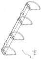
- FIG. 1 to 3B A first embodiment of a ring binder mechanism according to the present invention is shown in Figs. 1 to 3B as generally designated as 10.
- the ring binder mechanism 10 includes a pair of plates 12, to which are mounted two pairs of half-rings 14A, 14B. It can be seen that each of the plates 12 has an inner edge 16 which is in constant abutment with each other (see Figs. 1, 3A and 3B). Lugs 18 are provided adjacent to said inner edges 16 to assist in proper alignment of the plates 12.
- the plates 12 are supported for pivotal movement, and are retained into their abutting relation, by two types of structures, namely a pair of wires 20, and a pair of tabs 22. It should be understood that either of these two types of structures would suffice for the present invention, and they are here shown together simply for the purpose of convenience.
- each of the wires 20 is bent, extends over the upper surfaces of the plates 12, and is crimped at both sides for engagement with the outer edges of the plates 12 at four points.
- the wires 20 are tensioned and resilient, and thus bias the plates 12 to either of its closed or open configuration, as shown in Figs. 3A and 3B. As shown clearly in Fig. 1, the wires 20 are positioned next to the half-rings 14A, 14B.
- each of the tabs 22 includes an aperture 26 to which may be secured a rivet 28 for securing the ring binder mechanism 10 to a cover 30.
- Fig. 3A shows the ring binder mechanism 10 as being in the open position
- Fig. 3B shows the ring binder mechanism 10 as being in the closed position. It can be seen that when the ring binder mechanism 10 is in the open position, the angle between the upper surfaces of the plates 12 is more than 180°, while when the ring binder mechanism 10 is in the closed position, the angle is more than 180°. It can also be seen that nearly the whole upper surfaces of the plates 12 are exposed to the outside environment.
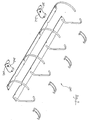
- FIG. 4 and 5 A second embodiment of a ring binder mechanism according to the present invention is shown in Figs. 4 and 5 and generally designated as 100.
- the basic structure of this ring binder mechanism 100 is very similar to that shown in Figs. 1 to 3B. However, it can be seen that, in this particular embodiment, there are three pairs of half-rings 102A, 102B mounted to a pair of plates 104. Three wires 106 are provided adjacent to the half-rings 102A, 102B.
- only two tabs 108 are provided and extend below the lower surfaces of the plates 104.
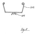
- Figs. 6 and 7 show a third embodiment of a ring binder mechanism according to the present invention as generally designated as 200.
- the basic structure of this mechanism 200 is very similar to those shown in Figs. 1 to 5.
- a major difference of this ring binder mechanism 200 is that each of tabs 202 includes a plurality of prongs 204 which are integrally formed with the tabs 202 (shown more clearly in Fig. 8). These prongs 204 can be pushed to penetrate into a cover (not shown), in order to secure the ring binder mechanism 200 to the cover.
- a housing extending over the entire length of the pivotal plates can be dispensed with, thus saving a significant amount of raw materials, hence reducing the cost of production and the ultimate price.
- the supporting members may be platelets extending over the upper surfaces of the plate members, and apertures may be provided on both the platelets and the plate members so that rivets may be engaged with the hole on the platelets for securing the ring binder mechanism to a cover.
Landscapes
- Sheet Holders (AREA)
Applications Claiming Priority (2)
| Application Number | Priority Date | Filing Date | Title |
|---|---|---|---|
| GB9811259 | 1998-05-26 | ||
| GBGB9811259.2A GB9811259D0 (en) | 1998-05-26 | 1998-05-26 | A ring binder mechanism |
Publications (2)
| Publication Number | Publication Date |
|---|---|
| EP0960746A2 true EP0960746A2 (fr) | 1999-12-01 |
| EP0960746A3 EP0960746A3 (fr) | 2000-03-29 |
Family
ID=10832700
Family Applications (1)
| Application Number | Title | Priority Date | Filing Date |
|---|---|---|---|
| EP99301947A Withdrawn EP0960746A3 (fr) | 1998-05-26 | 1999-03-15 | Mécanisme pour classeurs à anneaux |
Country Status (3)
| Country | Link |
|---|---|
| EP (1) | EP0960746A3 (fr) |
| CN (1) | CN1236710A (fr) |
| GB (1) | GB9811259D0 (fr) |
Cited By (1)
| Publication number | Priority date | Publication date | Assignee | Title |
|---|---|---|---|---|
| EP1203670A3 (fr) * | 2000-11-01 | 2003-08-20 | World Wide Stationery Manufacturing Co. Ltd. | Mécanisme pour classeurs à anneaux |
Family Cites Families (2)
| Publication number | Priority date | Publication date | Assignee | Title |
|---|---|---|---|---|
| US2377179A (en) * | 1943-09-29 | 1945-05-29 | Pitt William | Loose-leaf binder |
| FR2215812A5 (fr) * | 1973-01-29 | 1974-08-23 | Assant Henri |
-
1998
- 1998-05-26 GB GBGB9811259.2A patent/GB9811259D0/en not_active Ceased
-
1999
- 1999-03-15 EP EP99301947A patent/EP0960746A3/fr not_active Withdrawn
- 1999-05-14 CN CN 99107353 patent/CN1236710A/zh active Pending
Cited By (1)
| Publication number | Priority date | Publication date | Assignee | Title |
|---|---|---|---|---|
| EP1203670A3 (fr) * | 2000-11-01 | 2003-08-20 | World Wide Stationery Manufacturing Co. Ltd. | Mécanisme pour classeurs à anneaux |
Also Published As
| Publication number | Publication date |
|---|---|
| CN1236710A (zh) | 1999-12-01 |
| EP0960746A3 (fr) | 2000-03-29 |
| GB9811259D0 (en) | 1998-07-22 |
Similar Documents
| Publication | Publication Date | Title |
|---|---|---|
| US5971649A (en) | Ring binder mechanism | |
| EP0707981B1 (fr) | Mécanisme pour classeur à anneaux | |
| US5393155A (en) | Ring binder housing | |
| EP0764549A1 (fr) | Classeur à anneaux | |
| US20060228164A1 (en) | Ring binder mechanism | |
| CA2184666A1 (fr) | Reliure a anneau | |
| EP0151853B1 (fr) | Classeur à anneaux | |
| US6109813A (en) | Ring binder with divided housings | |
| CN101376309B (zh) | 具有塑胶材料壳体的环形夹机构 | |
| US8602672B2 (en) | Binding device | |
| CA2492755A1 (fr) | Mecanisme de reliure a anneaux | |
| EP0960746A2 (fr) | Mécanisme pour classeurs à anneaux | |
| NO171834B (no) | Anordning for oppstilling av ark forsynt med hull | |
| US4830528A (en) | Closure mechanism for a loose-leaf holder | |
| HK1040070A1 (zh) | 杠杆拱環型文件夾的鎖定裝置 | |
| AU2147399A (en) | Ring binder mechanism | |
| US5980146A (en) | Ring binder | |
| EP1065072A2 (fr) | Ringordnermechanismus | |
| GB2217772A (en) | End connector for watch band | |
| EP1203670A2 (fr) | Mécanisme pour classeurs à anneaux | |
| JP2008055909A (ja) | リングバインダ機構 | |
| US4832521A (en) | Closure mechanism for a loose-leaf holder | |
| GB2236280A (en) | Loose-leaf binder | |
| EP1319521A1 (fr) | Un boítier pour un mécanisme à anneaux d'une reliure de feuilles volantes et la reliure de feuilles volantes | |
| US4264228A (en) | Composite looseleaf mechanism |
Legal Events
| Date | Code | Title | Description |
|---|---|---|---|
| PUAI | Public reference made under article 153(3) epc to a published international application that has entered the european phase |
Free format text: ORIGINAL CODE: 0009012 |
|
| AK | Designated contracting states |
Kind code of ref document: A2 Designated state(s): AT BE CH CY DE DK ES FI FR GB GR IE IT LI LU MC NL PT SE |
|
| AX | Request for extension of the european patent |
Free format text: AL;LT;LV;MK;RO;SI |
|
| PUAL | Search report despatched |
Free format text: ORIGINAL CODE: 0009013 |
|
| AK | Designated contracting states |
Kind code of ref document: A3 Designated state(s): AT BE CH CY DE DK ES FI FR GB GR IE IT LI LU MC NL PT SE |
|
| AX | Request for extension of the european patent |
Free format text: AL;LT;LV;MK;RO;SI |
|
| AKX | Designation fees paid | ||
| REG | Reference to a national code |
Ref country code: DE Ref legal event code: 8566 |
|
| STAA | Information on the status of an ep patent application or granted ep patent |
Free format text: STATUS: THE APPLICATION IS DEEMED TO BE WITHDRAWN |
|
| 18D | Application deemed to be withdrawn |
Effective date: 20000930 |