EP0960785A2 - Schutzstruktur für einen Insassen - Google Patents
Schutzstruktur für einen Insassen Download PDFInfo
- Publication number
- EP0960785A2 EP0960785A2 EP99303822A EP99303822A EP0960785A2 EP 0960785 A2 EP0960785 A2 EP 0960785A2 EP 99303822 A EP99303822 A EP 99303822A EP 99303822 A EP99303822 A EP 99303822A EP 0960785 A2 EP0960785 A2 EP 0960785A2
- Authority
- EP
- European Patent Office
- Prior art keywords
- knee guard
- brackets
- closure member
- glove box
- vehicle
- Prior art date
- Legal status (The legal status is an assumption and is not a legal conclusion. Google has not performed a legal analysis and makes no representation as to the accuracy of the status listed.)
- Granted
Links
- 210000003127 knee Anatomy 0.000 claims abstract description 66
- 230000002787 reinforcement Effects 0.000 claims abstract description 8
- 235000010627 Phaseolus vulgaris Nutrition 0.000 description 1
- 244000046052 Phaseolus vulgaris Species 0.000 description 1
- 239000006185 dispersion Substances 0.000 description 1
- 238000012986 modification Methods 0.000 description 1
- 230000004048 modification Effects 0.000 description 1
- 230000035939 shock Effects 0.000 description 1
- 238000003466 welding Methods 0.000 description 1
Images

Classifications
-
- B—PERFORMING OPERATIONS; TRANSPORTING
- B60—VEHICLES IN GENERAL
- B60R—VEHICLES, VEHICLE FITTINGS, OR VEHICLE PARTS, NOT OTHERWISE PROVIDED FOR
- B60R21/00—Arrangements or fittings on vehicles for protecting or preventing injuries to occupants or pedestrians in case of accidents or other traffic risks
- B60R21/02—Occupant safety arrangements or fittings, e.g. crash pads
- B60R21/04—Padded linings for the vehicle interior ; Energy absorbing structures associated with padded or non-padded linings
- B60R21/045—Padded linings for the vehicle interior ; Energy absorbing structures associated with padded or non-padded linings associated with the instrument panel or dashboard
-
- B—PERFORMING OPERATIONS; TRANSPORTING
- B60—VEHICLES IN GENERAL
- B60R—VEHICLES, VEHICLE FITTINGS, OR VEHICLE PARTS, NOT OTHERWISE PROVIDED FOR
- B60R7/00—Stowing or holding appliances inside vehicle primarily intended for personal property smaller than suit-cases, e.g. travelling articles, or maps
- B60R7/04—Stowing or holding appliances inside vehicle primarily intended for personal property smaller than suit-cases, e.g. travelling articles, or maps in driver or passenger space, e.g. using racks
- B60R7/06—Stowing or holding appliances inside vehicle primarily intended for personal property smaller than suit-cases, e.g. travelling articles, or maps in driver or passenger space, e.g. using racks mounted on or below dashboards
-
- B—PERFORMING OPERATIONS; TRANSPORTING
- B60—VEHICLES IN GENERAL
- B60R—VEHICLES, VEHICLE FITTINGS, OR VEHICLE PARTS, NOT OTHERWISE PROVIDED FOR
- B60R21/00—Arrangements or fittings on vehicles for protecting or preventing injuries to occupants or pedestrians in case of accidents or other traffic risks
- B60R2021/003—Arrangements or fittings on vehicles for protecting or preventing injuries to occupants or pedestrians in case of accidents or other traffic risks characterised by occupant or pedestian
- B60R2021/0039—Body parts of the occupant or pedestrian affected by the accident
- B60R2021/0051—Knees
-
- B—PERFORMING OPERATIONS; TRANSPORTING
- B60—VEHICLES IN GENERAL
- B60R—VEHICLES, VEHICLE FITTINGS, OR VEHICLE PARTS, NOT OTHERWISE PROVIDED FOR
- B60R21/00—Arrangements or fittings on vehicles for protecting or preventing injuries to occupants or pedestrians in case of accidents or other traffic risks
- B60R21/02—Occupant safety arrangements or fittings, e.g. crash pads
- B60R21/16—Inflatable occupant restraints or confinements designed to inflate upon impact or impending impact, e.g. air bags
- B60R21/20—Arrangements for storing inflatable members in their non-use or deflated condition; Arrangement or mounting of air bag modules or components
- B60R21/205—Arrangements for storing inflatable members in their non-use or deflated condition; Arrangement or mounting of air bag modules or components in dashboards
Definitions
- the present invention relates to an occupant protection structure for a motor vehicle and more particularly to a knee guard structure for protecting knees of an occupant at the event of a collision.
- the knee guard structure supports the knees of the occupant to prevent the occupant from getting in under the instrument panel.
- An example of the knee guard structure is disclosed in Japanese Patent Application Laid-open No. Toku-Kai-Hei 7-2035.
- the knee guard is provided at the lower part of the instrument panel so as to be located opposite to the knees of an occupant seated.
- a glove box at the lower part of the instrument panel.
- a knee guard bracket is disposed on both ends of the glove box, respectively and a connecting member interconnects between both brackets.
- the knees of the passenger has a contact with a lid of the glove box and an impact load is inputted to the left and right knee guard brackets through the lid.
- the knees of the passenger do not always abut against the knee guard orthogonally. Especially, at the event of an offset collision or an oblique collision, the knees abut against the knee guard partially or in the diagonal direction.
- the knees of the passenger abut against the left and right brackets through the lid of the glove box, since these brackets are disposed apart from each other, it is difficult to transfer the impact load received from the lid of the glove box uniformly to the brackets. That is, an impact energy is difficult to be absorbed efficiently.
- the knee guard structure comprises left and right knee guard brackets secured to a steering support beam with a glove box between, a connecting member transversely connecting the left and right knee guard brackets, a closure member of the glove box composed of an outer panel and an inner panel and disposed adjacent to the left and right knee guard brackets and a reinforcement provided between the inner and outer panels and having a closed cross section extended in the widthwise direction of the vehicle up to left and right end portions of the closure member.
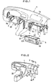
- reference numeral denotes an instrument panel, in which a steering support beam 2 for supporting a steering column (not shown) is disposed in the widthwise direction of a vehicle.
- the steering support beam 2 is connected at both ends thereof with a left and right front pillar (not shown) through a bracket 2a, respectively. Further, the steering support beam 2 is connected on the driver side thereof with a pair of left and right knee guard brackets 3 and is connected on the passenger side thereof with a pair of left and right knee guard brackets 4.
- knee guard brackets 3, 4 have a U-shaped or C-shaped cross section and load inputting surfaces 3a, 4a, respectively, being connected by welding at the front end thereof with the steering support beam 2 so as to be located opposite to the knees of occupants seated on a driver's seat and a passenger's seat.
- the left and right knee guard brackets 3, 3 on the driver side including the load inputting surfaces 3a, 3a are covered with the lower part of the instrument panel 1.
- the lower part of instrument panel 1 may be replaced with a knee pad member and the like, thus a knee guard 30 on the driver side being formed.
- the left and right knee guard brackets 4, 4 on the passenger side are disposed respectively along the left and right sides of a glove box which will be described hereinafter.
- a closure member 61 of a glove box 6 has left and right flange sections 61f, 61f at left and right ends thereof and the left and right flange sections 61f, 61f are opposed adjacent to the left and right load inputting surfaces 4a, 4a, respectively.
- a connecting member 5 fabricated of a pipe member connects the left and right knee guard brackets 4, 4 with each other. The connecting member 5 is disposed above the glove box 6 in a position not disturbing the closure and opening of the glove box 6. Further, as illustrated in Fig.
- a knee guard 40 on the passenger side is constituted by the pair of the knee guard brackets 4, 4, the closure member 61 of the glove box 6 and the connecting member 5.
- the glove box 6 includes the closure member 61 and a box member 62 and the left and right flange sections 61f, 61f are formed in a state of laterally overhanging from the box member 62.
- the glove box 6 is housed in a hollow provided under the instrument panel 1 on the passenger side and is hingedly connected to a pivot 63 so as to enable the closure and opening thereof.
- the closure member 61 of the glove box 6 is constituted by an inner panel 61a and an outer panel 61b with a reinforcement 61c inside.
- the reinforcement has at least one closed cross section 61d extending laterally to the left and right flange sections 61f, 61f which are opposite adjacent to the load inputting surfaces 4a, 4a of the knee guard brackets 4, 4.
- the load inputting surface 4a is formed into a configuration substantially agreeing with the front configuration of the flange section 61f and has a vertical length approximately equal to that of the reinforcement 61c.
- Reference numeral 61e denotes a lock mechanism provided in the center of the closure member 61.
- an air bag system 7 in an opening 1b of the instrument panel 1 on the passenger side and it is mounted on the steering support beam 2 through a bracket.
- an impact sensor (not shown) detects an impact, an air bag built in the air bag system 7 inflates and pushes to open a lid of the opening 1b. Since the operation of the air bag after deployment is well known, further detailed description is omitted.
- a vehicle driver When a head-on impact occurs, a vehicle driver abuts against the knee guard 30 on the driver seat at his or her knees and the knee guard brackets 3, 3 are subjected to the buckling deformation. During the deformation, the impact load is dispersively transmitted to the steering support beam and other vehicle body members to be absorbed therein. On the other hand, the head of the vehicle driver is held by the air bag coming on toward him or her.
- a passenger abuts against the closure member 61 of the glove box 6 at his or her knees and the left and right flange sections 61f, 61f contact the load inputting surfaces 4a, 4a of the knee guard brackets 4, 4.
- an impact load is inputted from the closure member 61 to the left and right knee guard brackets 4, 4.
- the knee guard brackets 4, 4 are subjected to the buckling deformation to absorb the impact load.
- the air bag system 7 is deployed and the coming on air bag holds the head of the passenger.
- the closure member 61 conveys the impact load uniformly to the left and right load inputting surfaces 4a, 4a without having a large deformation.
- the impact load inputted to the closure member 61 is surely transmitted to the left and right knee guard brackets 4, 4.
- the left and right knee guard brackets 4, 4 are rigidly connected with each other by the connecting member 5, these brackets can be prevented from being deformed largely in the widthwise direction of the vehicle.
- the impact load is dispersively transmitted from the knee guard brackets 4, 4 to the steering support bean 2 and other body members.
- the load inputting surface 4a is formed into a configuration substantially agreeing with the front configuration of the flange section 61f, the impact load is uniformly transmitted to the knee guard bracket 4, 4.
- the deformation of the closed cross section 61d absorbs the whole impact load without dispersion to other body members.
Landscapes
- Engineering & Computer Science (AREA)
- Mechanical Engineering (AREA)
- Vehicle Step Arrangements And Article Storage (AREA)
- Body Structure For Vehicles (AREA)
- Air Bags (AREA)
- Instrument Panels (AREA)
Applications Claiming Priority (2)
| Application Number | Priority Date | Filing Date | Title |
|---|---|---|---|
| JP15208698 | 1998-05-15 | ||
| JP15208698A JP3893218B2 (ja) | 1998-05-15 | 1998-05-15 | 車両の乗員保護構造 |
Publications (3)
| Publication Number | Publication Date |
|---|---|
| EP0960785A2 true EP0960785A2 (de) | 1999-12-01 |
| EP0960785A3 EP0960785A3 (de) | 2003-01-08 |
| EP0960785B1 EP0960785B1 (de) | 2005-07-20 |
Family
ID=15532749
Family Applications (1)
| Application Number | Title | Priority Date | Filing Date |
|---|---|---|---|
| EP99303822A Expired - Lifetime EP0960785B1 (de) | 1998-05-15 | 1999-05-17 | Schutzstruktur für einen Insassen |
Country Status (4)
| Country | Link |
|---|---|
| US (1) | US6299208B1 (de) |
| EP (1) | EP0960785B1 (de) |
| JP (1) | JP3893218B2 (de) |
| DE (1) | DE69926177T2 (de) |
Cited By (12)
| Publication number | Priority date | Publication date | Assignee | Title |
|---|---|---|---|---|
| WO2001074627A1 (en) * | 2000-03-31 | 2001-10-11 | Delphi Technologies, Inc. | Structural beam with integrated knee energy absorbers |
| US6497432B2 (en) | 2000-02-22 | 2002-12-24 | Delphi Technologies, Inc. | Structural attachment system and method for a vehicle |
| US6497775B2 (en) | 2001-04-11 | 2002-12-24 | Delphi Technologies, Inc. | Method and apparatus for manufacturing a vehicle cross car beam or other structural, functional articles out of multiple materials with optimum material utilization |
| US6517114B1 (en) | 2000-02-22 | 2003-02-11 | Delphi Technologies Inc | Steering column structural support system and method |
| US6520849B1 (en) | 2000-03-31 | 2003-02-18 | Delphi Technologies, Inc. | Integrated structural HVAC system |
| WO2003057532A3 (en) * | 2002-01-04 | 2003-10-09 | Johnson Controls Tech Co | Article attachment system |
| US6648402B2 (en) | 2000-02-22 | 2003-11-18 | Delphi Technologies, Inc. | Structural support brace |
| US6827384B2 (en) | 2001-05-01 | 2004-12-07 | Johnson Controls Technology Company | Modular system for a vehicle |
| FR2862268A1 (fr) | 2003-11-17 | 2005-05-20 | Faurecia Interieur Ind | Planche de bord a partie inferieure mobile en cas de choc et vehicule automobile correspondant |
| FR2914890A1 (fr) * | 2007-04-12 | 2008-10-17 | Faurecia Interieur Ind Snc | Amortisseur de genoux pour vehicule automobile |
| EP2098416A1 (de) * | 2008-03-07 | 2009-09-09 | Delphi Technologies, Inc. | Armaturentafel-Baugruppe |
| DE102011010255B4 (de) * | 2010-01-29 | 2014-01-09 | Suzuki Motor Corporation | Instrumententafel |
Families Citing this family (29)
| Publication number | Priority date | Publication date | Assignee | Title |
|---|---|---|---|---|
| JP2002326550A (ja) * | 2001-05-07 | 2002-11-12 | Isuzu Motors Ltd | ニーボルスター |
| US6869123B2 (en) * | 2001-11-26 | 2005-03-22 | General Electric Company | Instrument panel thermoplastic energy absorbers |
| US6837518B2 (en) * | 2002-08-23 | 2005-01-04 | L&W Engineering Incorporated | Reinforcement structure for instrument panel |
| JP3981826B2 (ja) * | 2002-12-25 | 2007-09-26 | 三菱自動車工業株式会社 | 乗員保護装置 |
| US6921128B2 (en) * | 2003-05-06 | 2005-07-26 | Lear Corporation | Universal energy absorbing bracket |
| JP3994913B2 (ja) * | 2003-05-16 | 2007-10-24 | 日産自動車株式会社 | 車両用収納ボックスの取付構造 |
| US7311328B2 (en) * | 2003-09-05 | 2007-12-25 | Salflex Polymers Ltd. | Instrument panel subassembly including a glove box door |
| US20050071988A1 (en) * | 2003-10-06 | 2005-04-07 | Jeff Owel | Apparatus for fastening weld fasteners to a structure |
| US7204515B2 (en) | 2004-03-09 | 2007-04-17 | Toyota Technical Center Usa, Inc. | Occupant restraint mechanism |
| KR100551835B1 (ko) * | 2004-07-20 | 2006-02-13 | 현대자동차주식회사 | 자동차용 니 볼스트 브래킷 구조 |
| DE102004055654B4 (de) * | 2004-11-15 | 2007-11-29 | Faurecia Innenraum Systeme Gmbh | Staufachvorrichtung |
| US20060232055A1 (en) * | 2005-04-15 | 2006-10-19 | Visteon Global Technologies, Inc. | Energy absorbing structure |
| US7708313B2 (en) * | 2005-09-01 | 2010-05-04 | International Automotive Components Group North America, Inc. | Plastic basket countermeasure for door side impact |
| US7874587B2 (en) * | 2006-02-07 | 2011-01-25 | Toyota Motor Engineering & Manufacturing North America, Inc. | Glove box assembly exhibiting knee impact force transferring structure with respect to an associated vehicle dash/instrument panel and reinforcing bar and including removable strengthening ribs for tuning of crash safety characteristics |
| US7484792B2 (en) * | 2006-02-07 | 2009-02-03 | Toyota Motor Engineering & Manufacturing North America, Inc. | Glove box assembly exhibiting knee impact force transferring structure with respect to an associated vehicle dash/instrument panel and reinforcing bar |
| DE602006013286D1 (de) * | 2006-05-16 | 2010-05-12 | Ford Global Tech Llc | Sicherheitseinrictung |
| JP4916411B2 (ja) * | 2007-10-04 | 2012-04-11 | 本田技研工業株式会社 | 車両の収納装置 |
| US7651144B2 (en) * | 2007-11-27 | 2010-01-26 | Clark Rubber & Plastic Company | Seal water catch for recreational vehicle |
| US7703829B2 (en) * | 2008-01-11 | 2010-04-27 | Toyota Motor Engineering & Manufacturing North America, Inc. | Instrument panel energy transferring system |
| US20100148531A1 (en) * | 2008-09-12 | 2010-06-17 | Evans Gregg S | Automotive glove box hinge mechanism |
| US8251399B2 (en) * | 2009-11-24 | 2012-08-28 | Toyota Motor Engineering & Manufacturing North America, Inc. | Instrument panel energy absorption systems |
| JP5498921B2 (ja) * | 2010-11-22 | 2014-05-21 | 本田技研工業株式会社 | 車両用グローブボックス構造 |
| US8491037B2 (en) * | 2011-08-09 | 2013-07-23 | Ford Global Technologies, Llc | Extend and breakaway bracket for glove box |
| WO2014028753A1 (en) * | 2012-08-15 | 2014-02-20 | Spartan Motors, Inc. | Break away dash panel |
| JP6065525B2 (ja) * | 2012-11-06 | 2017-01-25 | 三菱自動車工業株式会社 | 車両の膝衝突保護構造 |
| US9302414B2 (en) * | 2014-06-24 | 2016-04-05 | Ford Global Technologies | Molded active plastics components for a vehicle airbag assembly |
| US9457755B2 (en) * | 2015-01-09 | 2016-10-04 | Toyota Motor Engineering & Manufacturing North America, Inc. | One piece instrument panel with molded upper bin |
| KR101806707B1 (ko) | 2016-06-09 | 2017-12-07 | 현대자동차주식회사 | 차량용 글로브 박스의 니 볼스터 장치 |
| CN111252007A (zh) | 2018-12-03 | 2020-06-09 | 福特全球技术公司 | 用于在仪表板中安装中心堆叠模块的支架 |
Citations (1)
| Publication number | Priority date | Publication date | Assignee | Title |
|---|---|---|---|---|
| JPH072035A (ja) | 1992-12-15 | 1995-01-06 | Mazda Motor Corp | 自動車の乗員保護装置 |
Family Cites Families (14)
| Publication number | Priority date | Publication date | Assignee | Title |
|---|---|---|---|---|
| FR2447301A1 (fr) * | 1979-01-23 | 1980-08-22 | Renault | Dispositif de protection des occupants d'un vehicule automobile |
| JPS61207252A (ja) * | 1985-03-12 | 1986-09-13 | Mazda Motor Corp | 自動車のニ−プロテクタ |
| US4709943A (en) * | 1985-07-17 | 1987-12-01 | Mazda Motor Corporation | Knee protector structure for vehicle |
| US4978136A (en) * | 1988-12-19 | 1990-12-18 | Mazda Motor Corporation | Automotive knee protector |
| US5230530A (en) * | 1989-01-09 | 1993-07-27 | Mazda Motor Corporation | Air bag mount structure for vehicle |
| JP2511074Y2 (ja) * | 1989-07-24 | 1996-09-18 | 本田技研工業株式会社 | ニ―ボルスタ― |
| JPH0463745A (ja) * | 1990-07-04 | 1992-02-28 | Mazda Motor Corp | 車両用グローブボックス装置 |
| JPH0713612A (ja) | 1993-06-25 | 1995-01-17 | Hitachi Eng Co Ltd | 制御システムのシミュレーション装置 |
| US5413379A (en) * | 1993-09-16 | 1995-05-09 | Honda Giken Kogyo Kabushiki Kaisha | Knee bolster structure |
| JP3185627B2 (ja) * | 1995-09-26 | 2001-07-11 | 三菱自動車工業株式会社 | グローブボックス構造 |
| DE19548712C1 (de) * | 1995-12-23 | 1997-01-30 | Daimler Benz Ag | Knieschutz in einem Kraftwagen mit einem Lastverteiler |
| JP3475694B2 (ja) * | 1997-01-31 | 2003-12-08 | いすゞ自動車株式会社 | ニーボルスタ構造 |
| US5951045A (en) * | 1997-03-26 | 1999-09-14 | A B Volvo | Knee protection system for a vehicle |
| JP3724765B2 (ja) * | 1997-11-26 | 2005-12-07 | 富士重工業株式会社 | インストルメントパネル構造 |
-
1998
- 1998-05-15 JP JP15208698A patent/JP3893218B2/ja not_active Expired - Fee Related
-
1999
- 1999-05-17 US US09/312,606 patent/US6299208B1/en not_active Expired - Fee Related
- 1999-05-17 DE DE69926177T patent/DE69926177T2/de not_active Expired - Lifetime
- 1999-05-17 EP EP99303822A patent/EP0960785B1/de not_active Expired - Lifetime
Patent Citations (1)
| Publication number | Priority date | Publication date | Assignee | Title |
|---|---|---|---|---|
| JPH072035A (ja) | 1992-12-15 | 1995-01-06 | Mazda Motor Corp | 自動車の乗員保護装置 |
Cited By (16)
| Publication number | Priority date | Publication date | Assignee | Title |
|---|---|---|---|---|
| US6648402B2 (en) | 2000-02-22 | 2003-11-18 | Delphi Technologies, Inc. | Structural support brace |
| US6497432B2 (en) | 2000-02-22 | 2002-12-24 | Delphi Technologies, Inc. | Structural attachment system and method for a vehicle |
| US6517114B1 (en) | 2000-02-22 | 2003-02-11 | Delphi Technologies Inc | Steering column structural support system and method |
| US6520849B1 (en) | 2000-03-31 | 2003-02-18 | Delphi Technologies, Inc. | Integrated structural HVAC system |
| WO2001074627A1 (en) * | 2000-03-31 | 2001-10-11 | Delphi Technologies, Inc. | Structural beam with integrated knee energy absorbers |
| US6497775B2 (en) | 2001-04-11 | 2002-12-24 | Delphi Technologies, Inc. | Method and apparatus for manufacturing a vehicle cross car beam or other structural, functional articles out of multiple materials with optimum material utilization |
| US6827384B2 (en) | 2001-05-01 | 2004-12-07 | Johnson Controls Technology Company | Modular system for a vehicle |
| US6789832B2 (en) | 2002-01-04 | 2004-09-14 | Johnson Controls Technology Company | Article attachment system |
| WO2003057532A3 (en) * | 2002-01-04 | 2003-10-09 | Johnson Controls Tech Co | Article attachment system |
| FR2862268A1 (fr) | 2003-11-17 | 2005-05-20 | Faurecia Interieur Ind | Planche de bord a partie inferieure mobile en cas de choc et vehicule automobile correspondant |
| WO2005049388A1 (fr) | 2003-11-17 | 2005-06-02 | Faurecia Interieur Industrie | Planche de bord a partie inferieure mobile en cas de choc et vehicule automobile correspondant |
| FR2914890A1 (fr) * | 2007-04-12 | 2008-10-17 | Faurecia Interieur Ind Snc | Amortisseur de genoux pour vehicule automobile |
| WO2008142328A1 (fr) * | 2007-04-12 | 2008-11-27 | Faurecia Interieur Industrie | Amortisseur de genoux pour véhicule automobile |
| EP2098416A1 (de) * | 2008-03-07 | 2009-09-09 | Delphi Technologies, Inc. | Armaturentafel-Baugruppe |
| DE102011010255B4 (de) * | 2010-01-29 | 2014-01-09 | Suzuki Motor Corporation | Instrumententafel |
| US8714614B2 (en) | 2010-01-29 | 2014-05-06 | Suzuki Motor Corporation | Instrument panel |
Also Published As
| Publication number | Publication date |
|---|---|
| DE69926177T2 (de) | 2006-04-27 |
| DE69926177D1 (de) | 2005-08-25 |
| EP0960785B1 (de) | 2005-07-20 |
| US6299208B1 (en) | 2001-10-09 |
| EP0960785A3 (de) | 2003-01-08 |
| JPH11321501A (ja) | 1999-11-24 |
| JP3893218B2 (ja) | 2007-03-14 |
Similar Documents
| Publication | Publication Date | Title |
|---|---|---|
| EP0960785B1 (de) | Schutzstruktur für einen Insassen | |
| US5348342A (en) | Air bag system for side collision protection | |
| US5037130A (en) | Knee protector for automotive vehicles | |
| JP3043506B2 (ja) | 自動車の乗員保護装置 | |
| JPH09104317A (ja) | 乗員保護装置 | |
| KR20030003267A (ko) | 차량용 탑승자 보호장치 | |
| US4946192A (en) | Knee protector | |
| JPH03547A (ja) | 自動車乗員用安全装置 | |
| JP2891287B2 (ja) | 車両用シート | |
| JPH05188077A (ja) | サイドエアバッグ装置の衝突センサ配置構造 | |
| JP2703310B2 (ja) | 自動車のコラムカバー構造 | |
| JP3105348B2 (ja) | 自動車のニープロテクタ構造 | |
| JP2891286B2 (ja) | 車両用シート | |
| JPH07267038A (ja) | 車両用安全シート | |
| KR20240099877A (ko) | 자동차의 파 사이드 에어백 장치 | |
| JP3531188B2 (ja) | 車両のステアリングシャフト支持構造 | |
| JPH07179162A (ja) | 自動車における内装品のエネルギー吸収構造 | |
| JP3096298B2 (ja) | 自動車のエアバッグ配設構造 | |
| JP2576582Y2 (ja) | 自動車のエアバッグ装置 | |
| KR200147871Y1 (ko) | 사이드 에어백 장착 가능한 자동차 시이트 프레임 | |
| JP3337516B2 (ja) | 自動車の乗員保護装置 | |
| KR100336363B1 (ko) | 차량용 에어백 하우징 | |
| WO2002024490A1 (en) | Protective arrangement in a motor vehicle | |
| KR100222352B1 (ko) | 자동차 전방측면 충돌시 운전석 무릎 보호장치 | |
| KR100410844B1 (ko) | 자동차의 커튼 에어백 장치 |
Legal Events
| Date | Code | Title | Description |
|---|---|---|---|
| PUAI | Public reference made under article 153(3) epc to a published international application that has entered the european phase |
Free format text: ORIGINAL CODE: 0009012 |
|
| AK | Designated contracting states |
Kind code of ref document: A2 Designated state(s): AT BE CH CY DE DK ES FI FR GB GR IE IT LI LU MC NL PT SE |
|
| AX | Request for extension of the european patent |
Free format text: AL;LT;LV;MK;RO;SI |
|
| PUAL | Search report despatched |
Free format text: ORIGINAL CODE: 0009013 |
|
| AK | Designated contracting states |
Kind code of ref document: A3 Designated state(s): AT BE CH CY DE DK ES FI FR GB GR IE IT LI LU MC NL PT SE |
|
| AX | Request for extension of the european patent |
Free format text: AL;LT;LV;MK;RO;SI |
|
| 17P | Request for examination filed |
Effective date: 20030409 |
|
| 17Q | First examination report despatched |
Effective date: 20030627 |
|
| AKX | Designation fees paid |
Designated state(s): DE GB |
|
| GRAP | Despatch of communication of intention to grant a patent |
Free format text: ORIGINAL CODE: EPIDOSNIGR1 |
|
| GRAS | Grant fee paid |
Free format text: ORIGINAL CODE: EPIDOSNIGR3 |
|
| GRAA | (expected) grant |
Free format text: ORIGINAL CODE: 0009210 |
|
| AK | Designated contracting states |
Kind code of ref document: B1 Designated state(s): DE GB |
|
| REG | Reference to a national code |
Ref country code: GB Ref legal event code: FG4D |
|
| REF | Corresponds to: |
Ref document number: 69926177 Country of ref document: DE Date of ref document: 20050825 Kind code of ref document: P |
|
| PG25 | Lapsed in a contracting state [announced via postgrant information from national office to epo] |
Ref country code: GB Free format text: LAPSE BECAUSE OF NON-PAYMENT OF DUE FEES Effective date: 20060517 |
|
| PLBE | No opposition filed within time limit |
Free format text: ORIGINAL CODE: 0009261 |
|
| STAA | Information on the status of an ep patent application or granted ep patent |
Free format text: STATUS: NO OPPOSITION FILED WITHIN TIME LIMIT |
|
| 26N | No opposition filed |
Effective date: 20060421 |
|
| GBPC | Gb: european patent ceased through non-payment of renewal fee |
Effective date: 20060517 |
|
| PGFP | Annual fee paid to national office [announced via postgrant information from national office to epo] |
Ref country code: DE Payment date: 20150512 Year of fee payment: 17 |
|
| REG | Reference to a national code |
Ref country code: DE Ref legal event code: R119 Ref document number: 69926177 Country of ref document: DE |
|
| PG25 | Lapsed in a contracting state [announced via postgrant information from national office to epo] |
Ref country code: DE Free format text: LAPSE BECAUSE OF NON-PAYMENT OF DUE FEES Effective date: 20161201 |