EP0960789B1 - Aufblasvorrichtung und Luftsackeinrichtung - Google Patents
Aufblasvorrichtung und Luftsackeinrichtung Download PDFInfo
- Publication number
- EP0960789B1 EP0960789B1 EP99109260A EP99109260A EP0960789B1 EP 0960789 B1 EP0960789 B1 EP 0960789B1 EP 99109260 A EP99109260 A EP 99109260A EP 99109260 A EP99109260 A EP 99109260A EP 0960789 B1 EP0960789 B1 EP 0960789B1
- Authority
- EP
- European Patent Office
- Prior art keywords
- casing
- chamber
- inflator
- longitudinal direction
- chambers
- Prior art date
- Legal status (The legal status is an assumption and is not a legal conclusion. Google has not performed a legal analysis and makes no representation as to the accuracy of the status listed.)
- Expired - Lifetime
Links
Images
Classifications
-
- B—PERFORMING OPERATIONS; TRANSPORTING
- B60—VEHICLES IN GENERAL
- B60R—VEHICLES, VEHICLE FITTINGS, OR VEHICLE PARTS, NOT OTHERWISE PROVIDED FOR
- B60R21/00—Arrangements or fittings on vehicles for protecting or preventing injuries to occupants or pedestrians in case of accidents or other traffic risks
- B60R21/02—Occupant safety arrangements or fittings, e.g. crash pads
- B60R21/16—Inflatable occupant restraints or confinements designed to inflate upon impact or impending impact, e.g. air bags
- B60R21/26—Inflatable occupant restraints or confinements designed to inflate upon impact or impending impact, e.g. air bags characterised by the inflation fluid source or means to control inflation fluid flow
-
- B—PERFORMING OPERATIONS; TRANSPORTING
- B60—VEHICLES IN GENERAL
- B60R—VEHICLES, VEHICLE FITTINGS, OR VEHICLE PARTS, NOT OTHERWISE PROVIDED FOR
- B60R21/00—Arrangements or fittings on vehicles for protecting or preventing injuries to occupants or pedestrians in case of accidents or other traffic risks
- B60R21/02—Occupant safety arrangements or fittings, e.g. crash pads
- B60R21/16—Inflatable occupant restraints or confinements designed to inflate upon impact or impending impact, e.g. air bags
- B60R21/26—Inflatable occupant restraints or confinements designed to inflate upon impact or impending impact, e.g. air bags characterised by the inflation fluid source or means to control inflation fluid flow
- B60R21/263—Inflatable occupant restraints or confinements designed to inflate upon impact or impending impact, e.g. air bags characterised by the inflation fluid source or means to control inflation fluid flow using a variable source, e.g. plural stage or controlled output
- B60R2021/2633—Inflatable occupant restraints or confinements designed to inflate upon impact or impending impact, e.g. air bags characterised by the inflation fluid source or means to control inflation fluid flow using a variable source, e.g. plural stage or controlled output with a plurality of inflation levels
-
- B—PERFORMING OPERATIONS; TRANSPORTING
- B60—VEHICLES IN GENERAL
- B60R—VEHICLES, VEHICLE FITTINGS, OR VEHICLE PARTS, NOT OTHERWISE PROVIDED FOR
- B60R21/00—Arrangements or fittings on vehicles for protecting or preventing injuries to occupants or pedestrians in case of accidents or other traffic risks
- B60R21/02—Occupant safety arrangements or fittings, e.g. crash pads
- B60R21/16—Inflatable occupant restraints or confinements designed to inflate upon impact or impending impact, e.g. air bags
- B60R21/20—Arrangements for storing inflatable members in their non-use or deflated condition; Arrangement or mounting of air bag modules or components
- B60R21/217—Inflation fluid source retainers, e.g. reaction canisters; Connection of bags, covers, diffusers or inflation fluid sources therewith or together
- B60R21/2171—Inflation fluid source retainers, e.g. reaction canisters; Connection of bags, covers, diffusers or inflation fluid sources therewith or together specially adapted for elongated cylindrical or bottle-like inflators with a symmetry axis perpendicular to the main direction of bag deployment, e.g. extruded reaction canisters
-
- B—PERFORMING OPERATIONS; TRANSPORTING
- B60—VEHICLES IN GENERAL
- B60R—VEHICLES, VEHICLE FITTINGS, OR VEHICLE PARTS, NOT OTHERWISE PROVIDED FOR
- B60R21/00—Arrangements or fittings on vehicles for protecting or preventing injuries to occupants or pedestrians in case of accidents or other traffic risks
- B60R21/02—Occupant safety arrangements or fittings, e.g. crash pads
- B60R21/16—Inflatable occupant restraints or confinements designed to inflate upon impact or impending impact, e.g. air bags
- B60R21/26—Inflatable occupant restraints or confinements designed to inflate upon impact or impending impact, e.g. air bags characterised by the inflation fluid source or means to control inflation fluid flow
- B60R21/264—Inflatable occupant restraints or confinements designed to inflate upon impact or impending impact, e.g. air bags characterised by the inflation fluid source or means to control inflation fluid flow using instantaneous generation of gas, e.g. pyrotechnic
- B60R21/2644—Inflatable occupant restraints or confinements designed to inflate upon impact or impending impact, e.g. air bags characterised by the inflation fluid source or means to control inflation fluid flow using instantaneous generation of gas, e.g. pyrotechnic using only solid reacting substances, e.g. pellets, powder
Definitions
- the present invention relates to an inflator for inflating an airbag which is installed in a vehicle including an automobile and, more particularly, to an inflator which generates gases in multiple stages.
- the present invention further relates to an airbag device having the inflator.
- An airbag device protects an occupant by an airbag which is inflated by gases generated by an inflator.
- Japanese patent publication 9-136604 discloses an inflator having a casing which is divided into two small combustion chambers, each of which is filled with gas generating agents. By igniting the two combustion chambers at different timings, the airbag is adjusted in its inflation speed and the inflation continuing time period. When a collision is made in small magnitude, only one of the combustion chambers is ignited.
- the inflator has the first combustion chamber disposed at one end side and the second chamber disposed at the other end side of the casing, and gas spout holes are formed in the respective middle portions in the longitudinal direction of the combustion chambers. Therefore, when gas spouts only from the first chamber, gas is introduced only from the one end side of the casing into the airbag so that a one-end-side portion of the airbag is inflated quickly and largely as compared to the other-end-side portion of the airbag.
- an inflator which corresponds to the preamble of claim 1 and 2 which comprises a casing which is divided into two chambers arranged in the longitudinal direction of the casing.
- the disclosed inflator comprises furthermore gas generant for generating gas filled in the chambers and gas spout holes formed in the casing, wherein the gas spout holes are disposed close to the middle in the longitudinal direction of the casing.
- the EP 0 792 776 discloses a hybrid inflator comprising two different sized chambers containing pressurized gas.
- the first chamber contains a gas generating material and an ignition device for a projectile for the rupture of a first burst disc closing an outlet of the first chamber.
- the second chamber only contains pressurized gas and a heating device and is closed by a second burst disc.
- the openings of both chambers lead to a common space between the two chambers which is surrounded by a cylinder connecting the two chambers and comprising gas outlets.
- This hybrid inflator has the disadvantage that the chambers have to be made of a strong material in order to keep the pressurized gas so that they have a high weight. Furthermore, there is the risk that in the case of a leakage the pressurized gas escapes rendering the inflator unusable.
- An inflator of the present invention has a cylindrical casing, at least one partition defining a plurality of chambers in the casing which are arranged in the longitudinal direction of the casing, gas generating agents filled in the chambers, and gas spout holes formed in the casing.
- the holes are disposed close to the middle in the longitudinal direction of the casing.
- An airbag device of the present invention has a container, an airbag folded and accommodated in the container, and the inflator of the present invention for inflating the airbag.
- the airbag device having the inflator as mentioned above, whether gas spouts from either of the chambers, the gas spouts from substantially the middle or the vicinity of the middle in the longitudinal direction of the casing of the inflator whereby the airbag is inflated into a bilaterally symmetrical configuration as a whole.
- the inside of the casing is divided into two chambers by the partition. Furthermore, the partition is disposed to be offset from the middle in the longitudinal direction of the casing to one end side of the casing so that the casing has a first chamber on the one end side and a second chamber on the other end side, and that the holes formed in the first chamber are disposed close to the partition and the holes formed in the second chamber are disposed about the middle in the longitudinal direction of the casing.
- the container has a configuration elongated in the longitudinal direction of the inflator, the partition of the inflator is disposed to be offset from the middle in the longitudinal direction of the container to one end side of the container, the holes formed in the first chamber on the one end side are disposed as close to the middle in the longitudinal direction of the container as possible, and that the holes formed in the second chamber on the other end side are disposed about the middle in the longitudinal direction of the container.
- the gas for inflating the airbag is generated by a gas generating agent, the casing need not to be very strong since the generated gas immediately can exit the chambers through a gas spout holes. Furthermore, the two chambers due to the different sizes have different inflating properties so that in case they are activated independently by increased number of different possibilities for controlling the inflating process of the airbag is obtained.
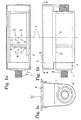
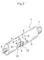
- An inflator 1 has a cylindrical casing 2, the inside of which is divided into two chambers, i.e. a first chamber 11 and a second chamber 12, by a partition 3.
- the casing 2 may be composed of an integral material from the left end to the right end in Figs. 1a, 1b and may be provided with the partition 3 inside thereof to form the first chamber and the second chamber.
- the casing 2 may comprise a first casing for the first chamber and a second casing for the second chamber which are integrally connected to each other.
- the casing 2 is made of metal such as aluminum or aluminum alloy.
- the partition 3 defining the first chamber and the second chamber is positioned to be offset from the middle in the longitudinal direction of casing 2 to the left side of Figs. 1a, 1b so that the first chamber 11 is smaller than the second chamber 12.
- the casing 2 is provided with gas spout holes 4 for allowing gas to spout from the chamber 11 and gas spout holes 5 for allowing gas to spout from the chamber 12.
- gas spout holes 4 for allowing gas to spout from the chamber 11
- gas spout holes 5 for allowing gas to spout from the chamber 12.
- the first chamber 11 positioned on the left side in the figure a plurality of the holes 4 formed therein are located as close to the partition 3 as possible.
- a plurality of the holes 5 formed therein are located about the middle of the longitudinal direction of the casing 2.
- Filled in the chambers 11, 12 are gas generant 21, 22 for generating gas, respectively.
- the chambers 11, 12 is provided with igniters 6, 7.
- the inflator 1 is disposed in a lower or rear portion of a container 8 in which the folded airbag 9 is accommodated.
- the top or front face of the container 8 is covered by a hd 10 (shown by two-dot chain lines in Fig. 1c).
- the container 8 is formed in a vessel-like configuration elongated in the longitudinal direction of the inflator 1.
- the holes 5 formed in the second chamber of the inflator 1 are disposed about the middle in the longitudinal direction of the container 8. Particularly according to this embodiment, the holes 5 are disposed symmetrically about the center line C of the container 8.
- the airbag device having the inflator 1 structured as mentioned above, whether gas spouts from either of the first chamber 11 and the second chamber 12, the gas spouting through the holes 4, 5 spouts out about the center of the airbag 9 whereby the airbag 9 is inflated into a laterally symmetrical configuration in front of the occupant.
- the airbag in case of inflating an airbag by using an inflator having two chambers, the airbag can be inflated into a laterally symmetrical configuration in front of an occupant. Particularly, even in case where gas spouts only from one chamber, the airbag can be inflated into a laterally symmetrical configuration.
Landscapes
- Physics & Mathematics (AREA)
- Fluid Mechanics (AREA)
- Engineering & Computer Science (AREA)
- Mechanical Engineering (AREA)
- Air Bags (AREA)
Claims (2)
- Aufblasvorrichtung (1), umfassend ein zylindrisches Gehäuse (2), einen Abschnitt (3), welcher zwei Kammern (11, 12) in dem Gehäuse (2) definiert, welche in der Längsrichtung des Gehäuses (2) angeordnet sind, in die Kammern (11, 12) gefüllte Gaserzeugungsmittel (21, 22) zum Erzeugen von Gas, und in dem Gehäuse (2) ausgebildete Gasaustrittslöcher (4, 5), wobei die Löcher (4, 5) in der Nähe der Mitte in der Längsrichtung des Gehäuses (2) angeordnet sind, und wobei das Innere des Gehäuses (2) in zwei Kammern (11, 12) aufgeteilt ist,
dadurch gekennzeichnet, dass der Abschnitt (3) versetzt von der Mitte in der Längsrichtung des Gehäuses (2) zu einer Endseite des Gehäuses (2) hin derart angeordnet ist, dass das Gehäuse (2) eine erste Kammer (11) auf der einen Endseite und eine zweite Kammer (12) auf der anderen Endseite besitzt, und
wobei die in der ersten Kammer (11) ausgebildeten Löcher (4) in der Nähe des Abschnittes (3) angeordnet sind und die in der zweiten Kammer (12) ausgebildeten Löcher (5) um die Mitte in der Längsrichtung des Gehäuses (2) angeordnet sind. - Airbag-Vorrichtung mit einem Behälter (8), mit einem gefalteten und in dem Behälter (8) aufgenommenen Airbag (9), und mit einer Aufblasvorrichtung (1) zum Aufblasen des Airbags (9), wobei die Aufblasvorrichtung (1) ein zylindrisches Gehäuse (2), einen Abschnitt (3), welcher zwei Kammern (11, 12) in dem Gehäuse (2) definiert, welche in der Längsrichtung des Gehäuses (2) angeordnet sind, in die Kammern (11, 12) gefüllte Gaserzeugungsmittel (21, 22) zum Erzeugen von Gas, und in der Nähe der Mitte der Längsrichtung des Gehäuses (2) in dem Gehäuse (2) ausgebildete Gasaustrittlöcher (4, 5) besitzt,
wobei das Innere des Gehäuses (2) der Aufblasvorrichtung (1) in zwei Kammern (11, 12) geteilt ist: eine erste Kammer (11) und eine zweite Kammer (12),
dadurch gekennzeichnet, dass der Behälter (8) eine in der Längsrichtung der Aufblasvorrichtung (1) verlängerte Form besitzt, wobei der Abschnitt (3) der Aufblasvorrichtung versetzt von der Mitte in der Längsrichtung des Behälters (8) zu einer Endseite des Behälters (8) hin angeordnet ist, wobei die in der ersten Kammer (11) an der einen Endseite ausgebildeten Löcher (4) in der Nähe des Abschnittes (3) angeordnet sind, und wobei die in der zweiten Kammer (12) angeordneten Löcher (5) auf der anderen Endseite um die Mitte in der Längsrichtung des Behälters (8) angeordnet sind.
Applications Claiming Priority (2)
| Application Number | Priority Date | Filing Date | Title |
|---|---|---|---|
| JP10149534A JPH11334518A (ja) | 1998-05-29 | 1998-05-29 | インフレータ及びエアバッグ装置 |
| JP14953498 | 1998-05-29 |
Publications (2)
| Publication Number | Publication Date |
|---|---|
| EP0960789A1 EP0960789A1 (de) | 1999-12-01 |
| EP0960789B1 true EP0960789B1 (de) | 2003-12-03 |
Family
ID=15477249
Family Applications (1)
| Application Number | Title | Priority Date | Filing Date |
|---|---|---|---|
| EP99109260A Expired - Lifetime EP0960789B1 (de) | 1998-05-29 | 1999-05-26 | Aufblasvorrichtung und Luftsackeinrichtung |
Country Status (4)
| Country | Link |
|---|---|
| US (1) | US6435551B1 (de) |
| EP (1) | EP0960789B1 (de) |
| JP (1) | JPH11334518A (de) |
| DE (1) | DE69913244T2 (de) |
Cited By (1)
| Publication number | Priority date | Publication date | Assignee | Title |
|---|---|---|---|---|
| US7325828B2 (en) | 2004-11-04 | 2008-02-05 | Daicel Chemical Industries, Ltd. | Multi-stage gas generator |
Families Citing this family (1)
| Publication number | Priority date | Publication date | Assignee | Title |
|---|---|---|---|---|
| US20050189755A1 (en) * | 2004-02-23 | 2005-09-01 | Kenji Numoto | Gas generator for air bag |
Family Cites Families (12)
| Publication number | Priority date | Publication date | Assignee | Title |
|---|---|---|---|---|
| DE2330194C3 (de) | 1973-06-14 | 1978-07-06 | Bayern-Chemie Gesellschaft Fuer Flugchemische Antriebe Mbh, 8261 Aschau | Gaszuführeinheit einer Aufprallschutzvorrichtung für Kraftfahrzeuginsassen |
| US4950458A (en) * | 1989-06-22 | 1990-08-21 | Morton International, Inc. | Passenger automotive restraint generator |
| US5033390A (en) * | 1989-11-13 | 1991-07-23 | Morton International, Inc. | Trilevel performance gas generator |
| US5219178A (en) * | 1990-10-08 | 1993-06-15 | Nippon Koki Co., Ltd. | Air bag inflation gas generator |
| US5564743A (en) * | 1995-03-22 | 1996-10-15 | Morton International, Inc. | Multiple stage air bag inflator system |
| US5799973A (en) | 1995-04-22 | 1998-09-01 | Temic Bayern-Chemie Airbag Gmbh | Pyrotechnic gas generator with two separate combustion chambers |
| US5536040A (en) * | 1995-04-24 | 1996-07-16 | Trw Inc. | Inflator for side impact air bag |
| US5709406A (en) | 1996-02-28 | 1998-01-20 | Morton International, Inc. | Hybrid inflator with projectile gas release |
| US5630619A (en) * | 1996-02-28 | 1997-05-20 | Morton International, Inc. | Hybrid adaptive inflator for airbags |
| US5871288A (en) * | 1996-12-24 | 1999-02-16 | Pitney Bowes Inc. | Method for customer selectable module size for an information based indicia |
| US5934705A (en) * | 1997-03-06 | 1999-08-10 | Automotive Systems Laboratory, Inc. | Two chamber inflator body |
| DE19728438A1 (de) | 1997-07-03 | 1999-01-07 | Temic Bayern Chem Airbag Gmbh | Pyrotechnischer Gasgenerator |
-
1998
- 1998-05-29 JP JP10149534A patent/JPH11334518A/ja active Pending
-
1999
- 1999-05-25 US US09/318,259 patent/US6435551B1/en not_active Expired - Fee Related
- 1999-05-26 EP EP99109260A patent/EP0960789B1/de not_active Expired - Lifetime
- 1999-05-26 DE DE69913244T patent/DE69913244T2/de not_active Expired - Fee Related
Cited By (1)
| Publication number | Priority date | Publication date | Assignee | Title |
|---|---|---|---|---|
| US7325828B2 (en) | 2004-11-04 | 2008-02-05 | Daicel Chemical Industries, Ltd. | Multi-stage gas generator |
Also Published As
| Publication number | Publication date |
|---|---|
| US6435551B1 (en) | 2002-08-20 |
| DE69913244T2 (de) | 2004-05-27 |
| EP0960789A1 (de) | 1999-12-01 |
| DE69913244D1 (de) | 2004-01-15 |
| JPH11334518A (ja) | 1999-12-07 |
Similar Documents
| Publication | Publication Date | Title |
|---|---|---|
| JP5624019B2 (ja) | 出力適応型インフレータ | |
| EP1846272B1 (de) | Kompakter gasgenerator mit ausgängen auf mehreren ebenen | |
| US6168200B1 (en) | Dual level inflator | |
| EP0836563B1 (de) | Azidfreier zweikammer-generator | |
| US5899494A (en) | Deflagration venting system for airbag systems | |
| KR100746187B1 (ko) | 컴팩트 듀얼 노즐 에어백 팽창기 | |
| EP0823355B1 (de) | Hybride Aufblasvorrichtung mit herausspringenden Diffuser | |
| US20030146611A1 (en) | Adaptive output passenger disk inflator | |
| EP1651467B1 (de) | Kompakter hybridgasgenerator mit mehrstufiger ausgabe | |
| US5397543A (en) | Gas generator | |
| KR100316680B1 (ko) | 발연가스발생기 | |
| US5788274A (en) | Airbag flow diversion walls for hot deployment performance levelling | |
| US5634657A (en) | Elliptical plenum for gas flow control in an automotive airbag system | |
| US6454299B2 (en) | Airbag device | |
| EP0960789B1 (de) | Aufblasvorrichtung und Luftsackeinrichtung | |
| US7316417B2 (en) | Inflator with internally mounted initiator | |
| EP0791512B1 (de) | Vorrichtung und Verfahren zur Gasflussregelung von einer Aufblasvorrichtung eines Gassacks | |
| US7168734B2 (en) | Inflator for air bag | |
| JPH05138007A (ja) | エアバツグ展開用ガス発生装置 | |
| JP4584678B2 (ja) | 多段ガス発生器 | |
| JPH04345555A (ja) | エアバッグ展開用ガス発生装置 | |
| KR20020023005A (ko) | 조수석 에어백 |
Legal Events
| Date | Code | Title | Description |
|---|---|---|---|
| PUAI | Public reference made under article 153(3) epc to a published international application that has entered the european phase |
Free format text: ORIGINAL CODE: 0009012 |
|
| AK | Designated contracting states |
Kind code of ref document: A1 Designated state(s): DE GB |
|
| AX | Request for extension of the european patent |
Free format text: AL;LT;LV;MK;RO;SI |
|
| 17P | Request for examination filed |
Effective date: 20000328 |
|
| AKX | Designation fees paid |
Free format text: DE GB |
|
| 17Q | First examination report despatched |
Effective date: 20020221 |
|
| GRAH | Despatch of communication of intention to grant a patent |
Free format text: ORIGINAL CODE: EPIDOS IGRA |
|
| GRAS | Grant fee paid |
Free format text: ORIGINAL CODE: EPIDOSNIGR3 |
|
| GRAA | (expected) grant |
Free format text: ORIGINAL CODE: 0009210 |
|
| AK | Designated contracting states |
Kind code of ref document: B1 Designated state(s): DE GB |
|
| REG | Reference to a national code |
Ref country code: GB Ref legal event code: FG4D |
|
| REF | Corresponds to: |
Ref document number: 69913244 Country of ref document: DE Date of ref document: 20040115 Kind code of ref document: P |
|
| PLBE | No opposition filed within time limit |
Free format text: ORIGINAL CODE: 0009261 |
|
| STAA | Information on the status of an ep patent application or granted ep patent |
Free format text: STATUS: NO OPPOSITION FILED WITHIN TIME LIMIT |
|
| 26N | No opposition filed |
Effective date: 20040906 |
|
| PGFP | Annual fee paid to national office [announced via postgrant information from national office to epo] |
Ref country code: DE Payment date: 20080529 Year of fee payment: 10 |
|
| PGFP | Annual fee paid to national office [announced via postgrant information from national office to epo] |
Ref country code: GB Payment date: 20080528 Year of fee payment: 10 |
|
| GBPC | Gb: european patent ceased through non-payment of renewal fee |
Effective date: 20090526 |
|
| PG25 | Lapsed in a contracting state [announced via postgrant information from national office to epo] |
Ref country code: GB Free format text: LAPSE BECAUSE OF NON-PAYMENT OF DUE FEES Effective date: 20090526 |
|
| PG25 | Lapsed in a contracting state [announced via postgrant information from national office to epo] |
Ref country code: DE Free format text: LAPSE BECAUSE OF NON-PAYMENT OF DUE FEES Effective date: 20091201 |