EP0960811B1 - Vis à billes bidirectionelle et autoblocante - Google Patents
Vis à billes bidirectionelle et autoblocante Download PDFInfo
- Publication number
- EP0960811B1 EP0960811B1 EP99201261A EP99201261A EP0960811B1 EP 0960811 B1 EP0960811 B1 EP 0960811B1 EP 99201261 A EP99201261 A EP 99201261A EP 99201261 A EP99201261 A EP 99201261A EP 0960811 B1 EP0960811 B1 EP 0960811B1
- Authority
- EP
- European Patent Office
- Prior art keywords
- ballscrew
- flange
- ratchet wheel
- brake
- housing
- Prior art date
- Legal status (The legal status is an assumption and is not a legal conclusion. Google has not performed a legal analysis and makes no representation as to the accuracy of the status listed.)
- Expired - Lifetime
Links
- 230000000712 assembly Effects 0.000 claims 3
- 238000000429 assembly Methods 0.000 claims 3
- 239000003381 stabilizer Substances 0.000 description 26
- 239000000463 material Substances 0.000 description 8
- 230000006835 compression Effects 0.000 description 6
- 238000007906 compression Methods 0.000 description 6
- 230000007246 mechanism Effects 0.000 description 5
- 229910000831 Steel Inorganic materials 0.000 description 4
- 239000010959 steel Substances 0.000 description 4
- 239000003921 oil Substances 0.000 description 3
- 238000009966 trimming Methods 0.000 description 3
- 238000009826 distribution Methods 0.000 description 2
- 229910000906 Bronze Inorganic materials 0.000 description 1
- OKTJSMMVPCPJKN-UHFFFAOYSA-N Carbon Chemical compound [C] OKTJSMMVPCPJKN-UHFFFAOYSA-N 0.000 description 1
- 230000002411 adverse Effects 0.000 description 1
- 230000015572 biosynthetic process Effects 0.000 description 1
- 239000010974 bronze Substances 0.000 description 1
- 229910052799 carbon Inorganic materials 0.000 description 1
- 239000002131 composite material Substances 0.000 description 1
- 238000010276 construction Methods 0.000 description 1
- KUNSUQLRTQLHQQ-UHFFFAOYSA-N copper tin Chemical compound [Cu].[Sn] KUNSUQLRTQLHQQ-UHFFFAOYSA-N 0.000 description 1
- 230000007423 decrease Effects 0.000 description 1
- 238000010438 heat treatment Methods 0.000 description 1
- 239000010720 hydraulic oil Substances 0.000 description 1
- 238000009434 installation Methods 0.000 description 1
- 239000000314 lubricant Substances 0.000 description 1
- 238000004519 manufacturing process Methods 0.000 description 1
- 238000012544 monitoring process Methods 0.000 description 1
- 238000005498 polishing Methods 0.000 description 1
- 230000036316 preload Effects 0.000 description 1
Images


Classifications
-
- B—PERFORMING OPERATIONS; TRANSPORTING
- B64—AIRCRAFT; AVIATION; COSMONAUTICS
- B64C—AEROPLANES; HELICOPTERS
- B64C13/00—Control systems or transmitting systems for actuating flying-control surfaces, lift-increasing flaps, air brakes, or spoilers
- B64C13/24—Transmitting means
- B64C13/26—Transmitting means without power amplification or where power amplification is irrelevant
- B64C13/28—Transmitting means without power amplification or where power amplification is irrelevant mechanical
-
- F—MECHANICAL ENGINEERING; LIGHTING; HEATING; WEAPONS; BLASTING
- F16—ENGINEERING ELEMENTS AND UNITS; GENERAL MEASURES FOR PRODUCING AND MAINTAINING EFFECTIVE FUNCTIONING OF MACHINES OR INSTALLATIONS; THERMAL INSULATION IN GENERAL
- F16D—COUPLINGS FOR TRANSMITTING ROTATION; CLUTCHES; BRAKES
- F16D55/00—Brakes with substantially-radial braking surfaces pressed together in axial direction, e.g. disc brakes
-
- F—MECHANICAL ENGINEERING; LIGHTING; HEATING; WEAPONS; BLASTING
- F16—ENGINEERING ELEMENTS AND UNITS; GENERAL MEASURES FOR PRODUCING AND MAINTAINING EFFECTIVE FUNCTIONING OF MACHINES OR INSTALLATIONS; THERMAL INSULATION IN GENERAL
- F16D—COUPLINGS FOR TRANSMITTING ROTATION; CLUTCHES; BRAKES
- F16D59/00—Self-acting brakes, e.g. coming into operation at a predetermined speed
-
- F—MECHANICAL ENGINEERING; LIGHTING; HEATING; WEAPONS; BLASTING
- F16—ENGINEERING ELEMENTS AND UNITS; GENERAL MEASURES FOR PRODUCING AND MAINTAINING EFFECTIVE FUNCTIONING OF MACHINES OR INSTALLATIONS; THERMAL INSULATION IN GENERAL
- F16D—COUPLINGS FOR TRANSMITTING ROTATION; CLUTCHES; BRAKES
- F16D65/00—Parts or details
- F16D65/02—Braking members; Mounting thereof
- F16D65/028—Rollers
-
- F—MECHANICAL ENGINEERING; LIGHTING; HEATING; WEAPONS; BLASTING
- F16—ENGINEERING ELEMENTS AND UNITS; GENERAL MEASURES FOR PRODUCING AND MAINTAINING EFFECTIVE FUNCTIONING OF MACHINES OR INSTALLATIONS; THERMAL INSULATION IN GENERAL
- F16H—GEARING
- F16H25/00—Gearings comprising primarily only cams, cam-followers and screw-and-nut mechanisms
- F16H25/18—Gearings comprising primarily only cams, cam-followers and screw-and-nut mechanisms for conveying or interconverting oscillating or reciprocating motions
- F16H25/20—Screw mechanisms
- F16H25/24—Elements essential to such mechanisms, e.g. screws, nuts
- F16H25/2454—Brakes; Rotational locks
-
- F—MECHANICAL ENGINEERING; LIGHTING; HEATING; WEAPONS; BLASTING
- F16—ENGINEERING ELEMENTS AND UNITS; GENERAL MEASURES FOR PRODUCING AND MAINTAINING EFFECTIVE FUNCTIONING OF MACHINES OR INSTALLATIONS; THERMAL INSULATION IN GENERAL
- F16H—GEARING
- F16H35/00—Gearings or mechanisms with other special functional features
- F16H2035/005—Gearings or mechanisms preventing back-driving
Definitions
- the present invention relates to a compact, consistent, bi-directional, no-back device for a ballscrew drive, particularly a ballscrew drive of the type used in horizontal stabilizer trim actuators of commercial aircraft.
- Modem commercial aircraft have horizontal stabilizers that pivot relative to the airplane fuselage to "trim" the aircraft during flight, i.e., adjust the position of the horizontal stabilizer to accommodate for different load distributions within the aircraft.
- One common horizontal stabilizer trim actuator consists of a ball nut mounted in a gimbal at the leading edge of the center of the horizontal stabilizer structure, and an upright ballscrew extending through the ball nut.
- the ballscrew has its bottom end mounted in a lower gimbal secured to the fuselage. By rotating the ballscrew in one direction, the leading edge of the horizontal stabilizer is moved up, whereas by rotating the ballscrew in the other direction, the leading edge of the horizontal stabilizer is moved down. Rotation of the ballscrew can be by an electric motor and associated gearing.
- the horizontal stabilizer hinge moment is transmitted through the stabilizer gimbal and ball nut to the ballscrew.
- This load has a vertical component as well as a torque component due to ballscrew lead (threads).
- the vertical load may be either compressive or tensile.
- some type of brake must be provided, but the brake must not prevent all rotation of the ballscrew because trimming in either direction (against or with the aerodynamic induced torque load) may be desirable.
- brakes are referred to as "no-back" devices, and desirable characteristics are: for a given load, the input torque required is the same for lifting or lowering the load; the device must prevent backdriving by the aerodynamic load with a considerable safety margin; the brake torque variability due to wear, heat, variations in material properties, and manufacturing variability should be as small as possible; the braking force should be consistent, i.e., resistant to brake fade over a long operating life and despite frequent use; and the device should be compact, lightweight and use readily available materials.
- the present invention provides a no-back device for a ballscrew rotatable in opposite directions.
- the ballscrew has a transverse flange with flat radial surfaces at the top and bottom.
- a section of the ballscrew, including the ballscrew flange, is received in a housing that allows limited axial movement of the ballscrew in opposite directions from a central position.
- the ballscrew receives and transfers a bi-directional axial and torque load from an external source, such as the load resulting from the horizontal stabilizer hinge moment in an aircraft trim actuator.
- an external source such as the load resulting from the horizontal stabilizer hinge moment in an aircraft trim actuator.
- each brake applies essentially no force when the ballscrew is rotated in one direction because of freewheeling of the associated ratchet wheel, but the brake must be slipped in order to rotate the ballscrew in the other direction because that ratchet wheel is held stationary relative the housing.
- the ratchet wheels permit freewheeling in opposite directions for tension and compression loads on the ballscrew, i.e., freewheeling is permitted in one direction when the ballscrew is under tension and in the other direction when the ballscrew is under compression.
- the effective braking force torque is substantially different when the ballscrew is turned in one direction than when it is turned in the other.
- the result achieved is substantial braking force being applied when the ballscrew is turned in a direction assisted by the aerodynamic load on the stabilizer, and very little braking force being applied when the ballscrew is turned in a direction against the aerodynamic load on the stabilizer, resulting in approximately equal force being required to turn the ballscrew in either direction.
- FIGURE 1 A representative environment for a bi-directional ballscrew no-back device in accordance with the present invention is shown in FIGURE 1.
- the horizontal stabilizer 10 of an aircraft is swingable about a transverse horizontal axis 12 for trimming the aircraft during flight, such as based on the weight distribution of the load carried by the aircraft.
- an upper gimbal and ball nut 16 receives an upright ballscrew 18 which can be rotated in either direction by a suitable drive mechanism 20 such as an electric motor and appropriate gearing.
- the horizontal stabilizer hinge moment is applied to the ballscrew 18 through the gimbal and ball nut 16.
- This load may be upward directed as represented by the arrow 21, in which case a tensile force is applied to the lower portion of the ballscrew, or downward directed as represented by the arrow 22, in which case a compressive force is applied to the ballscrew.
- a torque load in one direction or the other is applied to the ballscrew due to the threaded interconnection with the ball nut.
- a bi-directional no-back device 24 is provided, mounted in the airplane fuselage by a lower gimbal 26.
- a conventional secondary brake 28 can be provided.
- the no-back device provides a force resisting rotation of the ballscrew in a direction that would result in movement of the stabilizer in the direction of the applied aerodynamic force, while applying little or no force resisting rotation of the ballscrew in the direction that would result in movement of the horizontal stabilizer contrary to the direction of the applied aerodynamic force.
- arrow 1 represents the desired direction of travel of the ball nut and arrow 2 represents the direction of axial force applied to the ballscrew 18 by the aerodynamic induced load on the horizontal stabilizer.
- T LOAD the minimum torque necessary to turn the ballscrew in a direction opposing the aerodynamic applied force (i.e., to move the ball nut in the direction of arrow 1)
- T MIN T LOAD +T BRAKE
- T BRAKE 0.
- T MIN torque necessary to turn the ballscrew
- T LOAD torque necessary to turn the ballscrew
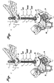
- FIGURE 4 illustrates the essential components of a conventional no-back device 24c designed for applying substantially greater force in the aiding direction than in the opposing direction.
- the lower end portion of the conventional ballscrew 18c has an integral radial ballscrew flange 30 with flat upper and lower surfaces. Flange 30 is sandwiched between upper and lower brake disks 32 and 34.
- An upper ratchet wheel 36 and lower ratchet wheel 38 are mounted for free rotation relative to the conventional ballscrew 18c.
- Upper pawls 40 are mounted in a stationary housing 42, shown diagrammatically in broken lines, and permit free rotation of the upper ratchet wheel 36 in one direction relative to the housing, but are designed to prevent rotation of the upper ratchet wheel in the other direction relative to the housing.
- lower pawls 44 are mounted in the housing and prevent rotation of the lower ratchet wheel 38 in one direction (the direction opposite that which the upper pawls 40 permit the upper ratchet wheel to turn) and prevent rotation of the lower ratchet wheel in the opposite direction.
- the ratchet teeth of the lower ratchet wheel are configured to permit rotation of the ratchet wheel in the "opposing" direction.
- the ballscrew flange cannot turn unless it overcomes the frictional force resulting from the tight engagement of the brake disk 34 between the underside of the ballscrew flange 30 and upper side of the ratchet wheel 38.
- essentially no resistive force is applied in either direction by the upper brake disk 32 and upper ratchet wheel 36 due to the compressive force on the ballscrew which results in a loose fit of these components at the top.
- the applied torque of the no-back device is a function of the tension or compression applied to the ballscrew 18c.
- the bi-directional no-back device 24c applies no or at least very limited resistance to turning of the ballscrew in the opposing direction, but substantial force in the aiding direction, and the brake force and hence torque increases as the applied force T LOAD increases.
- the motor used to trim the horizontal stabilizer meets resistance from substantially only the aerodynamically applied force T LOAD when turning in the opposing direction, but must slip the brake when turning in the aiding direction, regardless of whether the ballscrew 18c is under compression or tension.
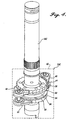
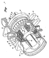
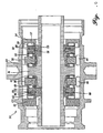
- the improved bi-directional ballscrew no-back device 24 in accordance with the present invention is shown in FIGURES 5 and 6.
- the housing 50 of the no-back device has a top stationary end plate 52 through which the long, hollow, cylindrical ballscrew 18 extends.
- the housing is sealed and filled with lubricant, preferably hydraulic oil because of its consistent viscosity over a wide temperature range.
- the housing also includes a stationary bottom end plate 54.
- the ballscrew has the usual radial ballscrew flange 30.
- An upper brake ring 52 rests on the flat upper side of the ballscrew flange, and a lower brake ring 54 is disposed below the ballscrew flange.
- the brake rings 52 and 54 are sandwiched between the ballscrew flange and upper and lower ratchet wheels 36 and 38 of conventional design except that the ratchet wheels 36 and 38 are mounted for free axial movement along the ballscrew.
- the ratchet wheels cooperate with upper and lower pawl mechanisms 40 and 44 (represented diagrammatically in broken lines in FIGURE 3) which are conventional and are mounted in the housing.
- the underside of the lower ratchet wheel 38 rests against a third brake ring 55 (not visible in FIGURE 3) which, in turn, rests on a two part thrust plate assembly 56, 57 and a thrust bearing 58.
- the upper thrust plate 56 has a flat upper surface, such that the lowermost brake ring 55 is sandwiched between the flat undersurface of the bottom ratchet wheel 38 and the flat upper surface of the thrust plate 56.
- the thrust plate assembly 56, 57 is slidable axially relative to the ballscrew but is connected thereto by a key or spline 59 so that the thrust plates rotate with the ballscrew.
- a fourth brake ring 60 immediately above the upper ratchet wheel 36, and a second two part thrust plate assembly 62, 63 which is slidable axially along the ballscrew 18, but which is connected thereto by a key or spline 64 such that the thrust plates 62, 63 rotate with the ballscrew.
- a top thrust bearing 65 is interposed between the top thrust plate 63 and the underside of the housing upper end plate 52.
- the upper side of the ballscrew flange 30 bears against the brake ring 52 which, in turn, bears against the upper ratchet wheel 36.
- the upper surface of ratchet wheel 36 bears against brake ring 60 which, in turn, bears against the underside of the thrust plate 62.
- the upper pawl mechanism 40 permits freewheeling of the ratchet wheel and, consequently, the ballscrew in the opposing direction, but prevents turning of the ratchet wheel relative to the housing in the aiding direction. In the aiding direction, the ball flange will not be allowed to turn until the braking force is overcome, i.e., by the electric motor.
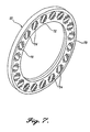
- each of the brake rings is of the design shown in FIGURE 7 and FIGURE 8.
- Brake ring 52 is shown, but rings 54, 55, and 60 are identical.
- the brake ring consists of an annular frame or cage 70 having multiple, circumferentially spaced openings 72 for cylindrical rollers 74.
- the axis of each roller is skewed at an angle a relative to a diameter intersecting the center of the roller.
- the centers of the rollers define a circle having a radius r (referred to as the "brake effective radius"), and each roller is of a length L.
- the skew angle a, radius r, and roller length L all affect the effective coefficient of friction for the composite brake ring.
- each of the outer thrust plates 57, 63 has an inward-directed circumferential rib 80 aligned with the circle of the effective brake radius for centering the load on the rollers.
- the effective coefficient of friction ⁇ eff for each brake ring is affected by the materials used, roller length, brake effective radius r, and skew angle a, but not by the number of rollers.
- the effective coefficient of friction ⁇ eff can be determined experimentally or analytically.
- skew angle a is 36°
- effective brake radius r is 1.42 inches (36.05 millimeters)
- roller diameter is .1969 inch (5 millimeters)
- roller length L is .315 inch (8 millimeters).
- the preferred materials are AISI 52100 steel for the rollers and SAE 9310 carburized steel for the other brake components. This results in ⁇ eff being .0998 when the rollers are new, changing to about .0824 after wear-in. Brake gain when new is approximately 2.85 and after wear-in approximately 2.35.
- the skewed roller brake ring does not have the brake fade nor adverse wear characteristics as described above for the existing bi-directional no-back devices.
- readily available materials may be used for the rollers, roller cage, ballscrew (including the ball flange), and cooperating thrust plates which preferably are the same material as the ballscrew.
Landscapes
- Engineering & Computer Science (AREA)
- General Engineering & Computer Science (AREA)
- Mechanical Engineering (AREA)
- Automation & Control Theory (AREA)
- Aviation & Aerospace Engineering (AREA)
- Braking Arrangements (AREA)
- Transmission Devices (AREA)
Claims (2)
- Dispositif anti-retour (21) pour une vis à billes (18) rotatif dans des directions opposées et présentant une bride de la vis à billes (30) avec des surfaces radiales à ses extrémités opposées et rotatif avec la vis à billes (18), la vis à billes recevant et transférant une charge bidirectionnelle axiale et de couple de torsion provenant d'une source externe, ledit dispositif comprenant :un logement (50) permettant de recevoir une section de la vis à billes (18) comprenant la bride de la vis à billes (30) et permettant un mouvement axial limité de la vis à billes dans le logement ; etun frein à plusieurs étages monté dans le logement (50) et comprenant :des première et seconde roues à rochet (38, 36) rotatives par rapport à la vis à billes (18) et montées à des côtés opposés de la bride de la vis à billes (30), chacune des roues à rochet (38, 36) présentant des surfaces radiales plates à ses extrémités opposées parallèles aux surfaces radiales de la bride de la vis à billes (30) ;un premier cylindre de frein à rouleaux obliques (54) placé en sandwich entre la vis à billes (30) et la première roue à rochet (38) ;un deuxième cylindre de frein à rouleaux obliques (52) placé en sandwich entre la vis à billes (30) et la seconde roue à rochet (36) ;des premier et second ensembles de plaque de poussée (56, 57 ; 62, 63) disposés, respectivement, à des côtés opposés des première et seconde roues à rochet (38, 36) présentant des surfaces radiales plates faisant face à la bride de la vis à billes (30) et parallèles aux surfaces radiales de la bride de la vis à billes ;un troisième cylindre de frein à rouleaux obliques (53) disposé entre la première roue à rochet (38) et le premier ensemble de plaque de poussée (56, 57) ;un quatrième cylindre de frein à rouleaux obliques (60) disposé entre la seconde roue à rochet (36) et le second ensemble de plaque de poussée (62, 63) ;les plaques de poussée (56, 57 ; 62, 68) étant mobiles axialement par rapport à la vis à billes (18) dans le logement (50) pour le transfert des charges compressives exercées sur la vis à billes dans une direction et des efforts de traction exercés sur la vis à billes dans l'autre direction en vue de maintenir les premier et second cylindres de frein à rouleaux obliques (54, 55) en prise étroite par frottement avec la bride de la vis à billes (30), la première roue à rochet (38) et le premier ensemble de plaque de poussée (56, 57) pour les second et quatrième cylindres de frein à rouleaux obliques (52, 60) en prise étroite par frottement avec la bride de la vis à billes (30), la seconde roue à rochet (36) et le second ensemble de plaque de poussée (62, 63) en fonction de la direction de la force externe exercée sur la vis à billes (18) ; etles premier et second ensembles à cliquet (44, 40) montés sur le logement (50) et coopérant avec les première et seconde roues à rochet (38, 36) pour permettre un roulage en roue libre de la première roue à rochet (38) dans une première direction et un roulage en roue libre de la seconde roue à rochet (36) dans la direction opposée, pour le contrôle effectif du couple de freinage appliqué par les freins à plusieurs étages.
- Dispositif anti-retour (24) selon la revendication 1, dans lequel chacun des cylindres de frein à rouleaux obliques (52, 54 ; 55, 60) comprend une cage annulaire (70) avec les rouleaux obliques (74) montés à l'intérieur, les rouleaux obliques présentant des centres définissant un cercle, et les ensembles de plaque de poussée (57, 63) présentant des nervures annulaires faisant face intérieurement (80) alignées sur le cercle défini par les centres des rouleaux.
Applications Claiming Priority (2)
| Application Number | Priority Date | Filing Date | Title |
|---|---|---|---|
| US87394 | 1998-05-29 | ||
| US09/087,394 US6109415A (en) | 1998-05-29 | 1998-05-29 | Bi-directional ballscrew no-back device |
Publications (3)
| Publication Number | Publication Date |
|---|---|
| EP0960811A2 EP0960811A2 (fr) | 1999-12-01 |
| EP0960811A3 EP0960811A3 (fr) | 2000-03-15 |
| EP0960811B1 true EP0960811B1 (fr) | 2004-02-11 |
Family
ID=22204933
Family Applications (1)
| Application Number | Title | Priority Date | Filing Date |
|---|---|---|---|
| EP99201261A Expired - Lifetime EP0960811B1 (fr) | 1998-05-29 | 1999-04-21 | Vis à billes bidirectionelle et autoblocante |
Country Status (4)
| Country | Link |
|---|---|
| US (1) | US6109415A (fr) |
| EP (1) | EP0960811B1 (fr) |
| CA (1) | CA2269022C (fr) |
| DE (1) | DE69914666T2 (fr) |
Families Citing this family (55)
| Publication number | Priority date | Publication date | Assignee | Title |
|---|---|---|---|---|
| GB9911148D0 (en) * | 1999-05-14 | 1999-07-14 | Lucas Ind Plc | Actuator |
| GB0105270D0 (en) * | 2001-03-02 | 2001-04-18 | Lucas Industries Ltd | No-back device |
| GB0107851D0 (en) * | 2001-03-29 | 2001-05-23 | Lucas Industries Ltd | Monitoring apparatus |
| GB0126510D0 (en) * | 2001-11-05 | 2002-01-02 | Lucas Industries Ltd | Screw actuator |
| US6722485B1 (en) * | 2002-10-08 | 2004-04-20 | Moog Inc. | Force-limiting rotary lock |
| US6719106B1 (en) * | 2002-12-17 | 2004-04-13 | The Boeing Company | Duplex skewed-roller brake disc |
| US6827183B1 (en) * | 2003-08-27 | 2004-12-07 | Moog Inc. | Skewed roller brake assembly |
| US20050159992A1 (en) * | 2004-01-16 | 2005-07-21 | Lawrence Richard D. | Process for identifying potential customers for business outsourcing |
| US6997297B2 (en) | 2004-03-09 | 2006-02-14 | Eaton Corporation | Coupling assembly |
| US20050247529A1 (en) * | 2004-05-07 | 2005-11-10 | Gaines Louie T | Aircraft brake acuation system including an internally threaded ballscrew actuator assembly |
| GB0422134D0 (en) * | 2004-10-06 | 2004-11-03 | Goodrich Actuation Systems Ltd | Screw actuator |
| US20080203223A1 (en) * | 2006-06-22 | 2008-08-28 | Cyrot Luc P | Aircraft stabilizer actuator |
| US8393568B2 (en) * | 2006-07-17 | 2013-03-12 | Eaton Corporation | Enhanced lubrication skewed roller clutch assembly and actuator including same |
| US7690597B2 (en) | 2006-07-17 | 2010-04-06 | Eaton Corporation | Flap actuator |
| GB0707122D0 (en) * | 2007-04-13 | 2007-05-23 | Goodrich Actuation Systems Ltd | Actuator arrangement |
| ES2493640T3 (es) | 2008-06-13 | 2014-09-12 | Moog Inc. | Método para determinar la integridad funcional aparente de un dispositivo antirretorno |
| US8109702B2 (en) * | 2008-08-28 | 2012-02-07 | Goodrich Corporation | Attenuated cargo caster |
| US8267601B2 (en) * | 2008-11-04 | 2012-09-18 | James Cameron | Platform for stereoscopy for hand-held film/video camera stabilizers |
| US8281678B2 (en) | 2008-12-30 | 2012-10-09 | Eaton Corporation | Ballscrew assembly with detection feature |
| GB0917059D0 (en) * | 2009-09-29 | 2009-11-11 | Goodrich Actuation Systems Ltd | No-back arrangement |
| FR2953266B1 (fr) | 2009-11-27 | 2011-11-11 | Airbus Operations Sas | Procede de surveillance d'un dispositif d'irreversibilite d'actionneur de plan horizontal reglable, systeme et aeronef correspondants |
| DE102012009149B4 (de) | 2011-05-12 | 2023-03-02 | Liebherr-Aerospace Lindenberg Gmbh | Bidirektional wirkende Rotationssperre bzw. Sperre, ein Bremssystem sowie ein Gewindespindelantrieb |
| FR2988797B1 (fr) * | 2012-04-02 | 2015-04-24 | Sagem Defense Securite | Actionneur electromecanique de surface de vol d'aeronef et aeronef pourvu d'un tel actionneur |
| DE102012000987A1 (de) | 2012-01-21 | 2013-07-25 | Liebherr-Aerospace Lindenberg Gmbh | Rotationssperre |
| FR2989060B1 (fr) * | 2012-04-04 | 2015-01-09 | Ratier Figeac Soc | Systeme anti-retour et actionneur de commande de vol comprenant un tel systeme |
| CN102963521B (zh) * | 2012-11-09 | 2015-04-22 | 北京航空航天大学 | 一种民用飞机水平尾翼中央翼 |
| FR3014842B1 (fr) * | 2013-12-17 | 2017-12-01 | Sagem Defense Securite | Actionneur telescopique et moteur d'aeronef comportant un tel actionneur |
| EP3078589B1 (fr) * | 2015-04-09 | 2018-01-24 | Goodrich Actuation Systems SAS | Dispositif anti-retour pour actionneur de surface de commande de vol |
| US10066715B2 (en) | 2015-04-24 | 2018-09-04 | Moog Inc. | Fail-safe electromechanical actuator |
| US10234012B1 (en) | 2015-06-30 | 2019-03-19 | Rockwell Collins, Inc. | Systems and methods for actively monitoring health of a no back brake device |
| EP3359433B1 (fr) | 2015-10-07 | 2021-08-18 | Meggitt Aircraft Braking Systems Corporation | Diagnostic et pronostic de condition de frein d'aéronef |
| EP3232078B1 (fr) | 2016-04-15 | 2020-06-03 | UTC Aerospace Systems Wroclaw Sp. z o.o. | Dispositif anti-retour avec ressorts à dispersion d'énergie |
| US10822074B2 (en) * | 2016-04-29 | 2020-11-03 | Parker-Hannifin Corporation | Aircraft actuator with no-back, load detent assembly |
| US11046425B2 (en) * | 2016-05-20 | 2021-06-29 | Bombardier Inc. | Apparatus and methods for actuating a double-slotted flap using a slave screw |
| US10443696B1 (en) | 2016-08-03 | 2019-10-15 | Rockwell Collins, Inc. | No-back brake creep inhibitor |
| EP3296586B1 (fr) | 2016-09-20 | 2021-05-05 | Ratier-Figeac SAS | Agencement sans arrière d'actionneur |
| EP3318776B1 (fr) * | 2016-11-07 | 2021-09-22 | Ratier-Figeac SAS | Systeme de frein anti-recul rotatif |
| EP3324065B1 (fr) | 2016-11-21 | 2020-08-12 | Ratier-Figeac SAS | Mécanisme anti-retour |
| FR3063532B1 (fr) * | 2017-03-06 | 2019-04-05 | Safran Electronics & Defense | Actionneur equipe d’un systeme de no back a zone d’inhibition |
| US10975940B2 (en) * | 2017-08-24 | 2021-04-13 | Eaton Intelligent Power Limited | Actuator and method |
| DE102019112005A1 (de) * | 2019-05-08 | 2020-11-12 | Stabilus Gmbh | Bremsvorrichtung, Verfahren zur Steuerung der Bremsvorrichtung |
| DE102019114479A1 (de) * | 2019-05-29 | 2020-12-03 | Liebherr-Aerospace Lindenberg Gmbh | Rücklaufsperre für Flugzeug-Steuersysteme |
| DE102019117178B3 (de) | 2019-06-26 | 2020-09-24 | Liebherr-Werk Ehingen Gmbh | Kran mit verstellbarem Schwebeballast |
| DE102019118649A1 (de) * | 2019-07-10 | 2021-01-14 | Liebherr-Aerospace Lindenberg Gmbh | Rücklaufsperre mit Blockiersicherung |
| US11505313B2 (en) * | 2019-10-29 | 2022-11-22 | Textron Innovations Inc. | Conversion actuation systems and methods for tiltrotor aircraft |
| USD952612S1 (en) * | 2020-03-12 | 2022-05-24 | Sonos, Inc. | Audio device wall mount |
| US11623739B2 (en) | 2020-10-27 | 2023-04-11 | Eaton Intelligent Power Limited | Electromechanical actuator with no-back system |
| US11873092B2 (en) * | 2020-12-16 | 2024-01-16 | The Boeing Company | Trim actuators for horizontal stabilizers and methods of controlling horizontal stabilizers |
| US12078228B2 (en) | 2021-01-20 | 2024-09-03 | Eaton Intelligent Power Limited | Screw drive with self-locking mechanism |
| CA3155438A1 (fr) | 2021-04-15 | 2022-10-15 | Eaton Intelligent Power Limited | Systeme et methode de mise a l'essai d'un systeme d'irreversibilite |
| EP4257484B1 (fr) * | 2022-04-06 | 2025-02-26 | Goodrich Actuation Systems SAS | Frein d'actionneur d'urgence en cas d'emballement |
| EP4269234A1 (fr) * | 2022-04-25 | 2023-11-01 | Eaton Intelligent Power Limited | Cage de roue à rouleaux obliques destinée à être utilisée avec un dispositif rotatif anti-retour |
| US12607223B2 (en) * | 2024-02-09 | 2026-04-21 | Virgin Galactic Holdings, Inc. | Actuator locking system and method |
| US12498026B1 (en) | 2025-01-17 | 2025-12-16 | Hummingbird Aero LLC | Integrity monitors for actuator brakes, and related systems |
| CN120228697B (zh) * | 2025-05-20 | 2025-09-19 | 广东天功自动化科技有限公司 | 一种机械手的丝杆滑台装置 |
Family Cites Families (11)
| Publication number | Priority date | Publication date | Assignee | Title |
|---|---|---|---|---|
| US3583248A (en) * | 1969-04-23 | 1971-06-08 | Abex Ind Canada Ltd | Actuator with no-back mechanism |
| US4030578A (en) * | 1976-05-03 | 1977-06-21 | The Boeing Company | Torque limiter |
| US4459867A (en) * | 1981-12-28 | 1984-07-17 | Sundstrand Corporation | Resettable force limiting device |
| DE3567084D1 (de) * | 1984-03-17 | 1989-02-02 | Lucas Ind Plc | Torque limiter |
| US4697672A (en) * | 1985-03-25 | 1987-10-06 | Sundstrand Corporation | Bi-directional force limiting no-back mechanism |
| US4762205A (en) * | 1987-05-20 | 1988-08-09 | Simmonds Precision | Flight control surface actuator for aircraft including remote braking failure detection |
| US4850458A (en) * | 1988-11-16 | 1989-07-25 | Boeing Company | Bidirectional rotary brake |
| US5299666A (en) * | 1992-09-24 | 1994-04-05 | Sundstrand Corporation | Resettable pilot operated torque limiter |
| US5582390A (en) * | 1994-11-17 | 1996-12-10 | Sundstrand Corporation | Drive apparatus with primary and secondary no-back features |
| US5568704A (en) * | 1995-03-24 | 1996-10-29 | Gmi Holdings, Inc. | Clutchless screw drive door operator |
| US5655636A (en) * | 1995-06-02 | 1997-08-12 | Sundstrand Corporation | Compact actuator including resettable force limiting and anti-backdrive devices |
-
1998
- 1998-05-29 US US09/087,394 patent/US6109415A/en not_active Expired - Lifetime
-
1999
- 1999-04-15 CA CA002269022A patent/CA2269022C/fr not_active Expired - Lifetime
- 1999-04-21 DE DE69914666T patent/DE69914666T2/de not_active Expired - Lifetime
- 1999-04-21 EP EP99201261A patent/EP0960811B1/fr not_active Expired - Lifetime
Also Published As
| Publication number | Publication date |
|---|---|
| DE69914666T2 (de) | 2004-07-29 |
| CA2269022C (fr) | 2006-08-29 |
| US6109415A (en) | 2000-08-29 |
| DE69914666D1 (de) | 2004-03-18 |
| EP0960811A2 (fr) | 1999-12-01 |
| CA2269022A1 (fr) | 1999-11-29 |
| EP0960811A3 (fr) | 2000-03-15 |
Similar Documents
| Publication | Publication Date | Title |
|---|---|---|
| EP0960811B1 (fr) | Vis à billes bidirectionelle et autoblocante | |
| US5944148A (en) | No-back brake | |
| US8291782B1 (en) | Actuator assembly for stabilizers | |
| US8511441B2 (en) | Cone brake no-back | |
| US4909363A (en) | Unidirectional no-back device | |
| EP3078589B1 (fr) | Dispositif anti-retour pour actionneur de surface de commande de vol | |
| US7143888B2 (en) | Combined no-back and torque limiter | |
| US20040040813A1 (en) | No-back device | |
| US3367456A (en) | Torque sensitive brake | |
| US4117912A (en) | Means for reducing the gap between rotor-backing plate interface during brake depressurization | |
| US20110021307A1 (en) | Rotary Actuator | |
| US12559226B2 (en) | Assembly for an aircraft | |
| EP2285673B1 (fr) | Procédé de détermination de l intégrité fonctionnelle apparente d un dispositif anti-retour | |
| US6974015B2 (en) | One-way bidirectional clutch | |
| US6419606B1 (en) | Aircraft control surface drive apparatus | |
| US6692399B2 (en) | Differential torque limiter | |
| JP3504271B2 (ja) | ヘリコプター主回転翼シャフト用スペーサ | |
| CN105905285B (zh) | 用于交通工具的动力驱动单元的减震器组件 | |
| US3630327A (en) | Braking and coupling mechanism | |
| US4275803A (en) | Load brake | |
| US5040643A (en) | Radial torque limiter | |
| WO1992011474A1 (fr) | Section transversale externe non circulaire d'un moyeu de roue associe a un frein a disque | |
| EP3318776B1 (fr) | Systeme de frein anti-recul rotatif | |
| JPS6341800B2 (fr) | ||
| CN108349584A (zh) | 用于飞行器的高升力系统的执行机构 |
Legal Events
| Date | Code | Title | Description |
|---|---|---|---|
| PUAI | Public reference made under article 153(3) epc to a published international application that has entered the european phase |
Free format text: ORIGINAL CODE: 0009012 |
|
| AK | Designated contracting states |
Kind code of ref document: A2 Designated state(s): DE FR IT |
|
| AX | Request for extension of the european patent |
Free format text: AL;LT;LV;MK;RO;SI |
|
| PUAL | Search report despatched |
Free format text: ORIGINAL CODE: 0009013 |
|
| AK | Designated contracting states |
Kind code of ref document: A3 Designated state(s): AT BE CH CY DE DK ES FI FR GB GR IE IT LI LU MC NL PT SE |
|
| AX | Request for extension of the european patent |
Free format text: AL;LT;LV;MK;RO;SI |
|
| RIC1 | Information provided on ipc code assigned before grant |
Free format text: 7B 64C 13/28 A, 7B 64C 5/10 B, 7F 16H 25/20 B, 7F 16D 7/00 B, 7F 16D 59/00 B |
|
| 17P | Request for examination filed |
Effective date: 20000811 |
|
| AKX | Designation fees paid |
Free format text: DE FR IT |
|
| GRAH | Despatch of communication of intention to grant a patent |
Free format text: ORIGINAL CODE: EPIDOS IGRA |
|
| GRAS | Grant fee paid |
Free format text: ORIGINAL CODE: EPIDOSNIGR3 |
|
| GRAA | (expected) grant |
Free format text: ORIGINAL CODE: 0009210 |
|
| AK | Designated contracting states |
Kind code of ref document: B1 Designated state(s): DE FR IT |
|
| REF | Corresponds to: |
Ref document number: 69914666 Country of ref document: DE Date of ref document: 20040318 Kind code of ref document: P |
|
| ET | Fr: translation filed | ||
| PLBQ | Unpublished change to opponent data |
Free format text: ORIGINAL CODE: EPIDOS OPPO |
|
| PLBI | Opposition filed |
Free format text: ORIGINAL CODE: 0009260 |
|
| PLAX | Notice of opposition and request to file observation + time limit sent |
Free format text: ORIGINAL CODE: EPIDOSNOBS2 |
|
| 26 | Opposition filed |
Opponent name: AIRBUS SAS Effective date: 20041110 |
|
| PLAX | Notice of opposition and request to file observation + time limit sent |
Free format text: ORIGINAL CODE: EPIDOSNOBS2 |
|
| PLAS | Information related to reply of patent proprietor to notice(s) of opposition deleted |
Free format text: ORIGINAL CODE: EPIDOSDOBS3 |
|
| PLBB | Reply of patent proprietor to notice(s) of opposition received |
Free format text: ORIGINAL CODE: EPIDOSNOBS3 |
|
| PLBB | Reply of patent proprietor to notice(s) of opposition received |
Free format text: ORIGINAL CODE: EPIDOSNOBS3 |
|
| PLCK | Communication despatched that opposition was rejected |
Free format text: ORIGINAL CODE: EPIDOSNREJ1 |
|
| PLBN | Opposition rejected |
Free format text: ORIGINAL CODE: 0009273 |
|
| STAA | Information on the status of an ep patent application or granted ep patent |
Free format text: STATUS: OPPOSITION REJECTED |
|
| 27O | Opposition rejected |
Effective date: 20060315 |
|
| REG | Reference to a national code |
Ref country code: FR Ref legal event code: PLFP Year of fee payment: 18 |
|
| REG | Reference to a national code |
Ref country code: FR Ref legal event code: PLFP Year of fee payment: 19 |
|
| REG | Reference to a national code |
Ref country code: FR Ref legal event code: PLFP Year of fee payment: 20 |
|
| PGFP | Annual fee paid to national office [announced via postgrant information from national office to epo] |
Ref country code: DE Payment date: 20180427 Year of fee payment: 20 |
|
| PGFP | Annual fee paid to national office [announced via postgrant information from national office to epo] |
Ref country code: FR Payment date: 20180425 Year of fee payment: 20 Ref country code: IT Payment date: 20180423 Year of fee payment: 20 |
|
| REG | Reference to a national code |
Ref country code: DE Ref legal event code: R071 Ref document number: 69914666 Country of ref document: DE |