EP0960813A2 - Treuil de remorquage en particulier pour ailes delta, parapentes et avions ultralégers - Google Patents
Treuil de remorquage en particulier pour ailes delta, parapentes et avions ultralégers Download PDFInfo
- Publication number
- EP0960813A2 EP0960813A2 EP99110103A EP99110103A EP0960813A2 EP 0960813 A2 EP0960813 A2 EP 0960813A2 EP 99110103 A EP99110103 A EP 99110103A EP 99110103 A EP99110103 A EP 99110103A EP 0960813 A2 EP0960813 A2 EP 0960813A2
- Authority
- EP
- European Patent Office
- Prior art keywords
- brake
- drum
- cable
- towing winch
- winch according
- Prior art date
- Legal status (The legal status is an assumption and is not a legal conclusion. Google has not performed a legal analysis and makes no representation as to the accuracy of the status listed.)
- Withdrawn
Links
- XLYOFNOQVPJJNP-UHFFFAOYSA-N water Substances O XLYOFNOQVPJJNP-UHFFFAOYSA-N 0.000 claims abstract description 23
- 230000007246 mechanism Effects 0.000 claims description 10
- 239000002826 coolant Substances 0.000 claims description 6
- 238000002485 combustion reaction Methods 0.000 claims 1
- 239000000110 cooling liquid Substances 0.000 claims 1
- 239000000835 fiber Substances 0.000 claims 1
- 230000037431 insertion Effects 0.000 claims 1
- 238000003780 insertion Methods 0.000 claims 1
- 239000007788 liquid Substances 0.000 claims 1
- 239000012209 synthetic fiber Substances 0.000 claims 1
- 229920002994 synthetic fiber Polymers 0.000 claims 1
- 238000001816 cooling Methods 0.000 abstract description 7
- 238000010276 construction Methods 0.000 abstract description 5
- 239000012530 fluid Substances 0.000 abstract 1
- 239000000725 suspension Substances 0.000 description 5
- 230000005540 biological transmission Effects 0.000 description 4
- 230000006378 damage Effects 0.000 description 4
- 208000027418 Wounds and injury Diseases 0.000 description 3
- 230000035939 shock Effects 0.000 description 2
- 238000004804 winding Methods 0.000 description 2
- 238000010521 absorption reaction Methods 0.000 description 1
- 230000015572 biosynthetic process Effects 0.000 description 1
- 239000000498 cooling water Substances 0.000 description 1
- 238000010438 heat treatment Methods 0.000 description 1
- 208000014674 injury Diseases 0.000 description 1
- 230000001788 irregular Effects 0.000 description 1
- 238000000034 method Methods 0.000 description 1
- 238000013021 overheating Methods 0.000 description 1
- 238000005086 pumping Methods 0.000 description 1
- 238000009966 trimming Methods 0.000 description 1
- 238000009423 ventilation Methods 0.000 description 1
Images


Classifications
-
- B—PERFORMING OPERATIONS; TRANSPORTING
- B64—AIRCRAFT; AVIATION; COSMONAUTICS
- B64F—GROUND OR AIRCRAFT-CARRIER-DECK INSTALLATIONS SPECIALLY ADAPTED FOR USE IN CONNECTION WITH AIRCRAFT; DESIGNING, MANUFACTURING, ASSEMBLING, CLEANING, MAINTAINING OR REPAIRING AIRCRAFT, NOT OTHERWISE PROVIDED FOR; HANDLING, TRANSPORTING, TESTING OR INSPECTING AIRCRAFT COMPONENTS, NOT OTHERWISE PROVIDED FOR
- B64F1/00—Ground or aircraft-carrier-deck installations
- B64F1/04—Ground or aircraft-carrier-deck installations for launching aircraft
- B64F1/08—Ground or aircraft-carrier-deck installations for launching aircraft using winches
Definitions
- the invention relates to a towing winch for in particular Hang gliders, paragliders and light aircraft according to the Preamble of claim 1.
- Towing winches In which the rotation of the rope drum by means of a drum or disc brake can be braked.
- the required and suitable tension is by weight of the aircraft and the pilot.
- the object of the invention is an improved Towing winch especially for aircraft such as hang gliders, To provide paragliders and light aircraft.
- Such a towing winch enables in particular one improved tension presetting, jerky Shocks from the aircraft or the towing vehicle the band brake can be compensated.
- the braking device By building the braking device with a band brake, the one with a braking force via an intermediate Spring element is applied, are suddenly occurring Shocks cushioned by an aircraft or by an aircraft Towing vehicle go out so that the effective traction remains even and there is a risk of damage the equipment or a risk of injury to the pilot be significantly reduced. With changing longer Tension conditions thus remain for the operator Person enough time to readjust the braking force to make.
- Prestressed brake band takes place when the Tow a balance of forces between the coefficient of friction of the Brake band on the brake cylinder and also spring-loaded traction indicator on the other side the brake band is attached.
- the attachment in particular of the control lever, the Display device for the braking force and Rope guide mechanism with the link guide on one single preferably gallows-shaped support frame allows a very compact and simple construction of the towing winch.
- the use of the towing winch is also different, such as possible in water sports.
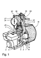
- the towing winch has a base frame 1, from which a substantially gallows-like support frame 2 leads upwards.
- the Directional designations are for illustration purposes only of the individual components in connection with the present Characters.
- the support frame 2 carries in particular one Rope drum 3 on a not described here Bearing and transmission device 4 is mounted, and various operating devices.
- a motor frame 5 is on the side of the base frame 1 a motor 6 releasably attached.
- the attachment of the Motor frame 5 on the base frame 1 takes place, for. B. about a motor frame cross member 8, which on the motor frame 5th is attached and engages over part of the base frame 1.
- Through holes in the engine frame cross member 8 of the motor frame 5 and in the overlapped part of the Guide base frame 1 is a threaded bolt for attachment 9 feasible, which at the same time to define the two Frame sections 1 and 5 can be used on a vehicle.
- the motor 6 is e.g. B. via a slip clutch to the bearing and Gear device 4 and above to the cable drum 3 can be coupled to a rope 7 fastened to the rope drum 3 to be able to wind it up.
- a hand crank or PTO of a towing vehicle to the storage facility 4 be coupled.
- the cable drum 3 consists essentially of a Cable drum cylinder, which is between two drum side walls 10, 10 'sits.
- the cable drum 3 is drivable on one Main shaft 29 mounted, which carries the cable drum cylinder or which is attached to the drum side wall 10 'which the Bearing and gear device 4 is facing.
- the Brake drum instead of on the cable drum 3 on the Main shaft 29 are rotatably attached, on which the Rope drum in turn sits firmly.
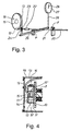
- the brake drum which is also shown in section in Fig. 4 is preferably composed of two circular Brake drum end walls 11, 11 ', between their outer circumference the actual brake cylinder 12 extends around the one Brake band 13 leads.
- the inside brake drum front wall 11 ' is used in the preferred embodiment for direct Attachment to the outer drum side wall 10 of the rope drum 3. This allows one from the brake band 13 to the brake cylinder 12 transmitted braking force on the inside Brake drum front wall 11 'and the drum side wall 10 on the Rope drum 3 are transmitted.
- the other, outside brake drum end wall 11 faces Form a cooling device with independent inventive meaning near its scope a see-through Viewing window 14 and a central opening 15.
- Central opening 15 leads a hose 16 through which from a water tank 17 water 17 'as a coolant in the Brake drum can be filled.
- the water tank 17 is preferably transparent and on the operating side of the Towing winch attached to support frame 2.
- Water pump 18 For pumping Water from the water tank 17 into the brake drum is used Water pump 18, the hand pump in the hose 16th is inserted. The water level in the brake drum is over the viewing window 14 can be checked.
- any other type of Pumps are used.
- the water tank in the upper one Area of the support frame 2 are attached so that water by simply actuating an exhaust valve into the deeper located opening 15 of the brake drum can flow.
- automatic water level meters and Refill devices are installed.
- the hose 16 is largely one Cable drum cover 19 guided concealed, the cable drum to protect the wound rope 7 except for the Encloses the rope execution area.
- a Cable drum cover 19, which is made of a perforated plate on the one hand enables a particularly simple one Attachment of the hose 16 and, on the other hand, a good one Ventilation of the enclosed rope drum 3.
- the piece of wire 23 and the lead attached first end of the brake band 13 vertically to lowest section of the brake cylinder 12 out.
- the brake band 13 leads in a three-quarter circle around the brake cylinder 12 around and then preferably vertically downwards from this way.
- Near the second, downward end of the Brake band 13 has a slot 24 formed therein the piece of wire 23 leading to the first end of the brake band 13 leads, leads freely.
- the second, lower end of the brake band 13 is at one end a balance beam 25 mounted.
- the balance beam 25 is again on a further support element 1 ′′ of the base frame 1 stored, wherein it is pivotable about the bearing point.
- a spring balance train 26 At the the other end of the balance beam 25 is a spring balance train 26 stored, which leads up to a spring balance 27, the is attached to the support frame 2.
- a pointer 28 shows the above the brake bowden cable 20 preset braking force on acts on the brake cylinder 12 or the towed aircraft.
- the second end of the brake band 13 can also be used directly be attached to a pull wire of a spring balance.
- the use of the balance beam 25 and thus the Exploiting leverage and the possibility of one simple force adjustment by moving the Articulation points along the balance beam 25 are omitted.
- Control lever 30 one shown in Fig. 5 Control mechanism with independent inventive Meaning.
- the control lever 30 essentially ends elongated or round bearing element 31, which is close to the Starting point of the control lever 30 mounted on the support frame 2 is.
- the bearing point can z. B. on the side of one first, upstanding support element 32 of the support frame 2 or, as shown, on a second, laterally inclined support element 33 projecting upward.
- the bearing element 31 protrudes laterally Stop pin 35 away. If the control lever 30 in the opposite, second direction via a basic position is pivoted back, the stop pin 35 using leverage against one end of a Bowden cable suspension beam 36.
- the bowden cable suspension beam 36 is pivotable on the support frame 2 stored, preferably on a Bowden cable support element 37, that of the second, diagonally upwards extending support member 33 laterally and obliquely downwards protrudes.
- the second end of the bowden cable suspension beam 36 has a notch 38 in which the End of a Bowden wire 39 is inserted.
- a weird one offers downward Bowden cable support member 37
- the special advantage of this is the end of the To be able to attach motor bowden cable 40.
- the Bowden cable 40 transmits the force acting on it to a clutch, which the motor 6 with the bearing and gear device 4 and the cable drum 3 connects.
- a spring element as one Counter spring 41 attached to the Bowden cable suspension beam 36 compared to the support frame 2 spring loaded.
- the clutch or Bowden cable 40 and the one out of this outstanding Bowden wire 39 are releasably attached to it the motor frame 5 with the motor 6 if necessary from Base frame 1 and the cable drum 3 removed or modular can be distributed.
- control lever 30 can be used for the latter Actuation from an inactive basic position in the first direction, the cable drum 3 braked and at its Actuation from the inactive basic position in the second Direction of the motor 6 are coupled to the cable drum 3, to wind the rope 7 on the rope drum 3.
- the main shaft 29 continues through the transmission and Bearing device 4 through and ends in a rotationally fixed the main shaft 29 connected worm gear 50.
- Das Worm gear 50 is part of the winding device, which is a preferably elliptical backdrop guide or Backdrop roller drives.
- From the worm gear 50 leads a crank rod 51 to the short, angled end of one first, essentially upward thrust and Drawbar 52. Is in its bend or kink area this push and pull rod 52 mounted on the support frame 2, and preferably at the free end of the Bowden cable support element 37, which thus takes on a double function.
- this storage the slightly rotating up and down Movement of the crank rod in a lateral back and forth Movement implemented.
- first push and pull rod 52 At the other end of the first push and pull rod 52 is the first end of a second, substantially horizontal extending push and pull rod 53 stored.
- the second End of the second push and pull rod 53 is on a Kapp- and Rope guide device 54 stored and transmits the The first push and pull rod 52 moves back and forth this.
- the cut and rope guide device 54 is pivotable on a cross member 55 mounted parallel to the Cable drum axis leading laterally from the upper, front end of the obliquely upward-extending support element 33 of the Support frame 2 protrudes. From the bearing point or the bearing axis 56 on the cross member 55 leads from a hollow tube 55, in its lower section, the second push and pull rod 53 is mounted is, essentially downwards.
- the rope 7 is from the Cable drum 3 coming through this hollow tube 57 through and led upwards out of it.
- the rope 7 is at the lower end by two rope guide rollers and at the upper end through two at an angle to the rope 7, in particular about 45 ° extending input guide rollers 58 which the Minimize frictional resistance.
- This arrangement will Rope 7 with rotating rope drum 3 through the trimming and Rope guide device 54 back and forth along the rope drum axis brought about and thereby unwound or wound evenly.
- FIG. 6 Below the cross member 55 leads from the hollow tube Capping mechanism 59 to the operating side of the towing winch.
- the striking plate 60 thereof is shown shown, while in Figs. 1 and 2 also spring-loaded trigger lever 61 is shown.
- a spring balance carrier 62 extends approximately opposite Cross member 55 laterally from the upper, front end of the oblique upwardly extending support member 33 of the support frame 2 for opposite side to the spring scale 27 can be attached to the support frame 2.
Landscapes
- Engineering & Computer Science (AREA)
- Mechanical Engineering (AREA)
- Aviation & Aerospace Engineering (AREA)
- Braking Arrangements (AREA)
- Ropes Or Cables (AREA)
Applications Claiming Priority (2)
| Application Number | Priority Date | Filing Date | Title |
|---|---|---|---|
| DE1998122982 DE19822982A1 (de) | 1998-05-25 | 1998-05-25 | Schleppwinde für insbesondere Hängegleiter, Gleitschirme und Leichtflugzeuge |
| DE19822982 | 1998-05-25 |
Publications (2)
| Publication Number | Publication Date |
|---|---|
| EP0960813A2 true EP0960813A2 (fr) | 1999-12-01 |
| EP0960813A3 EP0960813A3 (fr) | 2001-08-16 |
Family
ID=7868640
Family Applications (1)
| Application Number | Title | Priority Date | Filing Date |
|---|---|---|---|
| EP99110103A Withdrawn EP0960813A3 (fr) | 1998-05-25 | 1999-05-25 | Treuil de remorquage en particulier pour ailes delta, parapentes et avions ultralégers |
Country Status (2)
| Country | Link |
|---|---|
| EP (1) | EP0960813A3 (fr) |
| DE (1) | DE19822982A1 (fr) |
Cited By (1)
| Publication number | Priority date | Publication date | Assignee | Title |
|---|---|---|---|---|
| WO2005058698A1 (fr) * | 2003-12-18 | 2005-06-30 | Paraparts Holding Aps | Appareil de treuil de remorquage destine a des parapentes et des deltaplanes |
Families Citing this family (2)
| Publication number | Priority date | Publication date | Assignee | Title |
|---|---|---|---|---|
| NO2760515T3 (fr) * | 2014-07-03 | 2018-03-24 | ||
| CN108439238B (zh) * | 2018-04-09 | 2023-09-12 | 长沙矿山研究院有限责任公司 | 一种水冷式电液双动力深海装备用绞车 |
Citations (1)
| Publication number | Priority date | Publication date | Assignee | Title |
|---|---|---|---|---|
| DE9401104U1 (de) | 1994-01-24 | 1994-03-10 | Shing, Kao Chen, Taipeh/T'ai-pei | Schlauchwagen |
Family Cites Families (3)
| Publication number | Priority date | Publication date | Assignee | Title |
|---|---|---|---|---|
| US1613680A (en) * | 1925-05-26 | 1927-01-11 | Union Tool Kk | Draw works with cooling apparatus |
| CH603393A5 (en) * | 1975-11-21 | 1978-08-15 | Alfatech Ag | Winch and rope launcher for gliders |
| DE8614242U1 (de) * | 1986-05-26 | 1986-08-21 | Schuhwerk, Christoph, 86476 Neuburg | Abrollwinde |
-
1998
- 1998-05-25 DE DE1998122982 patent/DE19822982A1/de not_active Withdrawn
-
1999
- 1999-05-25 EP EP99110103A patent/EP0960813A3/fr not_active Withdrawn
Patent Citations (1)
| Publication number | Priority date | Publication date | Assignee | Title |
|---|---|---|---|---|
| DE9401104U1 (de) | 1994-01-24 | 1994-03-10 | Shing, Kao Chen, Taipeh/T'ai-pei | Schlauchwagen |
Cited By (1)
| Publication number | Priority date | Publication date | Assignee | Title |
|---|---|---|---|---|
| WO2005058698A1 (fr) * | 2003-12-18 | 2005-06-30 | Paraparts Holding Aps | Appareil de treuil de remorquage destine a des parapentes et des deltaplanes |
Also Published As
| Publication number | Publication date |
|---|---|
| EP0960813A3 (fr) | 2001-08-16 |
| DE19822982A1 (de) | 1999-12-02 |
Similar Documents
| Publication | Publication Date | Title |
|---|---|---|
| DE202014105161U1 (de) | Forstwinde mit verbesserter Führung des Zugseils im Bereich einer oberen Umlenkrolle | |
| DE2307355A1 (de) | Liftvorrichtung fuer den fuehrerstand eines krans in fachwerkausfuehrung | |
| DE19822982A1 (de) | Schleppwinde für insbesondere Hängegleiter, Gleitschirme und Leichtflugzeuge | |
| EP1006693A2 (fr) | Carte insérable pour une station de réseau avec fonction de routage intégrée | |
| DE2529620C3 (de) | Vorrichtung zum Antrieb eines Transportseiles, insbesondere für die Holzbringung | |
| DE1756079A1 (de) | Vorrichtung zum Abheben und Absenken von Kraftfahrzeugen | |
| DE3905476C2 (fr) | ||
| EP1157606A2 (fr) | Méthode et dispositif pour actionner un appareil d'irrigation automoteur | |
| DE3605508A1 (de) | Bremse fuer einen transportwagen | |
| DE3938942C2 (fr) | ||
| DE2202992C3 (de) | Schlag- oder Schlagbohrgerät | |
| DE2115403B2 (de) | Seilspannungsregler fuer steuerseile | |
| DE942048C (de) | Haspel, vorzugsweise Schlepperhaspel mit Druckluftantrieb | |
| DE504051C (de) | Vorrichtung fuer Flugzeugraeder mit einer durch den Flugzeugfuehrer direkt gesteuerten Bremsung und einer selbsttaetigen Bremsloesungsvorrichtung | |
| AT144077B (de) | Kraftgetriebener Wagenschieber. | |
| DE949123C (de) | Vorrichtung zum Beladen von Transportfahrzeugen, insbesondere mit Blochholz | |
| DE805843C (de) | Anordnung zum Schalten von Fahrzeuggetrieben | |
| CH413892A (de) | Antriebsanordnung eines Schienentriebfahrzeuges für wahlweisen Zahnrad- oder Adhäsionsbetrieb | |
| AT237030B (de) | Schilift | |
| DE8233987U1 (de) | Startwinde fuer haengegleiter | |
| DE2835175A1 (de) | Abseil-rettungsgeraet | |
| DE921249C (de) | Winde, insbesondere Seilwinde fuer Kraftfahrzeuge | |
| DE7103612U (de) | Hoehensicherungsgeraet | |
| DE574122C (de) | Verfahren zur Abkuerzung der Steigzeit von Luftschiffen beim Abfahren | |
| AT153848B (de) | Selbsttätige Einholvorrichtung für die einzelnen Schleppseile einer Schleppseilbahn für Skiläufer. |
Legal Events
| Date | Code | Title | Description |
|---|---|---|---|
| PUAI | Public reference made under article 153(3) epc to a published international application that has entered the european phase |
Free format text: ORIGINAL CODE: 0009012 |
|
| AK | Designated contracting states |
Kind code of ref document: A2 Designated state(s): AT BE CH CY DE DK ES FI FR GB GR IE IT LI LU MC NL PT SE |
|
| AX | Request for extension of the european patent |
Free format text: AL;LT;LV;MK;RO;SI |
|
| PUAL | Search report despatched |
Free format text: ORIGINAL CODE: 0009013 |
|
| AK | Designated contracting states |
Kind code of ref document: A3 Designated state(s): AT BE CH CY DE DK ES FI FR GB GR IE IT LI LU MC NL PT SE |
|
| AX | Request for extension of the european patent |
Free format text: AL;LT;LV;MK;RO;SI |
|
| AKX | Designation fees paid | ||
| REG | Reference to a national code |
Ref country code: DE Ref legal event code: 8566 |
|
| STAA | Information on the status of an ep patent application or granted ep patent |
Free format text: STATUS: THE APPLICATION IS DEEMED TO BE WITHDRAWN |
|
| 18D | Application deemed to be withdrawn |
Effective date: 20020219 |