EP0960963A2 - Palier à disques d'appui de rotor de filage avec extremité ouverte - Google Patents
Palier à disques d'appui de rotor de filage avec extremité ouverte Download PDFInfo
- Publication number
- EP0960963A2 EP0960963A2 EP99107857A EP99107857A EP0960963A2 EP 0960963 A2 EP0960963 A2 EP 0960963A2 EP 99107857 A EP99107857 A EP 99107857A EP 99107857 A EP99107857 A EP 99107857A EP 0960963 A2 EP0960963 A2 EP 0960963A2
- Authority
- EP
- European Patent Office
- Prior art keywords
- bearing according
- groove
- cleaning groove
- cleaning
- covering
- Prior art date
- Legal status (The legal status is an assumption and is not a legal conclusion. Google has not performed a legal analysis and makes no representation as to the accuracy of the status listed.)
- Withdrawn
Links
Images



Classifications
-
- F—MECHANICAL ENGINEERING; LIGHTING; HEATING; WEAPONS; BLASTING
- F16—ENGINEERING ELEMENTS AND UNITS; GENERAL MEASURES FOR PRODUCING AND MAINTAINING EFFECTIVE FUNCTIONING OF MACHINES OR INSTALLATIONS; THERMAL INSULATION IN GENERAL
- F16C—SHAFTS; FLEXIBLE SHAFTS; ELEMENTS OR CRANKSHAFT MECHANISMS; ROTARY BODIES OTHER THAN GEARING ELEMENTS; BEARINGS
- F16C37/00—Cooling of bearings
- F16C37/007—Cooling of bearings of rolling bearings
-
- D—TEXTILES; PAPER
- D01—NATURAL OR MAN-MADE THREADS OR FIBRES; SPINNING
- D01H—SPINNING OR TWISTING
- D01H4/00—Open-end spinning machines or arrangements for imparting twist to independently moving fibres separated from slivers; Piecing arrangements therefor; Covering endless core threads with fibres by open-end spinning techniques
- D01H4/04—Open-end spinning machines or arrangements for imparting twist to independently moving fibres separated from slivers; Piecing arrangements therefor; Covering endless core threads with fibres by open-end spinning techniques imparting twist by contact of fibres with a running surface
- D01H4/08—Rotor spinning, i.e. the running surface being provided by a rotor
- D01H4/12—Rotor bearings; Arrangements for driving or stopping
-
- D—TEXTILES; PAPER
- D01—NATURAL OR MAN-MADE THREADS OR FIBRES; SPINNING
- D01H—SPINNING OR TWISTING
- D01H4/00—Open-end spinning machines or arrangements for imparting twist to independently moving fibres separated from slivers; Piecing arrangements therefor; Covering endless core threads with fibres by open-end spinning techniques
- D01H4/04—Open-end spinning machines or arrangements for imparting twist to independently moving fibres separated from slivers; Piecing arrangements therefor; Covering endless core threads with fibres by open-end spinning techniques imparting twist by contact of fibres with a running surface
- D01H4/22—Cleaning of running surfaces
-
- F—MECHANICAL ENGINEERING; LIGHTING; HEATING; WEAPONS; BLASTING
- F16—ENGINEERING ELEMENTS AND UNITS; GENERAL MEASURES FOR PRODUCING AND MAINTAINING EFFECTIVE FUNCTIONING OF MACHINES OR INSTALLATIONS; THERMAL INSULATION IN GENERAL
- F16C—SHAFTS; FLEXIBLE SHAFTS; ELEMENTS OR CRANKSHAFT MECHANISMS; ROTARY BODIES OTHER THAN GEARING ELEMENTS; BEARINGS
- F16C19/00—Bearings with rolling contact, for exclusively rotary movement
- F16C19/50—Other types of ball or roller bearings
- F16C19/507—Other types of ball or roller bearings with rolling elements journaled in one of the moving parts, e.g. stationary rollers to support a rotating part
-
- F—MECHANICAL ENGINEERING; LIGHTING; HEATING; WEAPONS; BLASTING
- F16—ENGINEERING ELEMENTS AND UNITS; GENERAL MEASURES FOR PRODUCING AND MAINTAINING EFFECTIVE FUNCTIONING OF MACHINES OR INSTALLATIONS; THERMAL INSULATION IN GENERAL
- F16C—SHAFTS; FLEXIBLE SHAFTS; ELEMENTS OR CRANKSHAFT MECHANISMS; ROTARY BODIES OTHER THAN GEARING ELEMENTS; BEARINGS
- F16C2340/00—Apparatus for treating textiles
- F16C2340/18—Apparatus for spinning or twisting
Definitions
- the cleaning groove has a depth between 0.2 mm and 2.0 mm.
- the width is Cleaning groove formed smaller than the width of the cooling groove, so that a Sufficient cooling is achieved without the tread being too large Suffers weakening.
- the cleaning groove already achieves cleaning of the rotor shaft with a smaller width than this for the function of the Cooling groove is required.
- the cooling groove advantageously has a width between 0.6 mm and 1.6 mm, particularly cheap between 0.8 and 1.4 mm.
- the depth the cooling groove is conveniently between 0.8 mm and 2.0 mm.
- the covering of the support disk is made of Polyurethane because its electrical conductivity is reduced can without the material properties deteriorating too much become.
- Is particularly favorable for reducing the electrical Resistance of the covering of a material with a Additive is provided, which in turn is electrically conductive, especially is an additive that consists of a metal powder.
- carbon e.g. cast iron
- the cleaning groove has a depth of at least 5 ⁇ m and at most 0.4 mm. This will ensures that safe cleaning takes place.
- the cleaning groove has a depth between 10 ⁇ m and 0.2 mm. This depth ensures that the dirt when touching the shaft and Support disc covering has enough space available and not again is rolled on. The rotor shaft is significantly weakened not doing that.
- the cleaning groove has a width of at least 0.1 mm and at most 1.0 mm, with a range of the width of the cleaning groove being particularly favorable between 0.2 mm and 0.6 mm.
- the storage 1 of Figure 1 has a cleaning groove 3 on all of its four support disks 14, but it is also conceivable that only one supporting disk 14 with a cleaning groove per wedge gap 141 3 is equipped. It is then advantageous in each case that support disk which experiences the lower load due to the running conditions. As a result, the weakening of the covering 143, which is caused by the introduction the cleaning groove 3 experiences, somewhat compensated.
- the cleaning grooves 3 of all support disks 14 with respect to plane E, which are parallel to edge 142 runs, partially inclined (see Figure 2, angle ⁇ ).
- the inclination of the Cleaning groove 3 can provide an axial thrust on the rotating spinning rotor generate that is sometimes not desired.
- the cleaning grooves 3 of a pair of support disks which have a wedge gap 141 forms, arranged so that their thrust is canceled.
- one wedge groove per wedge gap 141 3 owns.
- the Shafts 13 are not parallel to each other, but skewed, see above that an axial stroke is exerted on the rotor shaft by the support disks becomes.
- This is supported in a known manner on an axial bearing 101.
- This can, for example, be designed as a thrust bearing or, as in the exemplary embodiment indicated by Figure 1, in the form of an aerostatic thrust bearing.
- the cleaning groove has a width of 1.0 mm and a groove depth of also 1.0 mm. This ensures not only good cleaning in the embodiment of Figure 2 of the rotor shaft of dirt but also a recording the dirt particles removed from the rotor shaft. These dirt particles can then operate the support disc by centrifugal force again leave and are eliminated from the area of the rotor bearing.
- the depth of 1.0 mm to 2.0 mm also ensures one Cooling of the support disc covering.
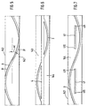
- the cleaning grooves 3 of Figure 3 are less wide than the cleaning groove 3 in Figure 2.
- the width here is only 0.4 mm, so that the interruption of the tread 144, viewed across the edge 142, is even less than is the case with FIG. 2.
- the groove edges 31, the Pass area of an edge 142 of the support disc, run likewise as in Figure 2 such that a covering 143 between the groove edge 31 and the edge 142 of the support disc remains. As in FIG. 1, this ensures a smooth running of the spinning rotor on the support disc.
- the depth of the cleaning grooves 3 is only 0.3 mm in this embodiment.
- FIG. 4 shows another embodiment of a covering 143 of a support disk, in which the tread 144, as in FIG. 3, of two Cleaning grooves is interrupted, however, differently than in Figure 3 each are designed so that both cleaning grooves each from edge 142nd run to edge 142. So each of the two cleaning grooves has the same geometric relationships such as the cleaning groove 3 of Figure 2. Die two cleaning grooves 3 of Figure 4 are only 180 °, based on the circumference of the support disc, offset from one another. This has the consequence that the two cleaning grooves 3 of Figure 4 on the tread 144 twice cross. One of the crossing points can be seen in the middle of FIG. 4, the other crossing is partly on the left edge of Figure 4 and Part seen on the right edge of Figure 4. To at the crossroads the two are not to weaken the tread too much Cleaning grooves 3 of Figure 4 each only 0.2 mm wide. The clarity half of the grooves are made wider in all drawings.
- a small depth and width of the cleaning groove 3 causes also a safe function because the crossing of the crossing point both grooves through the rotor shaft due to a slight depth of the cleaning groove 3 is facilitated.
- the tread experiences 144 the largest interruption of the covering 143 by the grooves. In the embodiment of Figure 6, the interruption is favorable anyway still far below 40%.
- Figure 8 shows a section through a support disc with a cleaning groove 3 in the pad 143, which forms the tread 144 on its outer circumference.
- the Support disc consists of a base body 5, for example as Aluminum injection molded part is formed.
- the support disc 14 has in her Center a bore 51 through which it on the shaft 13 of a support disc bearing 12 is attached by means of an interference fit (see Figure 1).
- the cleaning groove 3 migrates from Area of the left edge 142 to the right edge 142 of the support disc.
- the area of the transition between base body 5 and covering 143 is the outer circumference of the base body 5 designed in a special way, so that better adhesion between base body 5 and pad 143 can be guaranteed can.
- FIG. 10 shows an open-end spinning rotor 2 for an inventive one Storage.
- Figure 10 shows the resting of the rotor shaft 21 two support disks 14. These are equipped with a central cooling groove 4. To prevent dust or dirt particles from sticking to the rotor shaft 21, this has in the area with which it has the support washers 14 comes into contact, a cleaning groove 6, the thread groove-like winds around the shaft.
- the cleaning grooves 6 are with a Inclination to the axis 22 of the shaft 21 and have such Pitch, similar to a thread pitch, that it has at least one turn in the area that is touched by the support disc. Outside of the contact area through the support disc, the cleaning grooves run out. Outside they are for cleaning or keeping the Rotor shaft is not required.
Landscapes
- Engineering & Computer Science (AREA)
- General Engineering & Computer Science (AREA)
- Mechanical Engineering (AREA)
- Textile Engineering (AREA)
- Spinning Or Twisting Of Yarns (AREA)
Applications Claiming Priority (2)
| Application Number | Priority Date | Filing Date | Title |
|---|---|---|---|
| DE19824286 | 1998-05-29 | ||
| DE19824286A DE19824286A1 (de) | 1998-05-29 | 1998-05-29 | Lagerung für einen Offenend-Spinnrotor mittels Stützscheiben |
Publications (2)
| Publication Number | Publication Date |
|---|---|
| EP0960963A2 true EP0960963A2 (fr) | 1999-12-01 |
| EP0960963A3 EP0960963A3 (fr) | 2001-04-04 |
Family
ID=7869443
Family Applications (1)
| Application Number | Title | Priority Date | Filing Date |
|---|---|---|---|
| EP99107857A Withdrawn EP0960963A3 (fr) | 1998-05-29 | 1999-04-21 | Palier à disques d'appui de rotor de filage avec extremité ouverte |
Country Status (3)
| Country | Link |
|---|---|
| US (1) | US6220761B1 (fr) |
| EP (1) | EP0960963A3 (fr) |
| DE (1) | DE19824286A1 (fr) |
Cited By (1)
| Publication number | Priority date | Publication date | Assignee | Title |
|---|---|---|---|---|
| EP1316629A1 (fr) * | 2001-11-29 | 2003-06-04 | Rieter Ingolstadt Spinnereimaschinenbau AG | Disque de support et roulement pour un rotor de filature |
Families Citing this family (12)
| Publication number | Priority date | Publication date | Assignee | Title |
|---|---|---|---|---|
| DE10018440A1 (de) * | 2000-04-13 | 2001-10-18 | Rieter Ingolstadt Spinnerei | Stützscheibe für eine Stützscheibenlagerung für Spinnrotoren |
| DE10039121B4 (de) * | 2000-08-07 | 2007-04-12 | Carl Freudenberg Kg | Stützscheibe für die Lagerung eines Rotors |
| DE10237007A1 (de) * | 2001-11-29 | 2003-06-12 | Rieter Ingolstadt Spinnerei | Stützscheibe und Lagerung für einen Spinnrotor |
| DE10200743A1 (de) * | 2002-01-10 | 2003-07-24 | Rieter Ingolstadt Spinnerei | Grundkörper für die Stützscheibe einer OE-Rotorlagerung |
| DE10209007A1 (de) * | 2002-02-26 | 2003-09-04 | Stahlecker Gmbh Wilhelm | Stützscheibe für eine Stützscheibenlagerung von Offenend-Spinnrotoren |
| DE10228208A1 (de) * | 2002-06-24 | 2004-01-22 | Rieter Ingolstadt Spinnereimaschinenbau Ag | Austauschbares Bauteil einer Textilmaschine mit einer Oberflächenbeschichtung oder -vergütung und Erfassungseinrichtung hierfür |
| DE102005048041A1 (de) * | 2005-10-07 | 2007-04-12 | Saurer Gmbh & Co. Kg | Fadenabzugseinrichtung für eine Kreuzspulen herstellende Textilmaschine |
| DE102006053734A1 (de) * | 2006-11-15 | 2008-05-21 | Oerlikon Textile Gmbh & Co. Kg | Rotorantrieb einer Offenend-Spinnvorrichtung |
| US8296951B2 (en) * | 2009-06-25 | 2012-10-30 | Young Keun Hyun | Method of manufacturing a fixture of a dental implant |
| DE102012014660A1 (de) * | 2012-07-24 | 2014-01-30 | Saurer Germany Gmbh & Co. Kg | Stützscheibenlagerung für eine Offenend-Spinneinrichtung |
| DE102015104491A1 (de) * | 2015-03-25 | 2016-09-29 | Rieter Ingolstadt Gmbh | Spinnrotor mit einem Laufbelag, Stützscheibe zur Lagerung eines Spinnrotors sowie Offenendspinnvorrichtung mit einem Spinnrotor und einer Lagervorrichtung mit Stützscheiben |
| CN107699998A (zh) * | 2017-10-18 | 2018-02-16 | 苏州多道自动化科技有限公司 | 一种用于转杯纺纱机的带散热的一体式轴承座 |
Family Cites Families (19)
| Publication number | Priority date | Publication date | Assignee | Title |
|---|---|---|---|---|
| DE2112913B2 (de) | 1971-03-17 | 1975-02-27 | Wilhelm Stahlecker Gmbh, 7341 Reichenbach | Lagerung der Spinnturbine eines Offen-End-Spinnaggregates |
| JPS5551819Y2 (fr) * | 1972-11-24 | 1980-12-02 | ||
| DE2428514B1 (de) * | 1974-06-12 | 1975-09-18 | Kugelfischer G Schaefer & Co | Reibscheibe fuer den Reibantrieb von hochtourig umlaufenden Falschdrall-Drehroehrchen |
| US4149365A (en) * | 1976-05-01 | 1979-04-17 | Kabushiki Kaisha Toyoda Jidoshokki Seisakusho | Arrangement for preventing axial displacement of spinning rotor spindle |
| DE3342768A1 (de) * | 1983-11-25 | 1985-06-05 | Schubert & Salzer Maschinenfabrik Ag, 8070 Ingolstadt | Stuetzscheibenlager |
| US5178473A (en) | 1983-11-25 | 1993-01-12 | Schubert & Salzer Maschinenfabrik Aktiengesellschaft | Supporting-disk bearing |
| DE3630256A1 (de) * | 1986-09-05 | 1988-03-17 | Schlafhorst & Co W | Stuetzscheibenlagerung an einem oe-spinnaggregat |
| DE3709576A1 (de) * | 1987-03-24 | 1988-10-06 | Stahlecker Fritz | Lagerung und antrieb fuer einen spinnrotor |
| DE3719445A1 (de) * | 1987-06-11 | 1988-12-22 | Fritz Stahlecker | Stuetzscheibe fuer eine stuetzscheibenlagerung |
| DE3730705A1 (de) * | 1987-09-12 | 1989-03-23 | Fritz Stahlecker | Vorrichtung zum oe-rotorspinnen mit einem spinnrotor |
| DE3734545A1 (de) * | 1987-10-13 | 1989-05-03 | Schubert & Salzer Maschinen | Offenend-rotorspinnmaschine |
| DE4024268A1 (de) * | 1990-07-31 | 1992-02-06 | Lehmann & Voss & Co | Elektrisch leitfaehiges kunststoffelement und seine verwendung |
| DE4218173A1 (de) * | 1991-06-04 | 1992-12-10 | Nissei Plastics Ind Co | Leitende harzzusammensetzung und herstellungsverfahren dafuer |
| DE4429028A1 (de) | 1994-08-16 | 1996-02-22 | Hoechst Ag | Elektrisch leitfähige thermoplastische Verbundwerkstoffe und Verfahren zu ihrer Herstellung |
| DE19549466C2 (de) | 1995-03-25 | 1999-10-14 | Rieter Ingolstadt Spinnerei | Stützscheibe |
| US5551226A (en) * | 1995-09-01 | 1996-09-03 | Richard M. Keir | Disk for open end spinning |
| DE19712916A1 (de) * | 1997-03-27 | 1998-10-01 | Novibra Gmbh | Stützscheibe für eine Stützscheibenlagerung von OE-Spinnrotoren |
| DE19719791A1 (de) * | 1997-05-10 | 1998-11-12 | Novibra Gmbh | Stützscheibe für eine Stützscheibenlagerung von OE-Spinnrotoren |
| DE19818125B4 (de) * | 1998-04-23 | 2006-07-27 | Spindelfabrik Süssen Schurr Stahlecker & Grill GmbH | Stützscheibe für eine Stützscheibenlagerung von Offenend-Spinnrotoren |
-
1998
- 1998-05-29 DE DE19824286A patent/DE19824286A1/de not_active Withdrawn
-
1999
- 1999-04-21 EP EP99107857A patent/EP0960963A3/fr not_active Withdrawn
- 1999-05-27 US US09/323,187 patent/US6220761B1/en not_active Expired - Fee Related
Cited By (1)
| Publication number | Priority date | Publication date | Assignee | Title |
|---|---|---|---|---|
| EP1316629A1 (fr) * | 2001-11-29 | 2003-06-04 | Rieter Ingolstadt Spinnereimaschinenbau AG | Disque de support et roulement pour un rotor de filature |
Also Published As
| Publication number | Publication date |
|---|---|
| EP0960963A3 (fr) | 2001-04-04 |
| US6220761B1 (en) | 2001-04-24 |
| DE19824286A1 (de) | 1999-12-02 |
Similar Documents
| Publication | Publication Date | Title |
|---|---|---|
| EP0158242B1 (fr) | Palier radial à contact lisse | |
| DE69618508T2 (de) | Dichtungsvorrichtung für Wälzlager | |
| EP0960963A2 (fr) | Palier à disques d'appui de rotor de filage avec extremité ouverte | |
| DE4034826A1 (de) | Dynamisches drucklager | |
| DE10145610A1 (de) | Schneidgarnitur einer Kettensäge | |
| DE2933505C2 (de) | Kreuzgelenk | |
| DE10158768B4 (de) | Radialkolbenpumpe | |
| DE2838768B2 (de) | Mehrflächengleitlager | |
| DE19781289B4 (de) | Getriebe mit Lageranordnung | |
| DE2123981A1 (de) | Rollenlager | |
| EP0246424A2 (fr) | Palier lisse axial pour épaulement de butée d'arbre de boîte de vitesses | |
| EP0806579A2 (fr) | Palier axial à auto-alignement | |
| EP0885829B1 (fr) | Distributeur de fil et dispositif d'accouplement | |
| DE2152125A1 (de) | Rolle fuer ein Waelzlager | |
| DE1286344B (de) | Radialwaelzlager | |
| DE3246863A1 (de) | Waelzlager mit geteilter lagerhuelse | |
| EP1146152B1 (fr) | Disque de support comportant une couche en caoutchouc pour un palier à disques supportant un rotor à filature | |
| DE3041003C1 (de) | Maschine zur Herstellung von Brucheis | |
| DE19750113A1 (de) | Wälzlager/Wälzführung | |
| DE10110668B4 (de) | Kurvennuttrieb | |
| DE102006014108B4 (de) | Wälzlager | |
| DE10130898C2 (de) | Handstück für ein medizinisches oder kosmetisches Bearbeitungsgerät | |
| DE3447600A1 (de) | Stuetzscheibenlagerung fuer oe-spinnrotoren | |
| CH654879A5 (de) | Zahnradmaschine, insbesondere zahnradpumpe fuer loesungen oder schmelzen von polymeren. | |
| DE3611907C2 (fr) |
Legal Events
| Date | Code | Title | Description |
|---|---|---|---|
| PUAI | Public reference made under article 153(3) epc to a published international application that has entered the european phase |
Free format text: ORIGINAL CODE: 0009012 |
|
| AK | Designated contracting states |
Kind code of ref document: A2 Designated state(s): CH DE ES FR IT LI |
|
| AX | Request for extension of the european patent |
Free format text: AL;LT;LV;MK;RO;SI |
|
| PUAL | Search report despatched |
Free format text: ORIGINAL CODE: 0009013 |
|
| AK | Designated contracting states |
Kind code of ref document: A3 Designated state(s): AT BE CH CY DE DK ES FI FR GB GR IE IT LI LU MC NL PT SE |
|
| AX | Request for extension of the european patent |
Free format text: AL;LT;LV;MK;RO;SI |
|
| 17P | Request for examination filed |
Effective date: 20010509 |
|
| AKX | Designation fees paid |
Free format text: CH DE ES FR IT LI |
|
| 17Q | First examination report despatched |
Effective date: 20021105 |
|
| STAA | Information on the status of an ep patent application or granted ep patent |
Free format text: STATUS: THE APPLICATION IS DEEMED TO BE WITHDRAWN |
|
| 18D | Application deemed to be withdrawn |
Effective date: 20040608 |