EP0960970B1 - Table de repassage avec dispositif pour accessoire sur la face inférieure de la planche de repassage - Google Patents
Table de repassage avec dispositif pour accessoire sur la face inférieure de la planche de repassage Download PDFInfo
- Publication number
- EP0960970B1 EP0960970B1 EP98124387A EP98124387A EP0960970B1 EP 0960970 B1 EP0960970 B1 EP 0960970B1 EP 98124387 A EP98124387 A EP 98124387A EP 98124387 A EP98124387 A EP 98124387A EP 0960970 B1 EP0960970 B1 EP 0960970B1
- Authority
- EP
- European Patent Office
- Prior art keywords
- ironing
- ironing board
- board according
- base plate
- iron
- Prior art date
- Legal status (The legal status is an assumption and is not a legal conclusion. Google has not performed a legal analysis and makes no representation as to the accuracy of the status listed.)
- Expired - Lifetime
Links
- 238000010409 ironing Methods 0.000 title claims description 47
- XEEYBQQBJWHFJM-UHFFFAOYSA-N Iron Chemical compound [Fe] XEEYBQQBJWHFJM-UHFFFAOYSA-N 0.000 claims description 54
- 229910052742 iron Inorganic materials 0.000 claims description 27
- 229920001296 polysiloxane Polymers 0.000 claims description 2
- 238000003780 insertion Methods 0.000 description 1
- 230000037431 insertion Effects 0.000 description 1
- 235000000396 iron Nutrition 0.000 description 1
- 238000000034 method Methods 0.000 description 1
Images
Classifications
-
- D—TEXTILES; PAPER
- D06—TREATMENT OF TEXTILES OR THE LIKE; LAUNDERING; FLEXIBLE MATERIALS NOT OTHERWISE PROVIDED FOR
- D06F—LAUNDERING, DRYING, IRONING, PRESSING OR FOLDING TEXTILE ARTICLES
- D06F81/00—Ironing boards
- D06F81/003—Ironing boards with flat iron support
Definitions
- the invention relates to an ironing board according to the preamble of claim 1.
- the carrier is for the iron attached to one end of the ironing board and he protrudes from this end. This increases the length of the ironing board, what u.U. stowing the ironing board when not in use makes it difficult for serious people is, however, that when ironing larger ironing items in particular, some of them comes to lie on the carrier and can get caught on it. It can also happen that the iron is accidentally thrown down.
- a previously described ironing board is known from US 3,268,192 A.
- An ironing board with discloses an iron shelf protruding laterally, US Pat. No. 2,723,097 from DE 89 05 609 U an ironing table with a swiveling, side iron shelf, laundry shelf, Sleeve board, clothes rack and cable routing known. Additional side iron shelves result from US 3 603 543 A and US 2 438 054 A.
- GB 2 072 711 A discloses a longitudinally arranged behind an ironing board Shelf.
- the object of the invention is to provide an ironing board of the generic type, in which a hindrance to the ironing process by the wearer for the Iron and an increase in the space required by the carrier is avoided.
- first and second spaced holders each with at least one Opening provided, and the carrier is provided with side projections, the can be inserted into the openings in the holders.
- the holder can from in the longitudinal direction of the ironing board, mutually parallel first and second rails are formed, each having several in series, which face the openings in the other rail. This can the carrier can be placed in different positions so that it is iron of different widths can take up without the iron off the ironing board protrudes.
- the rails on the one hand from a section of the Frame and on the other hand from the opposite of this frame section Section of the guide rail can be formed.
- the carrier preferably consists of a base plate with flat projections on one side and with angled protrusions on the other side.
- the first holder is then with narrower slots for insertion of the flat protrusions and the second holder is with wider slots for inserting the Provide ends of the angled projections.
- the straight protrusions are inserted into the narrower slots and the Base plate moved so far towards the first holder that the ends the angled projections through the wider slots in the second holder can be passed through.
- the base plate is then moved so that the ends of the angled projections are clamped to the second holder become.
- the clamping element can be rotatably mounted in the base plate and have a clamping plate which at the end which in the clamping position Opposed ends of the angled projections is rounded.
- the Clamping plate can have a handle on its lower side when inserted to turn the clamping plate and on its top one by one Pin connected bolt.
- the base plate is then with one Provide an elongated hole through which the bolt can be passed and that has a hole-like extension in which the pin acting as a pivot comes to rest. After passing the bolt through the longitudinal slot and slight rotation of the clamping plate is secured against falling out.
- the base plate can be used to lock the clamping plate in the clamping position be provided with knobs on the top on both sides of the elongated hole, between which the bolt comes to rest in the clamped position.
- the carrier elements of the carrier depend on the type and shape of the to be picked up Iron.
- the carrier preferably has two spaced, U-shaped brackets who put the iron on or with the Handle can be hung. To prevent the iron from slipping off the temples the lower legs can run diagonally upwards. It can too Conditions are provided, which are placed on the lower legs of the bracket and are provided with locking elements for releasably holding the iron.
- the terms are preferably clipped onto the bracket and can, depending on the type of iron be replaced.
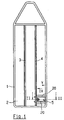
- an ironing board which has a frame 1 on which an ironing board 2 is attached to the underside of the ironing board 2 are guide rails 3 and 4 attached for a foot frame, not shown.
- a support for an iron generally designated 5 releasably attached.
- the carrier 5 has a base plate which has flat projections on one side and the opposite side has angled projections.
- To attach the Base plate on the ironing board 2 are in the embodiment in the opposite Walls of the guide rail 4 and the frame 1 slots are provided, the width of which is such that, on the one hand, the angled ends of the extensions and on the other hand the flat extensions can be passed through.
- the one So slots are wider than the other slots.
- To hold the base plate the flat extensions pushed through the slots in frame 1 until the angled Extensions are guided through the wider slots in the guide rail 4 then the base plate is pressed down so that the ends place the extensions behind the wall of the guide rail 4. Now the base plate clamped by a clamping element which is rotatably mounted in the base plate.
- the clamping element has a clamping plate with angled ends, which at its a handgrip when installed and a handle on top has bolt connected by a pin.
- an elongated hole is provided in the base plate through which the bolt from below is performed and which has a hole-like extension in which the pin comes to rest.
- Support elements for an iron are attached to the base plate.
- two U-shaped brackets 20 are welded onto the underside of the base plate, an iron is hung on its lower leg with its handle can. In order to avoid slipping off the legs, they run obliquely up. In order to lock the iron on the legs, can be placed on the leg supports, which have locking elements are behind which the iron handle comes to rest. This allows the iron be left in place when folding the ironing board.
- the pads have a resilient tongue with an approximately semicircular at the rear end Cutout with which the tongue is clipped onto the bridge of the temple can.
- the edition can be replaced by another, the shape of the iron to be accommodated.
- you can use a Silicone hose are covered.
- a number of slots can be provided in the guide rail 4 and in the frame 1 be to attach the carrier 5 at various locations on the ironing board and To be able to accommodate support elements and irons with different dimensions. It can be seen that the carrier can be assembled and disassembled without tools can.
- the two holders for the carrier 5 are sections of the Guide rail 4 and the frame 1 gebiidei, which is advantageous, well these parts are present anyway.
- the holder can also be made up of its own parts become.
- the carrier 5 can also at the end of the ironing board and not, as shown, be arranged laterally.
Landscapes
- Engineering & Computer Science (AREA)
- Textile Engineering (AREA)
- Irons (AREA)
- Clamps And Clips (AREA)
Claims (14)
- Table de repassage pliante qui présente une planche à repasser (2) avec une console (5) pour un fer à repasser, la console (5) étant fixée sur la face inférieure de la planche à repasser (1), caractérisée en ce que la console (5) est agencée sur la face inférieure de la planche à repasser (1) de telle manière qu'elle n'agrandit pas la longueur de la table de repassage et qu'elle ne vient pas en contact avec le linge à repasser, et en ce que le fer à repasser peut reposer sous la planche à repasser lorsqu'il n'est pas utilisé.
- Table de repassage selon la revendication 1, caractérisée en ce que la console (5) est fixée de manière détachable sur la face inférieure de la planche à repasser (2).
- Table de repassage selon la revendication 2, caractérisée en ce que sur la face inférieure de la planche à repasser (2) sont prévus un premier support (1) et un deuxième support (4) espacés, présentant chacun au moins une ouverture et en ce que la console (5) est pourvue de saillies latérales qui peuvent être introduites dans les ouvertures dans les supports (1, 4).
- Table de repassage selon la revendication 3, caractérisée en ce que les supports sont formés par un premier rail (1) et par un deuxième rail (4) parallèles l'un à l'autre et s'étendant en direction longitudinale de la planche à repasser (2), et qui présentent chacun plusieurs ouvertures qui sont situées en vis-à-vis des ouvertures de l'autre rail.
- Table de repassage selon la revendication 4, dans laquelle il est prévu un cadre (1) à la périphérie de la planche à repasser (2) et des rails de guidage (3, 4) pour un bâti de pied pliant, sur la face inférieure de la planche à repasser, caractérisée en ce que les rails sont formés d'une part par un tronçon du cadre (1) et d'autre part par le tronçon opposé à ce tronçon de cadre, d'un rail de guidage (4).
- Table de repassage selon l'une des revendications 3 et 5, caractérisée en ce que la console (5) présente une plaque de base avec des saillies plates sur un côté et avec des saillies coudées sur le côté opposé, en ce que le premier support (1) est pourvu de fentes de moindre largeur pour introduire les saillies plates et le deuxième support (4) est pourvu de fentes de plus grande largeur pour introduire les extrémités des saillies coudées, et en ce que sur la plaque de base est prévu un élément de serrage à actionnement manuel qui est approprié pour recevoir le deuxième support (4) entre lui-même et les extrémités des saillies coudées et pour le serrer contre le deuxième support.
- Table de repassage selon la revendication 6, caractérisée en ce que l'élément de serrage est monté rotatif dans la plaque de base et présente une plaque de serrage qui est arrondie à l'extrémité qui est opposée aux extrémités des saillies coudées dans la position de serrage.
- Table de repassage selon la revendication 7, caractérisée en ce que sur sa face inférieure à l'état de mise en place, la plaque de serrage présente une poignée, et sur sa face supérieure elle présente un verrou relié par un tenon, et en ce que la plaque de base est pourvue d'un trou oblong à travers lequel on peut faire passer le verrou et qui présente un élargissement en forme de trou dans lequel le tenon vient se placer.
- Table de repassage selon la revendication 8, caractérisée en ce que la plaque de base est pourvue de pastilles sur sa face supérieure des deux côtés du trou oblong, entre lesquelles le verrou vient se placer dans la position de serrage de l'élément de serrage.
- Table de repassage selon l'une des revendications précédentes, caractérisée en ce que la console présente des éléments porteurs en forme de deux étriers (20) espacés en forme de U, sur lesquels on peut poser ou suspendre le fer à repasser.
- Table de repassage selon la revendication 9, caractérisée en ce que les branches inférieures de l'étrier (20) s'étendent en oblique vers le haut.
- Table de repassage selon l'une ou l'autre des revendications 9 et 10, caractérisée en ce que sur les branches inférieures de l'étrier (20) sont enfichés des appuis qui sont pourvus d'éléments d'enclenchement pour fixer de manière détachable le fer à repasser.
- Table de repassage selon la revendication 12, caractérisée en ce que les appuis sont encliquetés sur les étriers.
- Table de repassage selon la revendication 10, caractérisée en ce que les étriers (20) sont recouverts d'un tuyau de silicone.
Applications Claiming Priority (2)
| Application Number | Priority Date | Filing Date | Title |
|---|---|---|---|
| DE19805246 | 1998-02-10 | ||
| DE19805246A DE19805246A1 (de) | 1998-02-10 | 1998-02-10 | Bügeltisch mit Zubehör-Träger auf Bügelbrett-Unterseite |
Publications (3)
| Publication Number | Publication Date |
|---|---|
| EP0960970A2 EP0960970A2 (fr) | 1999-12-01 |
| EP0960970A3 EP0960970A3 (fr) | 2000-02-02 |
| EP0960970B1 true EP0960970B1 (fr) | 2004-05-12 |
Family
ID=7857182
Family Applications (1)
| Application Number | Title | Priority Date | Filing Date |
|---|---|---|---|
| EP98124387A Expired - Lifetime EP0960970B1 (fr) | 1998-02-10 | 1998-12-22 | Table de repassage avec dispositif pour accessoire sur la face inférieure de la planche de repassage |
Country Status (3)
| Country | Link |
|---|---|
| EP (1) | EP0960970B1 (fr) |
| AT (1) | ATE266759T1 (fr) |
| DE (1) | DE19805246A1 (fr) |
Families Citing this family (3)
| Publication number | Priority date | Publication date | Assignee | Title |
|---|---|---|---|---|
| DE20015614U1 (de) * | 2000-09-08 | 2000-11-30 | Hailo-Werk Rudolf Loh GmbH & Co. KG, 35708 Haiger | Bügeltisch |
| DE102006036632B3 (de) * | 2006-08-03 | 2007-12-06 | Leifheit Ag | Bügelgeräteablage und Bügeltisch |
| DE102006054950B3 (de) | 2006-11-22 | 2008-05-21 | Leifheit Ag | Zusammenklappbares Standgestell für einen Bügeltisch |
Family Cites Families (6)
| Publication number | Priority date | Publication date | Assignee | Title |
|---|---|---|---|---|
| US2438054A (en) * | 1945-09-29 | 1948-03-16 | Holliday Margaret May | Sadiron holder |
| US2723097A (en) * | 1950-01-17 | 1955-11-08 | Claude D Tyler | Flatiron rest |
| US3268192A (en) * | 1964-07-02 | 1966-08-23 | Clark J R Co | Table mountable iron rest |
| US3603543A (en) * | 1969-05-14 | 1971-09-07 | Helen P Bottos | Iron support for attachment to an ironing board |
| FR2479294A1 (fr) * | 1980-03-28 | 1981-10-02 | Gemac Ind | Table a repasser |
| DE8905609U1 (de) * | 1989-05-04 | 1989-06-22 | Ruschitzka, Friedrich, 6921 Zuzenhausen | Bügeltisch mit drehbarer Bügeleisenablage, Wäscheablage, Ärmelbrett, Kleiderhalter und Kabelführung für Rechts- und Linkshänder |
-
1998
- 1998-02-10 DE DE19805246A patent/DE19805246A1/de not_active Ceased
- 1998-12-22 EP EP98124387A patent/EP0960970B1/fr not_active Expired - Lifetime
- 1998-12-22 AT AT98124387T patent/ATE266759T1/de not_active IP Right Cessation
Also Published As
| Publication number | Publication date |
|---|---|
| EP0960970A3 (fr) | 2000-02-02 |
| ATE266759T1 (de) | 2004-05-15 |
| EP0960970A2 (fr) | 1999-12-01 |
| DE19805246A1 (de) | 1999-08-12 |
Similar Documents
| Publication | Publication Date | Title |
|---|---|---|
| DE19712362C1 (de) | Vorrichtung zum Befestigen einer Tragschiene an Rahmenschenkeln und Montageplatten eines Schaltschrankes | |
| DE7717443U1 (de) | Haltevorrichtung | |
| EP0304963A1 (fr) | Manche d'un aspirateur de poussières | |
| EP0609476A1 (fr) | Séchoir répliable | |
| DE3907471A1 (de) | Schaltschrank mit einem auszug-rahmengestell | |
| EP0960970A2 (fr) | Table de repassage avec dispositif pour accessoire sur la face inférieure de la planche de repassage | |
| EP1029971B1 (fr) | Planche à repasser | |
| EP0933466A2 (fr) | Dispositif pour tenir des vêtements, en particulier des tricots, avec un moyen de suspension | |
| DE1943678C3 (de) | Wäscheleinenspanner | |
| DE2553834A1 (de) | Vorrichtung zum transportieren und lagern und gegebenenfalls verpacken von konfektionierten gardinen oder vorhaengen | |
| DE102006055404B4 (de) | Kleiderhalter für ein Kraftfahrzeug | |
| DE2814931A1 (de) | Haltevorrichtung fuer eine dreidimensionale struktur | |
| DE4223099A1 (de) | Befestigungsvorrichtung für Gitterkörbe an Zweiradgepäckträgern | |
| CH634118A5 (de) | Befestigungselement zur halterung von leinen an waeschetrockengestellen. | |
| DE8609594U1 (de) | Klemmhalter | |
| DE3837340C1 (fr) | ||
| DE29918731U1 (de) | Wäschetrockengestell | |
| DE4110873C1 (en) | Housing for plug-in unit accommodation - has mounting angle-plate with fixture edge screwed onto frontal and face of side wall | |
| DE2310452C2 (de) | Befestigungselement zur Halterung von Leinen an Wäschetrockengestellen | |
| DE10053626B4 (de) | Kleiderbügel | |
| DE60132294T2 (de) | Tragbare Mehrfachsteckdose | |
| AT407265B (de) | Wäschetrockner sowie aufhängeorgan | |
| DE146378C (fr) | ||
| DE29520655U1 (de) | Zusammenklappbare und verstellbare Werkbank | |
| DE2343718A1 (de) | Vorrichtung zum leicht loesbaren aufhaengen von gegenstaenden |
Legal Events
| Date | Code | Title | Description |
|---|---|---|---|
| PUAI | Public reference made under article 153(3) epc to a published international application that has entered the european phase |
Free format text: ORIGINAL CODE: 0009012 |
|
| AK | Designated contracting states |
Kind code of ref document: A2 Designated state(s): AT CH GB IT LI NL |
|
| AX | Request for extension of the european patent |
Free format text: AL;LT;LV;MK;RO;SI |
|
| PUAL | Search report despatched |
Free format text: ORIGINAL CODE: 0009013 |
|
| AK | Designated contracting states |
Kind code of ref document: A3 Designated state(s): AT BE CH CY DE DK ES FI FR GB GR IE IT LI LU MC NL PT SE |
|
| AX | Request for extension of the european patent |
Free format text: AL;LT;LV;MK;RO;SI |
|
| 17P | Request for examination filed |
Effective date: 20000407 |
|
| AKX | Designation fees paid |
Free format text: AT CH GB IT LI NL |
|
| 17Q | First examination report despatched |
Effective date: 20020403 |
|
| REG | Reference to a national code |
Ref country code: DE Ref legal event code: 8566 |
|
| GRAP | Despatch of communication of intention to grant a patent |
Free format text: ORIGINAL CODE: EPIDOSNIGR1 |
|
| GRAS | Grant fee paid |
Free format text: ORIGINAL CODE: EPIDOSNIGR3 |
|
| GRAA | (expected) grant |
Free format text: ORIGINAL CODE: 0009210 |
|
| AK | Designated contracting states |
Kind code of ref document: B1 Designated state(s): AT CH GB IT LI NL |
|
| REG | Reference to a national code |
Ref country code: GB Ref legal event code: FG4D Free format text: NOT ENGLISH |
|
| REG | Reference to a national code |
Ref country code: CH Ref legal event code: EP |
|
| REG | Reference to a national code |
Ref country code: CH Ref legal event code: NV Representative=s name: ISLER & PEDRAZZINI AG |
|
| GBT | Gb: translation of ep patent filed (gb section 77(6)(a)/1977) |
Effective date: 20040512 |
|
| PG25 | Lapsed in a contracting state [announced via postgrant information from national office to epo] |
Ref country code: GB Free format text: LAPSE BECAUSE OF NON-PAYMENT OF DUE FEES Effective date: 20041222 |
|
| PLBE | No opposition filed within time limit |
Free format text: ORIGINAL CODE: 0009261 |
|
| STAA | Information on the status of an ep patent application or granted ep patent |
Free format text: STATUS: NO OPPOSITION FILED WITHIN TIME LIMIT |
|
| 26N | No opposition filed |
Effective date: 20050215 |
|
| PGFP | Annual fee paid to national office [announced via postgrant information from national office to epo] |
Ref country code: AT Payment date: 20050523 Year of fee payment: 7 |
|
| PGFP | Annual fee paid to national office [announced via postgrant information from national office to epo] |
Ref country code: CH Payment date: 20050627 Year of fee payment: 7 |
|
| PG25 | Lapsed in a contracting state [announced via postgrant information from national office to epo] |
Ref country code: NL Free format text: LAPSE BECAUSE OF NON-PAYMENT OF DUE FEES Effective date: 20050701 |
|
| GBPC | Gb: european patent ceased through non-payment of renewal fee |
Effective date: 20041222 |
|
| NLV4 | Nl: lapsed or anulled due to non-payment of the annual fee |
Effective date: 20050701 |
|
| PG25 | Lapsed in a contracting state [announced via postgrant information from national office to epo] |
Ref country code: IT Free format text: LAPSE BECAUSE OF NON-PAYMENT OF DUE FEES;WARNING: LAPSES OF ITALIAN PATENTS WITH EFFECTIVE DATE BEFORE 2007 MAY HAVE OCCURRED AT ANY TIME BEFORE 2007. THE CORRECT EFFECTIVE DATE MAY BE DIFFERENT FROM THE ONE RECORDED. Effective date: 20051222 Ref country code: AT Free format text: LAPSE BECAUSE OF NON-PAYMENT OF DUE FEES Effective date: 20051222 |
|
| PG25 | Lapsed in a contracting state [announced via postgrant information from national office to epo] |
Ref country code: LI Free format text: LAPSE BECAUSE OF NON-PAYMENT OF DUE FEES Effective date: 20051231 Ref country code: CH Free format text: LAPSE BECAUSE OF NON-PAYMENT OF DUE FEES Effective date: 20051231 |
|
| REG | Reference to a national code |
Ref country code: CH Ref legal event code: PL |