EP0960988A2 - Eléments de fixation pour profilés - Google Patents
Eléments de fixation pour profilés Download PDFInfo
- Publication number
- EP0960988A2 EP0960988A2 EP99109976A EP99109976A EP0960988A2 EP 0960988 A2 EP0960988 A2 EP 0960988A2 EP 99109976 A EP99109976 A EP 99109976A EP 99109976 A EP99109976 A EP 99109976A EP 0960988 A2 EP0960988 A2 EP 0960988A2
- Authority
- EP
- European Patent Office
- Prior art keywords
- profile
- fastening part
- base
- legs
- fastening
- Prior art date
- Legal status (The legal status is an assumption and is not a legal conclusion. Google has not performed a legal analysis and makes no representation as to the accuracy of the status listed.)
- Withdrawn
Links
- 238000003780 insertion Methods 0.000 claims description 2
- 230000037431 insertion Effects 0.000 claims description 2
- 238000007493 shaping process Methods 0.000 claims 2
- 210000002414 leg Anatomy 0.000 description 10
- 238000005253 cladding Methods 0.000 description 5
- 239000011810 insulating material Substances 0.000 description 2
- 238000009413 insulation Methods 0.000 description 2
- 239000002184 metal Substances 0.000 description 2
- 239000000853 adhesive Substances 0.000 description 1
- 230000001070 adhesive effect Effects 0.000 description 1
- 230000015572 biosynthetic process Effects 0.000 description 1
- 230000001419 dependent effect Effects 0.000 description 1
- 238000009434 installation Methods 0.000 description 1
- 239000000463 material Substances 0.000 description 1
- 210000000689 upper leg Anatomy 0.000 description 1
- 239000002023 wood Substances 0.000 description 1
Images

Classifications
-
- E—FIXED CONSTRUCTIONS
- E04—BUILDING
- E04F—FINISHING WORK ON BUILDINGS, e.g. STAIRS, FLOORS
- E04F13/00—Coverings or linings, e.g. for walls or ceilings
- E04F13/07—Coverings or linings, e.g. for walls or ceilings composed of covering or lining elements; Sub-structures therefor; Fastening means therefor
- E04F13/08—Coverings or linings, e.g. for walls or ceilings composed of covering or lining elements; Sub-structures therefor; Fastening means therefor composed of a plurality of similar covering or lining elements
- E04F13/0801—Separate fastening elements
- E04F13/0803—Separate fastening elements with load-supporting elongated furring elements between wall and covering elements
- E04F13/081—Separate fastening elements with load-supporting elongated furring elements between wall and covering elements with additional fastening elements between furring elements and covering elements
- E04F13/0812—Separate fastening elements with load-supporting elongated furring elements between wall and covering elements with additional fastening elements between furring elements and covering elements fixed by means of spring action
Definitions
- the invention relates to a fastening part for profiles according to the Preamble of claim 1.
- Such fastening parts are used in particular for fastening of profile strips on struts, such as roof beams or wall strips, used. On the profile strips themselves can then wall or Ceiling panels can be installed as cladding.
- EP-A1-0 442 243 which as sound-insulating insulation element can be used in a hollow profile can, with a through hole for a connecting bolt, either for connection to a building or with Apparatus or lines is used. Is the insulation element, if necessary guided longitudinally displaceable within the profile, so is After installation, readjustment is no longer possible.
- the invention has the object of a fastening part to provide for profile strips, the a simple and quick assembly and adjustment of the Profile strips allowed.
- the fastening part is inside when not assembled the profile bar can be moved and is in the assembled state with this in form and / or frictional connection. This makes it possible the profile bar directly - in a single step - over the fastening part on a beam at the desired fastening point to assemble and at the same time the profile strip in the desired Align or adjust way horizontally.
- Profile bar and fastening part can be designed such that the Profile strip has elastic-resilient side legs, whereby in particular projections can be provided, which in the Snap in the provided recesses.
- the Profile bar can also - especially under the additional Weight of the cladding panels attached to it - for example over angled edge areas and over on the or the Fastening part (s) correspondingly shaped counterparts on the or the fastening part (s) must be specified.
- Fig. 1 shows, as stated above, the traditional type of attachment from profile strips to ceiling beams.
- beam 1 On beam 1, the at a certain distance specified by the customer are arranged, U-shaped hooks 2 are fastened by screws 3. Screws can be attached to the two legs 4 of a hook 2 3a, 3a 'are inserted at different heights, so that a profile strip inserted between the two legs 4 5 can be adjusted correctly so that any existing Differences in height between adjacent beams compensated become.
- Fig.1 are the positioning options for the screws 3a, 3a 'by showing a series of one above the other arranged screw heads shown symbolically. Dashed lines indicate a cladding panel attached to the profile strip 7.
- FIG. 2 shows a fastening part according to the invention 6 with profile bar 5a in section.
- the profile bar 5a which is essentially 1 is designed accordingly and commonly referred to as a CD profile, has 8 at its base Recesses 9, each of the distance between the attachment points the struts or ceiling beams spaced apart accordingly are.
- the legs 10 protruding from the base 8 point against the base 8 towards angled edge regions 11.
- the Fastening part 6 as within this Profile bar 5a formed essentially freely movable block is facing the base 8 of the profile bar 5a Side between two supports 13 supported on the base 8 a recess 12 so that when fastening cladding panels 7 (indicated by dashed lines) on the profile bar 5a screws or other fasteners have space and not in engage the fastener 6.
- On its opposite Side has the fastening part 6 a shoulder-shaped projection 14, against which the edge regions 11 of the profile bar 5a support.
- a screw 3b protrudes through a hole 15 in the fastening part 6.
- a screwdriver can be inserted through the recess 9 be, and - after the attachment part to the desired attachment point is pushed - the screw 3b in the beam be screwed in.
- the adjustment of the profile bar 5a is over the insertion depth in a simple manner. It is obvious that in the same way the first Fastening parts 6 fixed to the beam and the profile bar 5a could be pushed onto it or pressed on elastically. The latter is possible in particular if the legs 10 are resilient (see also Fig.3d) and optionally the edge regions 11 a rounded nose 11a have, as in Fig.2 right as an alternative training shown.
- a spring plate 16 with barbs, this in the fastening part Hold 6, serves as an assembly aid, for example when screwing the fastening part 6 overhead into a ceiling beam.
- Figures 3a, 3b, 3c and 3d show examples of further training for a fastening part according to the invention.
- a very simple, block-like fastening part 6a is shown, that has no wide recess for fasteners. It may be used if an additional Attachment of the cladding panels is desired, or if vice versa the panels on the profile strips just glued over Adhesive strips can be attached or clamped on.
- the in Fig.3a Profile bar 5b shown is with - in relation to the base 8a - edge regions 11b projecting upwards slightly on already Snap on pre-assembled fasteners 6a.
- 3b shows a fastening part 6b, which is a lateral one Has groove 17, in the correspondingly shaped projections 18th on the legs 10a of the profile bar 5c - optionally elastic snap in - intervene.
- Fig.3c shows a fastening part 6c
- the section of a double-T profile is designed accordingly, the T-bar 19th extend between the base and edge areas, if necessary held between these elastically clamping.
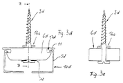
- Fig.3d and 3e is a fastening part 6d with the screw 3d fixed counter plate 16a shown.
- Fig.3e represents the section A-A according to Fig.3d through the fastening part
- This fastening part 6d is a stable frame - for example made of metal - through which the screw 3d protrudes.
- the profile 5d on the resilient leg 10d on the Fastening part are snapped on, the edge regions 11 in corresponding recesses 17d on the fastening part 6d intervene and thus the profile strip on the fastening part in determine its altitude, the displaceability of the Profile bar largely preserved in its longitudinal direction.
- An elastically flexible intermediate piece 18- if necessary Shape of a rubber washer - takes light bar movements balancing on
- the fasteners can be made of different materials be like wood, plastic or also - as is especially the case with the formation according to Fig.3c is suggested - made of metal.
Landscapes
- Engineering & Computer Science (AREA)
- Architecture (AREA)
- Civil Engineering (AREA)
- Structural Engineering (AREA)
- Connection Of Plates (AREA)
- Joining Of Building Structures In Genera (AREA)
- Finishing Walls (AREA)
Applications Claiming Priority (2)
| Application Number | Priority Date | Filing Date | Title |
|---|---|---|---|
| AT89498 | 1998-05-25 | ||
| AT89498A AT406174B (de) | 1998-05-25 | 1998-05-25 | Befestigungsteil für profile |
Publications (2)
| Publication Number | Publication Date |
|---|---|
| EP0960988A2 true EP0960988A2 (fr) | 1999-12-01 |
| EP0960988A3 EP0960988A3 (fr) | 2001-02-07 |
Family
ID=3502285
Family Applications (1)
| Application Number | Title | Priority Date | Filing Date |
|---|---|---|---|
| EP99109976A Withdrawn EP0960988A3 (fr) | 1998-05-25 | 1999-05-21 | Eléments de fixation pour profilés |
Country Status (4)
| Country | Link |
|---|---|
| EP (1) | EP0960988A3 (fr) |
| AT (1) | AT406174B (fr) |
| CH (1) | CH690554A5 (fr) |
| DE (1) | DE29908949U1 (fr) |
Cited By (1)
| Publication number | Priority date | Publication date | Assignee | Title |
|---|---|---|---|---|
| IT201900017480A1 (it) * | 2019-09-30 | 2021-03-30 | Alberto Noventa | Dispositivo, sistema e metodo di fissaggio per profili metallici di pareti in cartongesso |
Citations (1)
| Publication number | Priority date | Publication date | Assignee | Title |
|---|---|---|---|---|
| EP0442243A1 (fr) | 1990-02-13 | 1991-08-21 | Lanz Oensingen Ag | Dispositif de suspension et d'assemblage |
Family Cites Families (7)
| Publication number | Priority date | Publication date | Assignee | Title |
|---|---|---|---|---|
| DE2363908A1 (de) * | 1973-12-21 | 1975-06-26 | Gruenzweig Hartmann Glasfaser | Traggerippe fuer unterdecken |
| DE2652481A1 (de) * | 1976-11-18 | 1978-05-24 | Joachim Seiffert | Abhaengeelement fuer ein traggerippe zur halterung von zwischendeckenelementen |
| DE3717502A1 (de) * | 1987-05-23 | 1988-12-08 | Hartmut Semar | Universalabhaenger fuer decken- und dachschraegenabhaengungen |
| FR2671361B1 (fr) * | 1991-01-04 | 1998-09-18 | Placoplatre Sa | Suspente articulee. |
| GB2263117B (en) * | 1992-01-11 | 1995-07-12 | Victaulic Plc | Floor deck fixing device |
| DE29617249U1 (de) * | 1996-10-04 | 1997-02-06 | Richter-System GmbH & Co KG, 64347 Griesheim | Abhänger für CD-Schienen |
| DE29619956U1 (de) * | 1996-11-16 | 1997-12-11 | Erl, Klaus, 33330 Gütersloh | Vorrichtung zur Befestigung von Profilen |
-
1998
- 1998-05-25 AT AT89498A patent/AT406174B/de active
-
1999
- 1999-05-18 CH CH93399A patent/CH690554A5/de not_active IP Right Cessation
- 1999-05-21 DE DE29908949U patent/DE29908949U1/de not_active Expired - Lifetime
- 1999-05-21 EP EP99109976A patent/EP0960988A3/fr not_active Withdrawn
Patent Citations (1)
| Publication number | Priority date | Publication date | Assignee | Title |
|---|---|---|---|---|
| EP0442243A1 (fr) | 1990-02-13 | 1991-08-21 | Lanz Oensingen Ag | Dispositif de suspension et d'assemblage |
Cited By (1)
| Publication number | Priority date | Publication date | Assignee | Title |
|---|---|---|---|---|
| IT201900017480A1 (it) * | 2019-09-30 | 2021-03-30 | Alberto Noventa | Dispositivo, sistema e metodo di fissaggio per profili metallici di pareti in cartongesso |
Also Published As
| Publication number | Publication date |
|---|---|
| ATA89498A (de) | 1999-07-15 |
| AT406174B (de) | 2000-03-27 |
| DE29908949U1 (de) | 1999-08-26 |
| EP0960988A3 (fr) | 2001-02-07 |
| CH690554A5 (de) | 2000-10-13 |
Similar Documents
| Publication | Publication Date | Title |
|---|---|---|
| EP0683287B1 (fr) | Rail profilé de fixation d'objets plats | |
| EP3594427B1 (fr) | Système et procédé de fixation d'éléments de façade | |
| EP0180837B1 (fr) | Jeu de pièces séparées pour un dispositif de fixation de murs rideaux | |
| DE202009011708U1 (de) | Befestigungselement | |
| CH679874A5 (fr) | ||
| CH713372A1 (de) | System und Verfahren zur Befestigung von Fassadenelementen. | |
| EP0010694B1 (fr) | Revêtement pour murs ou plafonds | |
| DE2510949A1 (de) | Trennwand zum einbau in gebaeude | |
| DE10134396C1 (de) | Bausatz zum Einsetzen eines Wandelementes in eine Wandöffnung einer doppelschaligen Ständerwand | |
| AT406174B (de) | Befestigungsteil für profile | |
| EP0025208A2 (fr) | Elément de liaison pour le montage thermiquement et/ou acoustiquement isolant de panneaux de mur-rideaux, plaques ou éléments de construction analogues, respectivement organes de fixation pour de tels éléments de construction | |
| EP1518482A2 (fr) | Dispositif de suspension pour un placard le long d'un mur | |
| EP1201841A1 (fr) | Suspente pour profilés en C | |
| CH598448A5 (en) | Support structure for wall covering plates | |
| DE9311177U1 (de) | Vorrichtung zur Befestigung von Platten | |
| DE19930918C2 (de) | Verkleidungssystem für eine Wanne, vorzugsweise Badewanne | |
| EP0761904A1 (fr) | Système de montage pour panneaux | |
| DE2927969A1 (de) | Bauelementensatz zur verkleidung von decken, waenden o.dgl. | |
| DE3509997C2 (fr) | ||
| DE4204706A1 (de) | Haltersystem fuer sockelleisten zum fixieren und abdecken von heizkoerperanbindeleitungen hinter einer speziellen sockelleiste | |
| DE2806872A1 (de) | Fassadenunterkonstruktion | |
| DE29717928U1 (de) | Befestigungssystem zur Montage von Decken- und Wandverkleidungen | |
| DE2827148A1 (de) | Bausatz zur halterung von vertikalen tragprofilen mit gleitpunkt und festpunkt zur befestigung grossflaechiger plattenfoermig ausgebildeter gegenstaende an gebaeuden | |
| EP1627972B1 (fr) | Panneau de plafond et système de plafond | |
| WO2003040484A2 (fr) | Revetement mural |
Legal Events
| Date | Code | Title | Description |
|---|---|---|---|
| PUAI | Public reference made under article 153(3) epc to a published international application that has entered the european phase |
Free format text: ORIGINAL CODE: 0009012 |
|
| AK | Designated contracting states |
Kind code of ref document: A2 Designated state(s): AT BE CH CY DE DK ES FI FR GB GR IE IT LI LU MC NL PT SE |
|
| AX | Request for extension of the european patent |
Free format text: AL;LT;LV;MK;RO;SI |
|
| PUAL | Search report despatched |
Free format text: ORIGINAL CODE: 0009013 |
|
| AK | Designated contracting states |
Kind code of ref document: A3 Designated state(s): AT BE CH CY DE DK ES FI FR GB GR IE IT LI LU MC NL PT SE |
|
| AX | Request for extension of the european patent |
Free format text: AL;LT;LV;MK;RO;SI |
|
| AKX | Designation fees paid | ||
| STAA | Information on the status of an ep patent application or granted ep patent |
Free format text: STATUS: THE APPLICATION IS DEEMED TO BE WITHDRAWN |
|
| 18D | Application deemed to be withdrawn |
Effective date: 20010808 |
|
| REG | Reference to a national code |
Ref country code: DE Ref legal event code: 8566 |