EP0961009A2 - Profil de rotor à vis conjugué - Google Patents
Profil de rotor à vis conjugué Download PDFInfo
- Publication number
- EP0961009A2 EP0961009A2 EP99630043A EP99630043A EP0961009A2 EP 0961009 A2 EP0961009 A2 EP 0961009A2 EP 99630043 A EP99630043 A EP 99630043A EP 99630043 A EP99630043 A EP 99630043A EP 0961009 A2 EP0961009 A2 EP 0961009A2
- Authority
- EP
- European Patent Office
- Prior art keywords
- rotor
- female
- segment
- male
- point
- Prior art date
- Legal status (The legal status is an assumption and is not a legal conclusion. Google has not performed a legal analysis and makes no representation as to the accuracy of the status listed.)
- Granted
Links
- 238000007789 sealing Methods 0.000 claims description 4
- 230000008901 benefit Effects 0.000 description 11
- 238000004519 manufacturing process Methods 0.000 description 6
- 238000000034 method Methods 0.000 description 4
- 238000003754 machining Methods 0.000 description 3
- 238000005520 cutting process Methods 0.000 description 2
- 230000008030 elimination Effects 0.000 description 2
- 238000003379 elimination reaction Methods 0.000 description 2
- 238000007689 inspection Methods 0.000 description 2
- 230000004048 modification Effects 0.000 description 2
- 238000012986 modification Methods 0.000 description 2
- 230000009467 reduction Effects 0.000 description 2
- 230000005540 biological transmission Effects 0.000 description 1
- 230000008859 change Effects 0.000 description 1
- 230000007423 decrease Effects 0.000 description 1
- 230000001419 dependent effect Effects 0.000 description 1
- 239000012530 fluid Substances 0.000 description 1
- 238000000227 grinding Methods 0.000 description 1
- 238000003801 milling Methods 0.000 description 1
- 238000005096 rolling process Methods 0.000 description 1
- 230000007704 transition Effects 0.000 description 1
Images


Classifications
-
- F—MECHANICAL ENGINEERING; LIGHTING; HEATING; WEAPONS; BLASTING
- F04—POSITIVE - DISPLACEMENT MACHINES FOR LIQUIDS; PUMPS FOR LIQUIDS OR ELASTIC FLUIDS
- F04C—ROTARY-PISTON, OR OSCILLATING-PISTON, POSITIVE-DISPLACEMENT MACHINES FOR LIQUIDS; ROTARY-PISTON, OR OSCILLATING-PISTON, POSITIVE-DISPLACEMENT PUMPS
- F04C18/00—Rotary-piston pumps specially adapted for elastic fluids
- F04C18/08—Rotary-piston pumps specially adapted for elastic fluids of intermeshing-engagement type, i.e. with engagement of co-operating members similar to that of toothed gearing
-
- F—MECHANICAL ENGINEERING; LIGHTING; HEATING; WEAPONS; BLASTING
- F01—MACHINES OR ENGINES IN GENERAL; ENGINE PLANTS IN GENERAL; STEAM ENGINES
- F01C—ROTARY-PISTON OR OSCILLATING-PISTON MACHINES OR ENGINES
- F01C1/00—Rotary-piston machines or engines
- F01C1/08—Rotary-piston machines or engines of intermeshing engagement type, i.e. with engagement of co- operating members similar to that of toothed gearing
- F01C1/082—Details specially related to intermeshing engagement type machines or engines
- F01C1/084—Toothed wheels
Definitions
- the conjugate pair must meet the sealing requirements as the line contact advances along the rotor profile in the driving/driven coaction and as the rotor tips and end faces coact with the enclosing casing.
- This line contact follows the perimeters of the rotor profiles and is therefore at a varying tangential speed and has significant radial components.
- the shape and cross section of the spiral grooves must meet requirements for ease of manufacture and cutting tool life.
- One problem associated with conventional screw rotor designs is that the pressure angle and lobe thickness are interrelated. It is desirable to minimize the pressure angle, the angle of contact between the rotors in the contact zone near or at the pitch circle, to provide reduced contact loading. However, the reducing of the pressure angle has an attendant undesirable reduction in lobe thickness such that conventional designs represent a compromise between desired pressure angle and desired lobe thickness.
- the present invention is directed to an improved configuration for a conjugate pair of screw rotors.
- benefits provided by the present invention are: reduced viscous drag through the use of a departure angle; strengthened female lobes by controlling thickness along the pitch circle; opened root of male rotor to enhance manufacturability and tool life; a tortuous flow path for gas leaking from a high pressure thread; better control of root diameter; and control of the pressure angle independently of the other variables.
- the point of tangency of the tip circle of the male rotor and the root circle of the female rotor is used as a starting point in generating the series of curves defining the male and female conjugate rotor profiles. Additionally, the pressure angle is independent of the female lobe thickness.
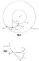
- the numeral 10 generally indicates a screw machine such as a screw compressor.
- Screw machine 10 has a casing 12 with overlapping bores 12-1 and 12-2 located therein.
- Female rotor 14 has a pitch circle, P F , and is located in bore 12-1.
- Male rotor 16 has a pitch circle, P M , and is located in bore 12-2.
- the axes indicated by points A and B are perpendicular to the plane of Figure 1 and are parallel to each other and are separated by a distance equal to the sum of the radius, R F , of the pitch circle, P F , of female rotor 14 and the radius, R M , of the pitch circle, P M , of male rotor 16.
- the axis indicated by point A is the axis of rotation of female rotor 14 and the center of bore 12-1 whose diameter generally corresponds to the diameter of the tip circle, T F , of female rotor 14.
- the axis indicated by point B is the axis of rotation of male rotor 16 and the center of bore 12-2 whose diameter generally corresponds to the diameter of the tip circle, T M , of male rotor 16.
- female rotor 14 has six lands, 14-1, separated by six grooves, 14-2, while male rotor 16 has five lands, 16-1, separated by five grooves 16-2. Accordingly, the rotational speed of rotor 16 will be 6/5 or 120% of that of rotor 14.
- Either the female rotor 14 or the male rotor 16 may be connected to a prime mover (not illustrated) and serve as the driving rotor. Other combinations of the number of female and male lands and grooves may also be used.
- Curve F 2 -F 3 is a circular arc on female rotor 14 and extends from point F 2 to the pitch circle P F .
- the center of curve F 2 -F 3 is positioned such that curve F 2 -F 3 both intersects curve F 1 -F 2 and is tangent to curve F 1 -F 2 at the point of intersection.
- the radius of curve F 2 -F 3 is adjusted to provide a desired balance between minimum blow hole area, as it affects the angle at which curve F 3 -F 4 intersects the pitch circle P F , described below, and ease of manufacturing since tool life decreases with a reduction in the radius of curve F 2 -F 3 .
- Curve F 2 -F 3 generates curve M 1 -M 2 on male rotor 16.
- point M 1 generates curve F 1 -F 2 so that F 2 is a common point with point M 1 at one point in the rotation of the rotors.
- Curve M 1 -M 2 represents the path swept out on male rotor 16 by curve F 2 -F 3 as contact advances from F 2 to F 3 while both of rotors 14 and 16 are rotating at the same pitch circle velocity.
- the curve F 3 -F 4 is a circular arc on female rotor 14 and its length or angular range is adjusted such that the male portion it generates, M 2 -M 3 , falls inside the pitch circle, P M , of male rotor 16.
- the center of curve F 3 -F 4 is positioned such that curve F 3 -F 4 both intersects curve F 2 -F 3 and is tangent to curve F 2 -F 3 at the point of intersection.
- Curve F 3 -F 4 influences the blow hole area, which is a leakage area defined by the cusp between bores 12-1 and 12-2 and rotors 14 and 16, and by minimizing the blow hole area, the leakage area, and therefore the leakage, is reduced which helps to improve the efficiency of screw machine 10.
- the radius of curve F 3 -F 4 is adjusted to provide a desired balance between minimum blow hole area and ease of manufacturing.
- Curve M 2 -M 3 is generated by curve F 3 -F 4 on the female rotor 14 and represents the clearance path swept out on male rotor 16 by curve F 3 -F 4 as contact advances from F 3 to F 4 while both of rotors 14 and 16 are rotating at the same pitch circle velocity.
- the curve F 4 -F 5 on female rotor 14 is a circular arc extending from point F 4 to its intersection with the tip circle T F (bore 12-1) at point F 5 .
- the radius and position of curve F 4 -F 5 is adjusted so that curve F 4 -F 5 is both coincident with and tangent to curve F 3 -F 4 at the point of intersection, F 4 , and so that it is tangent to the tip circle T F (bore 12-1) at point F 5 .
- Curve M 3 -M 4 on the male rotor is generated by curve F 4 -F 5 and represents the path swept out on male rotor 16 by curve F 4 -F 5 as contact advances from M 3 to M 4 while both of rotors 14 and 16 are rotating at the same pitch circle velocity.
- Curve F 5 -F 5 ' is a circular arc extending along the tip circle T F (bore 12-1) of female rotor 14. Curve F 5 -F 5 ' generates curve M 4 - M 5 as contact advances from F 5 to F 5 ' while both of rotors 14 and 16 are rotating at the same pitch circle velocity. Since curve F 5 - F 5 ' is a circular arc on the tip circle T F (bore 12-1) of the female rotor 14 and is thus centered on the female rotor center A, the resulting curve M 4 - M 5 is also a circular arc which is centered on the male rotor center B and which is the root circle R MR of male rotor 16. These qualities of M 4 - M 5 make it particularly suited for easy generation and inspection and provides better control of the male root for manufacturability.
- Points F 5 " and M 5 ' correspond to points F 5 ' and M 5 , respectively, located on an adjacent rotor lobe face and will be used as starting points for describing the other portions of the profiles of rotors 14 and 16.
- Straight line, or curve of infinite radius, F 5 "-F 6 extends from F 5 " on the tip of female rotor 14 at an angle, ⁇ 1 , with respect to a tangent at female tip circle T F (bore 12-1) at F 5 ".
- Line F 5 "-F 6 extends to a point short of the female pitch circle P F .
- the angle ⁇ 1 is the female rotor departure angle and it provides the benefit of reducing viscous drag.
- Curve M 5 '-M 6 on male rotor 16 is generated by line F 5 "-F 6 and represents the path swept out on male rotor 16 by line F 5 "-F 6 as contact advances from M 5 ' to M 6 while both of rotors 14 and 16 are rotating at the same pitch circle velocity.
- Curve F 6 -F 7 is a circular arc on female rotor 14.
- Line F 5 "-F 6 and curve F 6 -F 7 coact to: (1) control the thickness, t, of the lobes of female rotor 14 as measured along the pitch circle, P F , and which is controlled to maintain stiffness of the female lobe tip 14-1 to reduce deflection during machining; (2) to provide sufficient room at the base 16-2 of the male lobe so that a large, strong cutting tool may be used to improve the accuracy and speed of machining; and (3) to make the leak path more tortuous.
- Curve M 6 -M 7 on male rotor 16 is generated by curve F 6 -F 7 and represents the path swept out on male rotor 16 by curve F 6 -F 7 as contact advances from M 6 to M 7 while both of rotors 14 and 16 are rotating at the same pitch circle velocity.
- Curve M 7 -M 8 on male rotor 16 is an involute of a circle at the desired pressure angle.
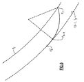
- the male pitch circle, P M , and female pitch circle, P F meet at a common point called the pitch point and have a common tangent at the pitch point.
- a common normal can be drawn between the contact point and the pitchpoint. The angle between this common normal at the contact point and the common tangent at the pitchpoint is called pressure angle.
- Curve F 7 -F 8 on female rotor 14 is also an involute of a circle at the desired pressure angle.
- the involute base circle is smaller than but proportional to the pitch circles P F and P M of the female rotor 14 and the male rotor 16, respectively.
- P F and P M are inherently conjugate and one surface need not be generated by the other.
- Points F 7 and F 8 are not on the same side of pitch circle, P F , but one of the points can be located on the pitch circle.
- the transmission of torque between the driving and driven rotors occurs at, or near, the pitch circle with some sliding but primarily with rolling contact between the rotors.
- Point F 7 has been illustrated as located on pitch circle P F .
- Curve M 9 -M 1 is a circular arc on the tip circle T M (bore 12-2) of male rotor 16.
- Curve F 9 -F 1 on female rotor 14 is generated by curve M 9 -M 1 and represents the path swept out on female rotor 14 by curve M 9 -M 1 as line contact advances from F 9 to F 1 while both rotors 14 and 16 are rotating at the same pitch circle velocity.
- curve M 9 -M 1 is a circular arc on the tip circle T M (bore 12-2) of male rotor 16 and is thus centered on the male rotor center B
- the resulting curve F 9 -F 1 is also a circular arc which is centered on the female rotor center A and which is the root circle R FR of the female rotor 14.
- the curve M 8 -M 9 , on male rotor 16 is a curve of variable length and radius which bridges the gap between points M 8 and M 9 , while approaching point M 9 at departure angle ⁇ 2 with respect to a tangent at tip circle T M (bore 12-2) of male rotor 16.
- Curve M 8 -M 9 may be a generalized involute or made up of two or more curves such as arcs of circles with different radii.
- Curve F 8 -F 9 on female rotor 14 is generated by curve M 8 -M 9 , and represents the path swept out on female rotor 14 by curve M 8 -M 9 as line contact advances from F 8 to F 9 , while both of rotors 14 and 16 are rotating at the same pitch circle velocity.
- the curve F 8 -F 9 on female rotor 14 may be a curve of variable length and radius which bridges the gap between points F 8 and F 9 while approaching point F 9 at an angle which will control departure angle ⁇ 2 with respect to a tangent at tip circle T M (bore 12-2) of male rotor 16 at point M 9 .
- Curve F 8 -F 9 may be a generalized involute or made up of two or more curves such as arcs of circles with different radii.
- Curve M 8 -M 9 on male rotor 16 is generated by alternative curve F 8 -F 9 and represents the path swept out on male rotor 16 by alternative curve F 8 -F 9 as line contact advances from M 8 to M 9 while both rotors 14 and 16 are rotating at the same pitch velocity.
- the curves F 5 "-F 6 , M 5 '-M 6 , F 6 -F 7 , M 6 -M 7 , M 8 -M 9 , and F 8 -F 9 coact to provide control of the pressure angle independently of other profile variables such as female and male departure angles ⁇ 1 and ⁇ 2 , respectively, and the female lobe thickness, t, among others.
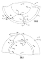
- points W and X would correspond to points F 5 and F 5 ' of female rotor 14 and points M 1 and M 9 of male rotor 16, respectively.
- the departure angle ⁇ 1 for female rotor 14 and ⁇ 2 for male rotor 16 is located between a tangent to curve W-X at point X and the departure segment S which is the portion of rotor 14 or 16 starting at point X and corresponding to line F 5 "-F 6 on female rotor 14 and curve M 8 -M 9 on male rotor 16. It will be noted that departure segment S moves rapidly away from the bore which will be 12-1 for rotor 14 and 12-2 for rotor 16.
- oil film 100 is dependent upon a close distance between adjacent parts, its length is reduced and restricted essentially to the region of small clearance which essentially corresponds to the surface defined between W and X and a little past X.
- the reduced length of oil film 100 results in a reduced viscous shear stress area and thus reduced overall drag.
- Departure segment S' has a PRIOR ART configuration and starts essentially tangent to, and for considerable distance remains close to, the rotor bore 12-1', 12-2'.
- the oil film 100' which develops is much longer than oil film 100 and results in a greater viscous drag as the rotor tip moves relative to the bore as compared to the configuration of Figure 4.
- the present invention permits control of the pressure angle independently of other profile variables such as female and male departure angles ⁇ 1 and ⁇ 2 , respectively, and the female lobe thickness, t, among others. Accordingly, the rotor profiles described above may be modified in order to achieve a desired design feature.
- Segment F 5 "-F 6 of Figure 2 is described above as a straight line or a curve of infinite radius. In reality, taking manufacturing tolerances and the length of F 5 "-F 6 into account, there would be no practical difference if F 5 "-F 6 is a straight line or a curved segment where the radius is very large, and there would be no perceived difference in the drawings in the absence of distortion at a very greatly magnified scale. Segment F 5 "-F 6 becomes a point where there is tangency with the tip circle at F 5 " and where ⁇ 1 becomes 0°.
- Figure 7 illustrates a second modified female rotor profile. Specifically, points F 5 " and F 7 are connected through three curved segments, rather than two segments. Segment F 5 "-F 6-2 is a small radius portion intersecting the female rotor tip circle T F (bore 12-1). Segment F 6-2 -F 6-3 is a large radius segment and segment F 6-3 -F 7 is a small radius segment.
- the angle ⁇ 1 is the female rotor departure angle and is measured between a tangent to point F 6-2 and the female rotor tip circle T F (bore 12-1). Segments F 5 "-F 6-2 , F 6-2 -F 6-3 and F 6-3 -F 7 will generate modified segments corresponding to the portion between M 5 ' and M 7 on male rotor 16.
- the advantage of the embodiment of Figure 7 is the elimination of the sharp corner at F 5 " which otherwise might be difficult to produce with certain manufacturing processes such as finish milling or grinding of the lobes and tip diameter in a single operation.
- Figure 8 illustrates a third modified female rotor profile. Specifically, points F 5 " and F 7 are connected through three curved segments. Segment F 5 "-F 6-4 is a large radius portion intersecting the female rotor tip circle T F (bore 12-1). Segment F 6-4 -F 6-5 is a curved segment having a smaller radius than segment F 5 "-F 6-4 . Segment F 6-5 -F 7 is a curved segment having a smaller radius than segment F 6-4 -F 6-5 . Segments F 5 "-F 6-4 , F 6-4 -F 6-5 and F 6-5 -F 7 will generate modified segments corresponding to the portion between M 5 ' and M 7 on male rotor 16.
- the advantage of the embodiment of Figure 8 is the increased flexibility in the independent selection of female lobe thickness, pressure angle and the radius of segments F 6-4 -F 6-5 and F 6-5 - F 7 which replace segment F 6 -F 7 in the Figure 2 embodiment and which may be restricted in certain desired ranges based on manufacturing requirements.
- Figure 9 illustrates a fourth modified female rotor profile. Specifically, points F 5 " and F 7 are connected through a single varying radius curve, such as an involute, which reduces in radius in going from point F 5 " to point F 7 . Segment F 5 "-F 7 will generate a modified segment corresponding to the portion between M 5 ' and M 7 on male rotor 16.
- the advantage of the embodiment of Figure 9 is the extension of the width of the contact band where a constant pressure angle is maintained.
- curve M 8 -M 9 or curve F 8 -F 9 is made up of two or more curves, one of said curves may be located on a portion of curve M 8 -M 9 and another of said curves may be located on curve F 8 -F 9 , both of said curves being located so as not to be conjugate with each other.
- Figure 10 illustrates a fifth modified female rotor profile. Specifically, points F 8 and F 9 are connected through two curves. The two curves are F 8 - F 8 ' and F 8 ' - F 9 which are each arcs of circles. Segments F 8 - F 8 ' and F 8 ' - F 9 will coact to generate a modified segment corresponding to segment M 8 - M 9 on male rotor 16.
- the advantage of the embodiment of Figure 10 is an alternate method of generating curves F 8 -F 9 and M 8 -M 9 of Figures 2 and 3, respectively, by substituting simplified arcs of circles on the female rotor in place of the more complex generalized involute.
- Figure 11 illustrates a sixth modified female rotor profile. Specifically, points F 8 and F 9 are connected through two curves. The two curves are F 8 - F 8 " which is a curve of continuously varying radius, such as an involute, and F 8 " - F 9 which is an arc of a circle. Segments F 8 -F 8" and F 8" -F 9 coact to generate a modified segment M 8 -M 9 on male rotor 16.
- the advantage of the embodiment of Figure 11 is an alternate method of generating curves F 8 -F 9 and M 8 -M 9 of Figures 2 and 3 by substituting a simplified arc of a circle and a lower order involute on the female rotor in place of the more complex generalized involute.
- Figure 12 illustrates a first modified male rotor profile. Specifically, points M 8 and M 9 are connected through two curves. Curves M 8 - M 8 ' and M 8 ' - M 9 are each arcs of circles tangent at their common point M 8 '.
- the advantage of the embodiment of Figure 12 is an alternate method of generating curves F 8 -F 9 and M 8 -M 9 of Figures 2 and 3 by substituting simplified arcs of circles on the male rotor in place of the more complex generalized involute.
- Figure 13 illustrates a second modified male rotor profile. Specifically, points M 8 and M 9 are connected through two curves. Curve M 8 and M 8 " is an arc of a circle and curve M 8 " - M 9 is a curve of continuously varying radius such as an involute. The two curves are tangent at their common point M 8 ".
- the advantage of the embodiment of Figure 13 is an alternate method of generating curves F 8 -F 9 and M 8 -M 9 of Figures 2 and 3 by substituting a simplified arc of a circle and a lower order of involute on the male rotor in place of the more complex generalized involute.
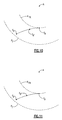
- Figures 14 and 15 depict conjugate segments on a female and male rotor, respectively.
- the Figure 14 modification differs from the Figure 2 embodiment in that points F 7 and F 9 are connected through a single curve of continuously varying radius, such as a generalized involute.
- the Figure 15 modification differs from the Figure 3 embodiment in that points M 7 and M 9 are connected through a single curve of continuously varying radius, such as a generalized involute.
- the advantage of the embodiments of Figures 14 and 15 is the elimination of the transition at the points F 8 and M 8 and the associated sudden change in radius of curvature which in some cases might otherwise add complexity to the design.
Landscapes
- Engineering & Computer Science (AREA)
- Mechanical Engineering (AREA)
- General Engineering & Computer Science (AREA)
- Applications Or Details Of Rotary Compressors (AREA)
- Rotary Pumps (AREA)
- Credit Cards Or The Like (AREA)
- Spinning Or Twisting Of Yarns (AREA)
Applications Claiming Priority (2)
| Application Number | Priority Date | Filing Date | Title |
|---|---|---|---|
| US09/087,576 US6139299A (en) | 1998-05-29 | 1998-05-29 | Conjugate screw rotor profile |
| US87576 | 1998-05-29 |
Publications (3)
| Publication Number | Publication Date |
|---|---|
| EP0961009A2 true EP0961009A2 (fr) | 1999-12-01 |
| EP0961009A3 EP0961009A3 (fr) | 2000-09-06 |
| EP0961009B1 EP0961009B1 (fr) | 2006-03-15 |
Family
ID=22205994
Family Applications (1)
| Application Number | Title | Priority Date | Filing Date |
|---|---|---|---|
| EP99630043A Expired - Lifetime EP0961009B1 (fr) | 1998-05-29 | 1999-05-07 | Profil de rotor à vis conjugué |
Country Status (9)
| Country | Link |
|---|---|
| US (1) | US6139299A (fr) |
| EP (1) | EP0961009B1 (fr) |
| JP (1) | JP3258641B2 (fr) |
| KR (1) | KR20000011273A (fr) |
| CN (1) | CN1138924C (fr) |
| AU (1) | AU768287B2 (fr) |
| DE (1) | DE69930367T2 (fr) |
| ES (1) | ES2257023T3 (fr) |
| TW (1) | TW418287B (fr) |
Cited By (3)
| Publication number | Priority date | Publication date | Assignee | Title |
|---|---|---|---|---|
| AU738697B2 (en) * | 1998-12-10 | 2001-09-27 | Carrier Corporation | Clearance distribution to reduce the leakage area |
| EP1264988A3 (fr) * | 2001-06-07 | 2003-05-14 | Carrier Corporation | Bout de rotor hélicoidal |
| CN113833655A (zh) * | 2021-11-02 | 2021-12-24 | 杭州久益机械股份有限公司 | 一种螺杆真空泵转子及螺杆真空泵 |
Families Citing this family (8)
| Publication number | Priority date | Publication date | Assignee | Title |
|---|---|---|---|---|
| EP2088284A1 (fr) | 2008-02-11 | 2009-08-12 | Liung Feng Industrial Co Ltd | Procédé pour la conception de rotors de type lobe |
| GB2501302B (en) * | 2012-04-19 | 2016-08-31 | The City Univ | Reduced noise screw machines |
| CN105443380B (zh) * | 2015-12-22 | 2017-08-25 | 上海齐耀螺杆机械有限公司 | 双螺杆压缩机转子的齿型 |
| CN106401958B (zh) * | 2016-12-08 | 2018-08-10 | 合肥工业大学 | 一种螺杆真空泵转子型线 |
| CN111456940A (zh) * | 2020-05-15 | 2020-07-28 | 萨震压缩机(上海)有限公司 | 节能螺杆型线 |
| CN112746966B (zh) * | 2021-01-25 | 2025-02-25 | 宿迁学院 | 一种具有内直共轭和更大形状系数的凸转子轮廓 |
| CN114658656B (zh) * | 2022-03-04 | 2024-05-24 | 中科仪(南通)半导体设备有限责任公司 | 一种用于干式真空泵的直爪式转子及其设计方法 |
| CN114837936B (zh) * | 2022-06-09 | 2024-05-03 | 中国计量大学 | 一种耐磨损弹性体转子泵型线及其转子泵 |
Family Cites Families (9)
| Publication number | Priority date | Publication date | Assignee | Title |
|---|---|---|---|---|
| US32568A (en) * | 1861-06-18 | kelley | ||
| SE312394B (fr) * | 1965-05-10 | 1969-07-14 | A Lysholm | |
| GB1480333A (en) * | 1973-07-05 | 1977-07-20 | Svenska Rotor Maskiner Ab | Screw rotor machines |
| IN157732B (fr) | 1981-02-06 | 1986-05-24 | Svenska Rotor Maskiner Ab | |
| US4527967A (en) * | 1984-08-31 | 1985-07-09 | Dunham-Bush, Inc. | Screw rotor machine with specific tooth profile |
| JP2620785B2 (ja) | 1987-06-03 | 1997-06-18 | 住友重機械工業株式会社 | スクリューロータの歯形設計方法 |
| US5207568A (en) * | 1991-05-15 | 1993-05-04 | Vilter Manufacturing Corporation | Rotary screw compressor and method for providing thrust bearing force compensation |
| JP3356468B2 (ja) * | 1992-10-09 | 2002-12-16 | 株式会社前川製作所 | スクリューロータ |
| JP6041238B2 (ja) | 2012-08-10 | 2016-12-07 | 国立研究開発法人水産研究・教育機構 | ブリ細菌性溶血性黄疸の病原体抗原ポリペプチド、及びこれを含む水産用ワクチン |
-
1998
- 1998-05-29 US US09/087,576 patent/US6139299A/en not_active Expired - Lifetime
-
1999
- 1999-04-20 TW TW088106292A patent/TW418287B/zh not_active IP Right Cessation
- 1999-05-07 EP EP99630043A patent/EP0961009B1/fr not_active Expired - Lifetime
- 1999-05-07 DE DE69930367T patent/DE69930367T2/de not_active Expired - Lifetime
- 1999-05-07 ES ES99630043T patent/ES2257023T3/es not_active Expired - Lifetime
- 1999-05-26 CN CNB991071018A patent/CN1138924C/zh not_active Expired - Fee Related
- 1999-05-28 JP JP14920099A patent/JP3258641B2/ja not_active Expired - Fee Related
- 1999-05-28 AU AU32350/99A patent/AU768287B2/en not_active Ceased
- 1999-05-28 KR KR1019990019550A patent/KR20000011273A/ko not_active Ceased
Non-Patent Citations (1)
| Title |
|---|
| None |
Cited By (3)
| Publication number | Priority date | Publication date | Assignee | Title |
|---|---|---|---|---|
| AU738697B2 (en) * | 1998-12-10 | 2001-09-27 | Carrier Corporation | Clearance distribution to reduce the leakage area |
| EP1264988A3 (fr) * | 2001-06-07 | 2003-05-14 | Carrier Corporation | Bout de rotor hélicoidal |
| CN113833655A (zh) * | 2021-11-02 | 2021-12-24 | 杭州久益机械股份有限公司 | 一种螺杆真空泵转子及螺杆真空泵 |
Also Published As
| Publication number | Publication date |
|---|---|
| EP0961009B1 (fr) | 2006-03-15 |
| US6139299A (en) | 2000-10-31 |
| TW418287B (en) | 2001-01-11 |
| ES2257023T3 (es) | 2006-07-16 |
| AU768287B2 (en) | 2003-12-04 |
| CN1138924C (zh) | 2004-02-18 |
| EP0961009A3 (fr) | 2000-09-06 |
| DE69930367T2 (de) | 2006-10-19 |
| AU3235099A (en) | 1999-12-09 |
| DE69930367D1 (de) | 2006-05-11 |
| CN1240885A (zh) | 2000-01-12 |
| JP3258641B2 (ja) | 2002-02-18 |
| KR20000011273A (ko) | 2000-02-25 |
| JPH11351170A (ja) | 1999-12-21 |
Similar Documents
| Publication | Publication Date | Title |
|---|---|---|
| JP4243498B2 (ja) | リング歯車マシンクリアランス | |
| EP0158514B1 (fr) | Rotors hélicoidaux | |
| USRE32568E (en) | Screw rotor machine and rotor profile therefor | |
| US20220136504A1 (en) | Rotor pair for a compression block of a screw machine | |
| EP0174081B1 (fr) | Compresseur ou machine à expansion à rotors hélicoidaux | |
| EP0961009B1 (fr) | Profil de rotor à vis conjugué | |
| KR910002727B1 (ko) | 양변위(positive-displacement) 회전장치 및 그 장치용의 로우터 | |
| JPH0127241B2 (fr) | ||
| US4401420A (en) | Male and female screw rotor assembly with specific tooth flanks | |
| EP1008755B1 (fr) | Machine à rotors à vis | |
| US5947713A (en) | Pair of co-operating screw rotors, a screw rotor and a rotary screw machine | |
| US9714572B2 (en) | Reduced noise screw machines | |
| JPH0226681B2 (fr) | ||
| AU2003257923B2 (en) | Conjugate screw rotor profile | |
| US4614484A (en) | Rotary screw compressor with specific tooth profile | |
| US7163387B2 (en) | Meshing helical rotors |
Legal Events
| Date | Code | Title | Description |
|---|---|---|---|
| PUAI | Public reference made under article 153(3) epc to a published international application that has entered the european phase |
Free format text: ORIGINAL CODE: 0009012 |
|
| AK | Designated contracting states |
Kind code of ref document: A2 Designated state(s): DE ES FR GB IT NL |
|
| AX | Request for extension of the european patent |
Free format text: AL;LT;LV;MK;RO;SI |
|
| PUAL | Search report despatched |
Free format text: ORIGINAL CODE: 0009013 |
|
| AK | Designated contracting states |
Kind code of ref document: A3 Designated state(s): AT BE CH CY DE DK ES FI FR GB GR IE IT LI LU MC NL PT SE |
|
| AX | Request for extension of the european patent |
Free format text: AL;LT;LV;MK;RO;SI |
|
| 17P | Request for examination filed |
Effective date: 20010210 |
|
| AKX | Designation fees paid |
Free format text: DE ES FR GB IT NL |
|
| 17Q | First examination report despatched |
Effective date: 20040218 |
|
| GRAP | Despatch of communication of intention to grant a patent |
Free format text: ORIGINAL CODE: EPIDOSNIGR1 |
|
| GRAS | Grant fee paid |
Free format text: ORIGINAL CODE: EPIDOSNIGR3 |
|
| GRAA | (expected) grant |
Free format text: ORIGINAL CODE: 0009210 |
|
| AK | Designated contracting states |
Kind code of ref document: B1 Designated state(s): DE ES FR GB IT NL |
|
| REG | Reference to a national code |
Ref country code: GB Ref legal event code: FG4D |
|
| REF | Corresponds to: |
Ref document number: 69930367 Country of ref document: DE Date of ref document: 20060511 Kind code of ref document: P |
|
| REG | Reference to a national code |
Ref country code: ES Ref legal event code: FG2A Ref document number: 2257023 Country of ref document: ES Kind code of ref document: T3 |
|
| ET | Fr: translation filed | ||
| RAP2 | Party data changed (patent owner data changed or rights of a patent transferred) |
Owner name: CARRIER CORPORATION |
|
| NLT2 | Nl: modifications (of names), taken from the european patent patent bulletin |
Owner name: CARRIER CORPORATION Effective date: 20061227 |
|
| PLBE | No opposition filed within time limit |
Free format text: ORIGINAL CODE: 0009261 |
|
| STAA | Information on the status of an ep patent application or granted ep patent |
Free format text: STATUS: NO OPPOSITION FILED WITHIN TIME LIMIT |
|
| PGFP | Annual fee paid to national office [announced via postgrant information from national office to epo] |
Ref country code: NL Payment date: 20070423 Year of fee payment: 9 |
|
| 26N | No opposition filed |
Effective date: 20061218 |
|
| PG25 | Lapsed in a contracting state [announced via postgrant information from national office to epo] |
Ref country code: NL Free format text: LAPSE BECAUSE OF NON-PAYMENT OF DUE FEES Effective date: 20081201 |
|
| PGFP | Annual fee paid to national office [announced via postgrant information from national office to epo] |
Ref country code: IT Payment date: 20120516 Year of fee payment: 14 |
|
| PG25 | Lapsed in a contracting state [announced via postgrant information from national office to epo] |
Ref country code: IT Free format text: LAPSE BECAUSE OF NON-PAYMENT OF DUE FEES Effective date: 20130507 |
|
| REG | Reference to a national code |
Ref country code: FR Ref legal event code: PLFP Year of fee payment: 18 |
|
| REG | Reference to a national code |
Ref country code: FR Ref legal event code: PLFP Year of fee payment: 19 |
|
| REG | Reference to a national code |
Ref country code: DE Ref legal event code: R082 Ref document number: 69930367 Country of ref document: DE Representative=s name: SCHMITT-NILSON SCHRAUD WAIBEL WOHLFROM PATENTA, DE |
|
| PGFP | Annual fee paid to national office [announced via postgrant information from national office to epo] |
Ref country code: FR Payment date: 20170421 Year of fee payment: 19 Ref country code: GB Payment date: 20170426 Year of fee payment: 19 Ref country code: DE Payment date: 20170420 Year of fee payment: 19 |
|
| PGFP | Annual fee paid to national office [announced via postgrant information from national office to epo] |
Ref country code: ES Payment date: 20170607 Year of fee payment: 19 |
|
| REG | Reference to a national code |
Ref country code: DE Ref legal event code: R119 Ref document number: 69930367 Country of ref document: DE |
|
| GBPC | Gb: european patent ceased through non-payment of renewal fee |
Effective date: 20180507 |
|
| PG25 | Lapsed in a contracting state [announced via postgrant information from national office to epo] |
Ref country code: FR Free format text: LAPSE BECAUSE OF NON-PAYMENT OF DUE FEES Effective date: 20180531 Ref country code: DE Free format text: LAPSE BECAUSE OF NON-PAYMENT OF DUE FEES Effective date: 20181201 Ref country code: GB Free format text: LAPSE BECAUSE OF NON-PAYMENT OF DUE FEES Effective date: 20180507 |
|
| REG | Reference to a national code |
Ref country code: ES Ref legal event code: FD2A Effective date: 20190913 |
|
| PG25 | Lapsed in a contracting state [announced via postgrant information from national office to epo] |
Ref country code: ES Free format text: LAPSE BECAUSE OF NON-PAYMENT OF DUE FEES Effective date: 20180508 |