EP0961068A1 - Rohrverbindungswerkzeug - Google Patents
Rohrverbindungswerkzeug Download PDFInfo
- Publication number
- EP0961068A1 EP0961068A1 EP99109943A EP99109943A EP0961068A1 EP 0961068 A1 EP0961068 A1 EP 0961068A1 EP 99109943 A EP99109943 A EP 99109943A EP 99109943 A EP99109943 A EP 99109943A EP 0961068 A1 EP0961068 A1 EP 0961068A1
- Authority
- EP
- European Patent Office
- Prior art keywords
- brackets
- crop
- fact
- machine
- fittings
- Prior art date
- Legal status (The legal status is an assumption and is not a legal conclusion. Google has not performed a legal analysis and makes no representation as to the accuracy of the status listed.)
- Granted
Links
- 230000008878 coupling Effects 0.000 claims abstract description 7
- 238000010168 coupling process Methods 0.000 claims abstract description 7
- 238000005859 coupling reaction Methods 0.000 claims abstract description 7
- 239000000463 material Substances 0.000 claims abstract description 4
- 238000003780 insertion Methods 0.000 claims abstract description 3
- 230000037431 insertion Effects 0.000 claims abstract description 3
- 239000004033 plastic Substances 0.000 claims abstract description 3
- 229920003023 plastic Polymers 0.000 claims abstract description 3
- 229920001971 elastomer Polymers 0.000 description 2
- 238000007789 sealing Methods 0.000 description 2
- 239000004698 Polyethylene Substances 0.000 description 1
- 238000004026 adhesive bonding Methods 0.000 description 1
- 239000000806 elastomer Substances 0.000 description 1
- 239000012530 fluid Substances 0.000 description 1
- 239000007788 liquid Substances 0.000 description 1
- -1 polyethylene Polymers 0.000 description 1
- 229920000573 polyethylene Polymers 0.000 description 1
- 230000000452 restraining effect Effects 0.000 description 1
Images

Classifications
-
- F—MECHANICAL ENGINEERING; LIGHTING; HEATING; WEAPONS; BLASTING
- F16—ENGINEERING ELEMENTS AND UNITS; GENERAL MEASURES FOR PRODUCING AND MAINTAINING EFFECTIVE FUNCTIONING OF MACHINES OR INSTALLATIONS; THERMAL INSULATION IN GENERAL
- F16L—PIPES; JOINTS OR FITTINGS FOR PIPES; SUPPORTS FOR PIPES, CABLES OR PROTECTIVE TUBING; MEANS FOR THERMAL INSULATION IN GENERAL
- F16L1/00—Laying or reclaiming pipes; Repairing or joining pipes on or under water
- F16L1/024—Laying or reclaiming pipes on land, e.g. above the ground
- F16L1/06—Accessories therefor, e.g. anchors
- F16L1/09—Accessories therefor, e.g. anchors for bringing two tubular members closer to each other
Definitions
- the present invention relates to a restrained coupling machine for crop-ends and/or fittings of pipe, particularly pipes which present a large diameter and are made of plastic material.
- the crop-ends/fitting of pipe which present a large diameter and are mostly made of polyethylene, are manufactured in crop-ends with a predetermined length, and are used to build mains, often underground, for liquids or fluids.
- crop-ends and fittings are provided, at one of their ends, with an oversized section portion which is able to receive a non-oversized end of another crop-end and/or fitting, so as to realise mains of the desired length. Therefore, these mains are built with a number of coupled crop-ends and/or fittings presenting their relevant ends restrained by each other.
- an annular gasket made of elastomer material or rubber is applied by means of glueing or it is fit to an expressly made seat.
- This gasket ensures the leak-proof sealing of the connection, on the other hand it makes the restrained coupling of the two pipes fitting very difficult.
- these pipes have a very large diameter, and their coupling and decoupling needs the strength of at least two people.
- One aim of the present invention is to realise a machine which is able to carry out this operation in a convenient way and without excessive exertion, and which eventually allows one person to do the whole operation by himself.
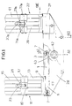
- number 1 indicates a rack provided at its relevant ends 3 and 5 with two couples of bearings 7, which have the function of support wheels and of translation.
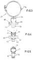
- One end of rack is integral with a support 9 on which an annular bracket 11, composed of two parts 13 and 15, is fixed.
- the two semi-annular parts are hinged to each other at one of their relevant ends by a hinge 17, meanwhile, they are provided with a coupling system at the other opposite end: the system is adjustable to clamp the pipe and/or the pipe-fitting, and, in the example illustrated, it is composed of a T-headed bolt 19, which is held in a slot made at the end of one of the two semi-annular parts and in a seat 21.
- the seat 21 is connected to the end of the other semi-annular part, and is provided with a nut 23, which is screwable on the shank of the bolt 19. In this way, both the distance between the two ends and the bracket's inner diameter can be varied.
- the bearings 7 run along two side-by-side guides 25 and 27, which are U-shaped to maintain them in a radial direction.
- Each guide has one extension which allows the realisation of a trapezoidal-shaped holding body 28, whichs help to oppose the radial thrust applied to the end of the guide.
- the guides are maintained parallel to each other and are coupled by means of riveted pins 29 and a support 31 integral with one of their ends and copying the guides' external shape, meanwhile the other ends are connected to each other by means of a stiffening staple 33.
- the top portion of the support 31 is provided with a stiffening plate 35, on which a second annular bracket 37 is fixed in a well-known way.
- the bracket 37 composed of two semi-rings 39 and 41, has its own diameter which is smaller than the diameter of the first bracket 11, and is substantially equal to the external diameter of the pipes to be coupled by restraining.
- the second bracket 37 and the first bracket 11 have the same structure, and so the second bracket 37 is provided with a hinge 17a and a fixing system composed by a T-headed bolt 19a which is held in a slot made at the end of one of the two semi-rings and in a seat 21a.
- the seat 21a is connected to the end of the other semi-ring and it is provided with a nut 23a which is screwable onto the shank of the bolt 19a. In this way it is possible to vary the distance between the two ends connected as described above.
- a circular seat 42 is provided in the holding body 28 for supporting a gear 43 coupled to the rack 1.
- the gear 43 is provided with two axial squared projections 45 and 46 which, as they protrude from the body 28, can be utilised by means of a suitable lever or key to make the gear 43 rotate and, consequently, to make the rack 1 move along the guides 25 and 27.
- the machine according to the invention could eventually also be used in the opposite way, that is to separate the two previously restrained fitting-pipes.
- the operation only requires the rotation of the gear 43 after the fixing of the two tubular elements to move the brackets away from each other and, thus, the fitting-pipes.
Landscapes
- Engineering & Computer Science (AREA)
- General Engineering & Computer Science (AREA)
- Mechanical Engineering (AREA)
- Mutual Connection Of Rods And Tubes (AREA)
- Branch Pipes, Bends, And The Like (AREA)
- Lining Or Joining Of Plastics Or The Like (AREA)
Applications Claiming Priority (2)
| Application Number | Priority Date | Filing Date | Title |
|---|---|---|---|
| IT98TO000449A ITTO980449A1 (it) | 1998-05-26 | 1998-05-26 | Macchina per l'accoppiamento di tubi e raccordi. |
| ITTO980449 | 1998-05-26 |
Publications (2)
| Publication Number | Publication Date |
|---|---|
| EP0961068A1 true EP0961068A1 (de) | 1999-12-01 |
| EP0961068B1 EP0961068B1 (de) | 2002-07-17 |
Family
ID=11416785
Family Applications (1)
| Application Number | Title | Priority Date | Filing Date |
|---|---|---|---|
| EP99109943A Expired - Lifetime EP0961068B1 (de) | 1998-05-26 | 1999-05-20 | Rohrverbindungswerkzeug |
Country Status (5)
| Country | Link |
|---|---|
| EP (1) | EP0961068B1 (de) |
| AT (1) | ATE220774T1 (de) |
| DE (1) | DE69902124T2 (de) |
| ES (1) | ES2181335T3 (de) |
| IT (1) | ITTO980449A1 (de) |
Cited By (1)
| Publication number | Priority date | Publication date | Assignee | Title |
|---|---|---|---|---|
| CN110671536A (zh) * | 2019-10-21 | 2020-01-10 | 中国二十冶集团有限公司 | 埋地管道对接装置 |
Citations (4)
| Publication number | Priority date | Publication date | Assignee | Title |
|---|---|---|---|---|
| US3727289A (en) * | 1969-09-18 | 1973-04-17 | Messer Griesheim Gmbh | A device for clamping and moving together thermoplastic pipes for flush-welding |
| US4769889A (en) * | 1985-10-16 | 1988-09-13 | Michael J. Landman | Apparatus for replacing pipe gaskets |
| US4893393A (en) * | 1988-10-25 | 1990-01-16 | Marshall Ben C | Pipe fitting assembly tool |
| EP0456123A1 (de) * | 1990-05-11 | 1991-11-13 | Fusion Group Plc | Rohrschellen |
-
1998
- 1998-05-26 IT IT98TO000449A patent/ITTO980449A1/it unknown
-
1999
- 1999-05-20 DE DE69902124T patent/DE69902124T2/de not_active Expired - Fee Related
- 1999-05-20 AT AT99109943T patent/ATE220774T1/de active
- 1999-05-20 EP EP99109943A patent/EP0961068B1/de not_active Expired - Lifetime
- 1999-05-20 ES ES99109943T patent/ES2181335T3/es not_active Expired - Lifetime
Patent Citations (4)
| Publication number | Priority date | Publication date | Assignee | Title |
|---|---|---|---|---|
| US3727289A (en) * | 1969-09-18 | 1973-04-17 | Messer Griesheim Gmbh | A device for clamping and moving together thermoplastic pipes for flush-welding |
| US4769889A (en) * | 1985-10-16 | 1988-09-13 | Michael J. Landman | Apparatus for replacing pipe gaskets |
| US4893393A (en) * | 1988-10-25 | 1990-01-16 | Marshall Ben C | Pipe fitting assembly tool |
| EP0456123A1 (de) * | 1990-05-11 | 1991-11-13 | Fusion Group Plc | Rohrschellen |
Cited By (1)
| Publication number | Priority date | Publication date | Assignee | Title |
|---|---|---|---|---|
| CN110671536A (zh) * | 2019-10-21 | 2020-01-10 | 中国二十冶集团有限公司 | 埋地管道对接装置 |
Also Published As
| Publication number | Publication date |
|---|---|
| DE69902124D1 (de) | 2002-08-22 |
| ITTO980449A1 (it) | 1999-11-26 |
| DE69902124T2 (de) | 2003-03-13 |
| EP0961068B1 (de) | 2002-07-17 |
| ES2181335T3 (es) | 2003-02-16 |
| ATE220774T1 (de) | 2002-08-15 |
Similar Documents
| Publication | Publication Date | Title |
|---|---|---|
| US5086661A (en) | Vehicle steering column | |
| US4893393A (en) | Pipe fitting assembly tool | |
| US6112858A (en) | Assembly line fixture | |
| EP1352806B1 (de) | Lenksäule | |
| US5062479A (en) | Stripper rubbers for drilling heads | |
| AU772570B2 (en) | In-line diversion valve with flow-through capability | |
| EP1225097A2 (de) | Leitungshalter | |
| CN110462153B (zh) | 用于开关柜壳体的铰链以及相应的开关柜壳体和安装方法 | |
| KR960706028A (ko) | 자동차용 유체 동력학적 커플링 장치용 로킹 클러치의 조립 방법, 로킹 클러치 및 그 로킹 클러치를 구비하는 유체 동력학적 커플링 장치(a process for the assembly of a locking clutch for a hydrokinetic coupling device, especially for a motor vehicle, a corresponding locking clutch and a hydrokinetic coupling device comprising such a locking clutch) | |
| CZ280336B6 (cs) | Zařízení pro připojení podajné hadice na tuhý trubicovitý nátrubek | |
| AU680942B2 (en) | Measurement apparatus for detecting the depth of penetration into pipe joints | |
| JPS63318387A (ja) | 管継手 | |
| US5772160A (en) | Support bracket for releasable mounting to spaced tubes | |
| EP0961068B1 (de) | Rohrverbindungswerkzeug | |
| CN106907541A (zh) | 用于连接引导流体的管道的耦联元件以及相应的耦联装置 | |
| WO1997002915A1 (en) | Tube end squaring tool | |
| CN117307572B (zh) | 一种便于使用的紧固件 | |
| DE69207825D1 (de) | Kupplungsvorrichtung zwischen zwei Rohren und zwei Leitungen, insbesondere für Kraftfahrzeug | |
| WO2017004263A1 (en) | Hybrid waste tube assembly | |
| US4305316A (en) | Wrench coupling device | |
| KR960031864A (ko) | 가변 길이 파이프 조립체 | |
| EP0233887A1 (de) | Verriegelungsanordnung | |
| BR9909763A (pt) | Articulação de porta de veìculo motorizado com função integrada de freagem e retenção | |
| CN111623182A (zh) | 一种快速管件连接装置及其装拆方法 | |
| EP0120682A1 (de) | Rohrschelle |
Legal Events
| Date | Code | Title | Description |
|---|---|---|---|
| PUAI | Public reference made under article 153(3) epc to a published international application that has entered the european phase |
Free format text: ORIGINAL CODE: 0009012 |
|
| AK | Designated contracting states |
Kind code of ref document: A1 Designated state(s): AT BE CH CY DE DK ES LI |
|
| AX | Request for extension of the european patent |
Free format text: AL;LT;LV;MK;RO;SI |
|
| 17P | Request for examination filed |
Effective date: 20000530 |
|
| AKX | Designation fees paid |
Free format text: AT BE CH CY DE DK ES LI |
|
| AXX | Extension fees paid |
Free format text: RO PAYMENT 20000530 |
|
| RBV | Designated contracting states (corrected) |
Designated state(s): AT CH DE ES FR GB IT LI |
|
| 17Q | First examination report despatched |
Effective date: 20001219 |
|
| GRAG | Despatch of communication of intention to grant |
Free format text: ORIGINAL CODE: EPIDOS AGRA |
|
| GRAG | Despatch of communication of intention to grant |
Free format text: ORIGINAL CODE: EPIDOS AGRA |
|
| GRAH | Despatch of communication of intention to grant a patent |
Free format text: ORIGINAL CODE: EPIDOS IGRA |
|
| GRAH | Despatch of communication of intention to grant a patent |
Free format text: ORIGINAL CODE: EPIDOS IGRA |
|
| GRAA | (expected) grant |
Free format text: ORIGINAL CODE: 0009210 |
|
| AK | Designated contracting states |
Kind code of ref document: B1 Designated state(s): AT CH DE ES FR GB IT LI |
|
| AX | Request for extension of the european patent |
Free format text: RO PAYMENT 20000530 |
|
| PG25 | Lapsed in a contracting state [announced via postgrant information from national office to epo] |
Ref country code: LI Free format text: LAPSE BECAUSE OF FAILURE TO SUBMIT A TRANSLATION OF THE DESCRIPTION OR TO PAY THE FEE WITHIN THE PRESCRIBED TIME-LIMIT Effective date: 20020717 Ref country code: CH Free format text: LAPSE BECAUSE OF FAILURE TO SUBMIT A TRANSLATION OF THE DESCRIPTION OR TO PAY THE FEE WITHIN THE PRESCRIBED TIME-LIMIT Effective date: 20020717 Ref country code: AT Free format text: LAPSE BECAUSE OF FAILURE TO SUBMIT A TRANSLATION OF THE DESCRIPTION OR TO PAY THE FEE WITHIN THE PRESCRIBED TIME-LIMIT Effective date: 20020717 |
|
| REF | Corresponds to: |
Ref document number: 220774 Country of ref document: AT Date of ref document: 20020815 Kind code of ref document: T |
|
| REG | Reference to a national code |
Ref country code: GB Ref legal event code: FG4D |
|
| REG | Reference to a national code |
Ref country code: CH Ref legal event code: EP |
|
| REF | Corresponds to: |
Ref document number: 69902124 Country of ref document: DE Date of ref document: 20020822 |
|
| ET | Fr: translation filed | ||
| REG | Reference to a national code |
Ref country code: CH Ref legal event code: PL |
|
| REG | Reference to a national code |
Ref country code: ES Ref legal event code: FG2A Ref document number: 2181335 Country of ref document: ES Kind code of ref document: T3 |
|
| PGFP | Annual fee paid to national office [announced via postgrant information from national office to epo] |
Ref country code: GB Payment date: 20030325 Year of fee payment: 5 |
|
| PGFP | Annual fee paid to national office [announced via postgrant information from national office to epo] |
Ref country code: ES Payment date: 20030514 Year of fee payment: 5 |
|
| PLBE | No opposition filed within time limit |
Free format text: ORIGINAL CODE: 0009261 |
|
| STAA | Information on the status of an ep patent application or granted ep patent |
Free format text: STATUS: NO OPPOSITION FILED WITHIN TIME LIMIT |
|
| PGFP | Annual fee paid to national office [announced via postgrant information from national office to epo] |
Ref country code: FR Payment date: 20030526 Year of fee payment: 5 |
|
| 26N | No opposition filed |
Effective date: 20030422 |
|
| PGFP | Annual fee paid to national office [announced via postgrant information from national office to epo] |
Ref country code: DE Payment date: 20030723 Year of fee payment: 5 |
|
| PG25 | Lapsed in a contracting state [announced via postgrant information from national office to epo] |
Ref country code: GB Free format text: LAPSE BECAUSE OF NON-PAYMENT OF DUE FEES Effective date: 20040520 |
|
| PG25 | Lapsed in a contracting state [announced via postgrant information from national office to epo] |
Ref country code: ES Free format text: LAPSE BECAUSE OF NON-PAYMENT OF DUE FEES Effective date: 20040521 |
|
| PG25 | Lapsed in a contracting state [announced via postgrant information from national office to epo] |
Ref country code: DE Free format text: LAPSE BECAUSE OF NON-PAYMENT OF DUE FEES Effective date: 20041201 |
|
| GBPC | Gb: european patent ceased through non-payment of renewal fee |
Effective date: 20040520 |
|
| PG25 | Lapsed in a contracting state [announced via postgrant information from national office to epo] |
Ref country code: FR Free format text: LAPSE BECAUSE OF NON-PAYMENT OF DUE FEES Effective date: 20050131 |
|
| REG | Reference to a national code |
Ref country code: FR Ref legal event code: ST |
|
| PG25 | Lapsed in a contracting state [announced via postgrant information from national office to epo] |
Ref country code: IT Free format text: LAPSE BECAUSE OF NON-PAYMENT OF DUE FEES Effective date: 20050520 |
|
| REG | Reference to a national code |
Ref country code: ES Ref legal event code: FD2A Effective date: 20040521 |