EP0961077A2 - Dispositif porte-lampe pour luminaire à bras articulés comprenant une tête d'éclairage - Google Patents
Dispositif porte-lampe pour luminaire à bras articulés comprenant une tête d'éclairage Download PDFInfo
- Publication number
- EP0961077A2 EP0961077A2 EP99110037A EP99110037A EP0961077A2 EP 0961077 A2 EP0961077 A2 EP 0961077A2 EP 99110037 A EP99110037 A EP 99110037A EP 99110037 A EP99110037 A EP 99110037A EP 0961077 A2 EP0961077 A2 EP 0961077A2
- Authority
- EP
- European Patent Office
- Prior art keywords
- lamp
- push
- insert
- carrier
- opening
- Prior art date
- Legal status (The legal status is an assumption and is not a legal conclusion. Google has not performed a legal analysis and makes no representation as to the accuracy of the status listed.)
- Withdrawn
Links
- 238000003780 insertion Methods 0.000 claims abstract description 10
- 230000037431 insertion Effects 0.000 claims abstract description 10
- 229910052736 halogen Inorganic materials 0.000 claims description 6
- 150000002367 halogens Chemical class 0.000 claims description 6
- 239000002023 wood Substances 0.000 claims description 3
- 239000011521 glass Substances 0.000 claims 2
- 230000005855 radiation Effects 0.000 abstract 4
- 239000000969 carrier Substances 0.000 description 1
- 230000001419 dependent effect Effects 0.000 description 1
- 238000011161 development Methods 0.000 description 1
- 230000018109 developmental process Effects 0.000 description 1
- 239000000463 material Substances 0.000 description 1
- 239000006228 supernatant Substances 0.000 description 1
Images


Classifications
-
- F—MECHANICAL ENGINEERING; LIGHTING; HEATING; WEAPONS; BLASTING
- F21—LIGHTING
- F21V—FUNCTIONAL FEATURES OR DETAILS OF LIGHTING DEVICES OR SYSTEMS THEREOF; STRUCTURAL COMBINATIONS OF LIGHTING DEVICES WITH OTHER ARTICLES, NOT OTHERWISE PROVIDED FOR
- F21V19/00—Fastening of light sources or lamp holders
-
- H—ELECTRICITY
- H01—ELECTRIC ELEMENTS
- H01R—ELECTRICALLY-CONDUCTIVE CONNECTIONS; STRUCTURAL ASSOCIATIONS OF A PLURALITY OF MUTUALLY-INSULATED ELECTRICAL CONNECTING ELEMENTS; COUPLING DEVICES; CURRENT COLLECTORS
- H01R33/00—Coupling devices specially adapted for supporting apparatus and having one part acting as a holder providing support and electrical connection via a counterpart which is structurally associated with the apparatus, e.g. lamp holders; Separate parts thereof
- H01R33/05—Two-pole devices
- H01R33/22—Two-pole devices for screw type base, e.g. for lamp
Definitions
- the invention relates to a lamp support device on an articulated lamp with a spotlight head.
- the invention has for its object a lamp support device to create for a lamp, which has a very small spotlight housing, that from different materials, in particular but can be made of wood, the lamp support device should be such that despite the smallness of the spotlight housing and the tightness of the available space a quick and simple mounting of the lamp support device possible is.
- Usual spotlights have lamp holder devices on which a socket with a lamp holder for mechanical fastening of the lamp and one Contact carrier for electrical contacting of the lamp have.
- the lamp support can be used, for example, as a light bulb support thread (with an Edison version E 27) or as a retaining spring (with a halogen socket GU 5.3 for low-voltage lamps with cold light mirrors) his. Such versions are generally inserted into a spotlight housing from the front.
- such spotlights are generally fixed on a hinge to the light cone to be able to align.
- the joint is with a push-through part provided, which in a push-through opening is attached to the spotlight housing.
- the push-through opening is often on the side of the spotlight housing appropriate.
- a pleasant compliment to the spotlight To give the appearance, the supply line is covered by guided the inside of the joint. About the socket contacts Therefore, it must be connected to the supply line carried out by the spotlight housing and outside of the housing can be contacted. Subsequently the socket must be inserted in the spotlight housing be, the supernatant of the lead in Housed inside or through the spotlight housing the joint must be withdrawn.
- the push-through part can be connected with it
- Supply lines and joint as a structural unit / module are prefabricated so that for assembly the push-through part of the spotlight head only inserted into the spotlight housing and with the insert must be mechanically locked.
- This assembly / module can, for example, as a supplier part be delivered so that the final assembly of the spotlight head is very simplified.
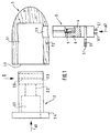
- FIG. 1 to 3 show in a highly schematic representation a spotlight head, by the way, not illustrated lamp with a wooden carved Spotlight housing 1, which is essentially axially symmetrical is constructed and in the front part a cylindrical, has a parabolic shape in the rear.
- the cylindrical interior 1.1 of the spotlight housing 1 has a front insert opening 1.2 and in the lateral lateral surface a push-through opening 1.3.
- an insert part 2 in Arrow direction A1 can be used, the one essentially has cylindrical outer contour and inside an insert cavity 2.1 and a lamp support thread 2.2 has, while at the front end in inserted condition to the front of the spotlight housing 1 applied flange 2.4 is arranged.
- a recess 2.3 with an essentially U-shaped open to the rear Cross-section.
- the arrangement of this recess 2.3 is such that the inserted state of the Insert part 2 is aligned with push-through opening 1.3.
- a push-through part 3 can be used in such a way that it is in the inserted state the insert part 2 through the recess 2.3 is passed through.
- the push-through part 3 serve in the recess 2.3 of the insert part 2 Guide grooves 2.5 of the insert part 2, the corresponding Guide ribs 3.5 on the side walls of the push-through part 3 cooperate.
- other guidance means can also be provided here his.
- a contact carrier 4 is arranged in the push-through part 3, the one central contact 5 and one side contact 6 carries, to which in not specifically shown Way leads 5.1 or 6.1 are connected, which led out of the push-through part 3 on the underside are.
- At the push-through part 3 closes a joint in a manner not shown below over which the lamp head with a support tube or the like is connected and in one piece and materially connected to the push-through part 3 can be.
- the push-through part 3 has a flange 3.1 which when plugged in to the outside of the Spotlight housing 1 creates.
- the flange 3.1 is with provided a through hole 7.1, through which he by means of a screw, not shown, on the spotlight housing 1 can be attached to this Purpose carries a screw hole 7.2.
- the spotlight head shown is installed in such a way that the supply lines 5.1 or 6.1 are connected to the contact carrier 4. Subsequently the contact carrier 4 in the push-through part 3 used.
- FIG. 4 to 7 also show in a highly schematic Representing a spotlight head in a bit another embodiment with a also made of wood worked spotlight housing 11, which is analogous to that Spotlight housing 1 is constructed.
- the cylindrical interior 11.1 of the lamp housing 11 has one front insert opening 11.2 and in the side Shell surface a push-through opening 11.3.
- Insert part 12 can be used in the direction of arrow A1 ' again an interior cavity 12.1 and has a lamp support thread 12.2, while on front end in the inserted state to the Front of the spotlight housing 11 applied Flange 12.4 is arranged.
- This flange 12.4 can, as shown in Fig. 4, part of a Be carrier ring, which is arranged on the insert part 12 External thread 12.7 connected to this is.
- the flange 12.4 ' can also, as in Fig. 5th shown in a variant of this embodiment, integrally connected to the insert part 12 his.
- a push-through part 13 can be used in the inserted state of the insert 12 passed through the insertion opening 12.3 becomes.
- the contact carrier 14 is, as shown in FIGS. 6 and 7 take in a direction A3 ', which is perpendicular to the longitudinal axis and direction of insertion of the push-through part 13 runs, attachable to this such that the cylindrical outer surface 14.1 of the contact carrier 14 in a corresponding cylindrical inner surface 13.2 of the push-through part 13 engages.
- the contact carrier 14 contains a central contact 15 and one Side contact 16, the 14.3 via crimp connections Supply lines 15.1 and 16.1 are connected, which through the push-through part 13 and the joint 18 are led outside.
- the push-through part 13 has a flange 13.1 which when plugged in to the outside of the Spotlight housing 11 creates.
- the flange 13.1 is with provided a through hole 17.1, through which he attached to the spotlight housing 11 by means of a screw can be used for this purpose a screw hole 17.2.
- the spotlight head shown is installed analogously to the example according to FIGS. 1 to 3 in such a way that the leads 15.1 and 16.1 on the contact carrier 14 are connected and the contact carrier 14 to the Push-through part 13 is attached. Then the insert part 12 in the direction of arrow A1 'in the spotlight housing 11 inserted. It is aligned in the end position with the insertion opening 12.3 in the insert part 12 the push-through opening 11.3 in the spotlight housing 11. Then become push-through part 13 and contact carrier 14 in the direction of arrow A2 'in the push-through opening 11.3 the spotlight housing 11 and the insertion opening 12.3 of the insert 12 inserted.
- contact carriers and lamp holder designed such that a Lamp with screw thread, for example with a Lamp base E14 can be used.
- a Lamp with screw thread for example with a Lamp base E14
- contact carrier and Train lamp holder so that, for example, a Halogen low-voltage reflector lamp with lamp pins or a halogen high-voltage lamp with loop contacts can be used.
- the contact carrier in a manner not shown, two plug contacts and the lamp holder a double spring (Flat spring) or it is a double spring educated. This allows lamps with base types GU 5.3 or G 9 in the lamp support device be used.
Landscapes
- Engineering & Computer Science (AREA)
- General Engineering & Computer Science (AREA)
- Fastening Of Light Sources Or Lamp Holders (AREA)
- Non-Portable Lighting Devices Or Systems Thereof (AREA)
- Arrangement Of Elements, Cooling, Sealing, Or The Like Of Lighting Devices (AREA)
Applications Claiming Priority (2)
| Application Number | Priority Date | Filing Date | Title |
|---|---|---|---|
| DE1998122974 DE19822974A1 (de) | 1998-05-25 | 1998-05-25 | Lampenträgereinrichtung an einer Gelenkleuchte mit einem Strahlerkopf |
| DE19822974 | 1998-05-25 |
Publications (2)
| Publication Number | Publication Date |
|---|---|
| EP0961077A2 true EP0961077A2 (fr) | 1999-12-01 |
| EP0961077A3 EP0961077A3 (fr) | 2000-03-08 |
Family
ID=7868636
Family Applications (1)
| Application Number | Title | Priority Date | Filing Date |
|---|---|---|---|
| EP99110037A Withdrawn EP0961077A3 (fr) | 1998-05-25 | 1999-05-21 | Dispositif porte-lampe pour luminaire à bras articulés comprenant une tête d'éclairage |
Country Status (2)
| Country | Link |
|---|---|
| EP (1) | EP0961077A3 (fr) |
| DE (1) | DE19822974A1 (fr) |
Cited By (2)
| Publication number | Priority date | Publication date | Assignee | Title |
|---|---|---|---|---|
| DE10049642C2 (de) * | 2000-10-05 | 2002-12-05 | Vlm W Murjahn Gmbh & Co Kg | Lampenträgereinrichtung für Halogen-Hochvoltlampen mit Zweistiftsockel, insbesondere Sockel GU10 oder GZ10, an einer Strahlerleuchte |
| DE202018105238U1 (de) * | 2018-09-13 | 2019-12-16 | Zumtobel Lighting Gmbh | Leuchte |
Family Cites Families (3)
| Publication number | Priority date | Publication date | Assignee | Title |
|---|---|---|---|---|
| DE9305897U1 (de) * | 1993-04-20 | 1993-06-17 | Brökelmann, Jaeger & Busse GmbH & Co, 5760 Arnsberg | Lampenfassung |
| DE4402089C2 (de) * | 1994-01-25 | 1995-11-16 | Broekelmann Jaeger & Busse | Glühlampenfassung |
| DE4432302C2 (de) * | 1994-09-10 | 1997-01-16 | Murjahn Kg Vlm | In ein Leuchtengehäuse einsetzbare Lampenbefestigungseinrichtung |
-
1998
- 1998-05-25 DE DE1998122974 patent/DE19822974A1/de not_active Ceased
-
1999
- 1999-05-21 EP EP99110037A patent/EP0961077A3/fr not_active Withdrawn
Non-Patent Citations (1)
| Title |
|---|
| None |
Cited By (2)
| Publication number | Priority date | Publication date | Assignee | Title |
|---|---|---|---|---|
| DE10049642C2 (de) * | 2000-10-05 | 2002-12-05 | Vlm W Murjahn Gmbh & Co Kg | Lampenträgereinrichtung für Halogen-Hochvoltlampen mit Zweistiftsockel, insbesondere Sockel GU10 oder GZ10, an einer Strahlerleuchte |
| DE202018105238U1 (de) * | 2018-09-13 | 2019-12-16 | Zumtobel Lighting Gmbh | Leuchte |
Also Published As
| Publication number | Publication date |
|---|---|
| DE19822974A1 (de) | 1999-12-02 |
| EP0961077A3 (fr) | 2000-03-08 |
Similar Documents
| Publication | Publication Date | Title |
|---|---|---|
| EP1851830B1 (fr) | Systeme de liaison, notamment systeme de connexion electrique | |
| EP1264138B1 (fr) | Lampe encastree pourvue d'une bague de retenue pour composants additionnels | |
| DE29917472U1 (de) | Werkzeug mit Beleuchtungsvorrichtung | |
| EP1264136B1 (fr) | Lampe encastree avec reflecteur en forme de dome | |
| DE9214524U1 (de) | Elektrische Lampenfassung aus Kunststoff | |
| EP0961077A2 (fr) | Dispositif porte-lampe pour luminaire à bras articulés comprenant une tête d'éclairage | |
| DE4121575C1 (fr) | ||
| DE8424990U1 (de) | Näherungsschalter | |
| EP0664584A1 (fr) | Douille pour lampe à incandescence | |
| DE586006C (de) | Elektrische Handleuchte | |
| DE19624591C2 (de) | Lampenfassung zur Befestigung in einem Leuchtengehäuse | |
| DE202006009812U1 (de) | Leuchte mit Explosions-Schutz | |
| DE3338628A1 (de) | Einbauscheinwerfer | |
| DE19609547A1 (de) | Leuchte | |
| DE10049642C2 (de) | Lampenträgereinrichtung für Halogen-Hochvoltlampen mit Zweistiftsockel, insbesondere Sockel GU10 oder GZ10, an einer Strahlerleuchte | |
| EP1037324A1 (fr) | Connecteur pour un câble coaxial | |
| DE7705941U1 (de) | Insbesondere wassergeschützte Fassung für Leuchtstofflampen | |
| DE69837191T2 (de) | Leuchte | |
| EP1591715A2 (fr) | Lampe de sécurité avec embout en plusieurs parties | |
| DE3601993A1 (de) | Adapter fuer elektrische gluehlampen | |
| DE29607524U1 (de) | Elektrische Stablampe mit Warnstabfunktion | |
| DE8017078U1 (de) | Leuchte fuer leuchtstoffroehrenlampen mit zweistiftsockeln | |
| DE1962168A1 (de) | Fassung fuer elektrische Gluehlampen | |
| DE1838007U (de) | Fassung fuer elektrische gluehlampen. | |
| EP1013988A2 (fr) | Tête de lampe pour spot |
Legal Events
| Date | Code | Title | Description |
|---|---|---|---|
| PUAI | Public reference made under article 153(3) epc to a published international application that has entered the european phase |
Free format text: ORIGINAL CODE: 0009012 |
|
| AK | Designated contracting states |
Kind code of ref document: A2 Designated state(s): BE DE DK FR IT NL |
|
| AX | Request for extension of the european patent |
Free format text: AL;LT;LV;MK;RO;SI |
|
| PUAL | Search report despatched |
Free format text: ORIGINAL CODE: 0009013 |
|
| AK | Designated contracting states |
Kind code of ref document: A3 Designated state(s): AT BE CH CY DE DK ES FI FR GB GR IE IT LI LU MC NL PT SE |
|
| AX | Request for extension of the european patent |
Free format text: AL;LT;LV;MK;RO;SI |
|
| 17P | Request for examination filed |
Effective date: 20000905 |
|
| AKX | Designation fees paid |
Free format text: BE DE DK FR IT NL |
|
| 17Q | First examination report despatched |
Effective date: 20020607 |
|
| STAA | Information on the status of an ep patent application or granted ep patent |
Free format text: STATUS: THE APPLICATION IS DEEMED TO BE WITHDRAWN |
|
| 18D | Application deemed to be withdrawn |
Effective date: 20021018 |